APIEMS2009 Dec. 14-16, Kitakyushu
Low Cost Head Tracking System for a Desktop-based VR System
Using Webcam
Yap Hwa Jent!, Zahari Taha", Ng Sock Wee3, Chew Jouh Yeong" Centre for Product Design and Manufacturing (CPOM),
Faculty of Engineering, University of Malaya, 50603 Kuala Lumpur, Malaysia.
Email: [email protected]! [email protected] [email protected]
jouhyeongeaperdana.um.edu.my"
Abstract. With the advancement of computer technology, vision-based system has found various applications
ranging from video surveillance, object recognition, industrial defect inspection and autonomous robots. The
fundamental part for many computer vision tasks isobject detection. This paper discusses the development of a
low cost head tracking system for a Desktop-based VR System using a webcam. OpenCv' OpenGL and C/C++
are employed as the development tools for video acquisition, face detection and a virtual environment.
At the jirst stage, a video stream of the webcam is captured. The face is detected by using the Haar-like feature
method. Then, a computer vision technique is used to track the position of the human head in sequence of the
frames of the video stream. The tracking data is jiltered and sent to a VR system in real-time, in which the
position of the objects is moved according to the human head in the video stream of a webcam. Time multiplex
technique is used to create the stereoscopic images and viewed by shutter glasses. Collected data is compared
with video analyzing method and commercial available magnetic sensors. Results obtained demonstrate the
effectiveness of the system in face detection with some limitation such as detecting the face in darkness. The
tracking system is only able to detect 2Dpositions, in which depth cannot be process accurately.
Keywords: OpenCv' OpenGL, Haar-/ike feature, desktop-based VR, real-time
1. INTRODUCTION
Head tracking is of great benefit to users with certain special needs, such as those with amyotrophic lateral sclerosis (ALS), quadriplegia, muscular dystrophy and other conditions (Julie et al. 200 I). Fully able users of gaming and other applications can also benefit from the use of such device as an alternative to the computer mouse (Javier et al.
2009). Head movement can be detected and tracked by computer vision or image processing technique. The digital image can be processed based on relatively simple and fast computations for finding smaller regions of interesting image data.
1.1 Problems Statement
Modern software tracking system is expensive and cumbersome. For example, SmartNAV from Natural Point Inc. use an infrared camera to track a fluorescent circle of
paper placed on the user's forehead (Natural, 2006). Tracer from Boost Technology (Boost, 2006) uses a gyroscope mechanism to sense the movement of the user's head. Both use complex techniques that are only practical in the laboratory. The complexity of the technique slows down the tracking system. The Polhemus Patriot sensor (Polhemus, 2004) suffers interference problems as it is based on an electromagnetic field. Therefore, there is a need for an accurate and fast tracking system which is cheap and practical.
1.2 Objectives
2.
HEAD DETECTION METHODS
The proposed head tracking system employs an image based passive method. It uses face detection algorithms to obtained the head movement. Several methods for face detection are discussed in the following section.
2.1 Template Matching
In this method, the template needs to be predefined. The cross correlation value between the parts (e.g. contour, eyes, nose and mouth) is then computed by searching the small pattern in a image which matches the template. In Henry and Ulises (200 ) research, the template face has to be positioned and rotated in the skin region image to detect the face. For eye detectio , a generic eye model, based on the eye shape, first designed. Template matching is then used to search the image of the eyes (K. Peng et.al, 2005). The model of head translation and head rotation can be used to distinct the sets of templates synthesized from an initially captured image of the head and representing this head in various positions, sizes and orientations for tracking the head (Anne, 1999). This method can detect the eye accurately, but it is insufficient in face detection due to the multi resolution, sub templates, multi scale and deformable templates needed to overcome the variation scale, pose and shape.
2.2 Haar-Like Feature Classification
The Haar-like feature classification object detector is initially propo ed by Paul and Michael (2001) and improved by Rainer and Jochen (2002). Haar-like features are the input to basic classifiers in which a particular classifier is specified by its shape (Figure 1) and position within the region of interest and the scale. Haar-like features have proves to be efficient in image classification because they can be used to encode the existence and spatial relationships in contrast differences between regions in the image (Eoghan, 2006).
!J:.,",,~ Iiiiil
c. ~~-:,
IJJ
CI.1 ~ ~
~<.,~ /
~I ,'0 \ (C) 1.:41 l-e, ~i}
jif
diJCen):ec~~
r.J<p
L::J
(0) t
Figure 1: The set of Haar-like features (Source: Rainer and Jochen 2002)
2.3 Feature Based Methods
Feature based methods focus on comers/straight lines. These methods also can be used to perform segmentation on the basic of intensity or colour (K. Peng et.al, 2005). In
general, these methods have a higher efficiency compared to others. However, these methods are weak with low accuracy for low contrast image. For example. eyebrows may be mistaken for eyes during head detection.
2.4 Skin Detection
Human skin colour is an effective feature in face detection. However. there are three major problems that need to be resolved in order to get the correct information -selection of colour space, modelling of skin colour distribution and colour segmentations processing. Several different colours spaces can be utilized to label pixels as skin including RGB. Vezhnevets et.al (2003) used the pixel-based skin detection methods to classify each pixel as skin or non-skin individually, which is independent from its neighbours
3
SYSTEM ARCHITECTURE
Figure 2 shows the overview of the proposed system. The user's head position is tracked by using a webcam. The video stream is then processed using OpenCv' The tracked data is then sent to a virtual environment to update the stereo images in real-time.
l
t.<
~" '\ t:'$l'.$-\P (E....,.._.·
,~
• V'ioiINAtquiwm.
I'
.
I• I'Oi!li!C1j:.Ge I'
1-/
I
• a.c.e
IleI'a."l_!
-~-
"
r
[....
'\
• l.AAd!D
• T_t:t'.~IJ .~i:!!"C
• ~·limt~
Figure 2: Overview of the System
3.1 Tracking System
The first step in the development of a head tracking system is the face detection algorithm. In this paper, Haar-like feature classification is used for face detection. It consists of a set of features that can be used to encode the contrasts exhibited by a human face and their spatial relationships in the image.
APIEMS2009
• iI.GJI",~ ...
• ?,_w
~*1l:oJ< [image:3.546.11.522.12.820.2]• E.,..~lfi""~d_~::"",,,
Figure 3: Process flow of Tracking System
3.2 Face Centroid Tracking
The Haar Classifier Cascade is then applied again to a region of interest which is of the same size used during the training of an input image. After the face detection image is obtained, further analysis can be implemented. In this paper, the face's centroid is tracked, which is treated as the sensor to control the viewing position in the virtual environment.
(':~~e....~
• fWlitim lk<>:LVT1tk;UY
• 5pK, ... ~~
• Dc6a. .. W.i:di:. St... P-_
~~.~:)
• l(liJiP~_m."'liI.:"lll'Utf_r • r_tl\llf~
• v_""'t ..._
• itul·l:auo ~
• $ltf~..,.,
l't,.~'''''..
Figure 4: System flow of Virtual Environment
Dec. 14-16, Kitakyushu
4
VIRTUAL ENVIRONMENT
The virtual environment is setup as shown in Figure 4. The window is first created and integrated. The callback functions are register to handle events. The viewing volume is then set. Finally, the 3D objects (STL ASCII format) are loaded and drawn.
4.1 Viewing Transformation
Viewing transformation is generally composed of rotations. translations and scales. There are several ways to accomplish viewing transformation such as modelling transformations take object coordinates to world coordinates. viewing transformations take world coordinates to eye coordinates, projection transformation takes eye coordinates to normalized device coordinates (NDCs) and viewport transformation takes NDCs to window coordinates (Andrea,
1999).
Viewing transformation can be grouped as modelling transformations. Itis typically used to set the view the virtual objects in any position. In this paper, glul.ookntt ) in OpenGL is used to creates a viewing matrix that allows the user to look somewhere other than the origin of the scene. There are 9 arguments in this function, which are
glul.ooknt ( eye.\'; eye Y, eyeZ, centerX, centerY, centerZ, upX. up Y, upZ)
The first 3 arguments define the position of the eye point, which is obtained through the tracking system. The next 3 arguments determine the eye focus point, which is the center of the scene. The last 3 arguments define which direction is up.
4.2 Stereo Rendering using OpenGL
Two images are used to generate the stereo rendering, which mimics the traditional stereoscopic camera setup. In computer graphics, viewpoint separation and image shift adjustment can be controlled throughout the image synthesis process. Parallel axis asymmetric frustum perspective projection method is used to produce the stereoscopic images in OpenGL (Paul Bourke, 1999), as shown in Figure 5.
jIIf"tM:l'"
._
Also, the virtual objects are created in positive parallax. This happens in the visual world when looking at objects a great distance from the observer, which will produce images appearing behind the screen. In OpenGL, asymmetric frustum can be created by using:
gIFrustum(left. right. bottom. top. clip_near, clip Jar)
Two new constants dist and eyeSep are introduced in parallel is asymmetric frustum perspective projection. The distance between eyes and screen is dist, and the distance between two eyes is eyeSep . The width and height of the physical screen is dx and dy respectively. and the clipping plane is etween clip_near and clip-far. A similarity factor
(sF =clip_near! dist) is used to obtain the information for
the function. The parameters for the glFrustum of left and right eyes are show in Table l , which only left and right are different or both eyes.
[image:4.546.3.537.105.761.2]Table 1: Parameters forglFrustum
...
IAftEye .... Byeleft - sF • (sWidth - eyeSep)/2 - sF· (sWidth + eyeSep)/2
right
•
sF· (sWidth - eyeSep)/2 sF • (sWidth + eyeSep)/2top sF • sHeightI2 sF • sHeightI2
bottom -top -top
near nearClip nearClip
far I farClip farClip
Also, as shown in Figure 5, viewing vectors for the eyes are parallel. Sach eye is not only viewed from different points, but also different focus points. Therefore. the OpenGL routine gluLookAt( ) is used to create a viewing matrix, with the parameters as shown in Table 2.
Table 2: Parameters forgluLookAt
...
Left
EyeRillfdEye
eyeX - eyeSep /2 eyeSep /2
eveY 0.0 0.0
eyeZ 0.0 0.0
centerX - eyeSep /2 eyeSep /2
centerY - eyeDist - eyeDist
centerZ 0.0 0.0
upX 0.0 0.0
upY 1.0 1.0
upZ 0.0 0.0
4.3 Texture Mapping and Import STL file
Texture mapping is a technique of adding extra information (e.g. surface texture, colour or picture) to the 3D model or computer generated graphic. It can be applied to a surface or polygon. This process is akin to applying patterned paper to a plain white box (Dave et.al, 1997).
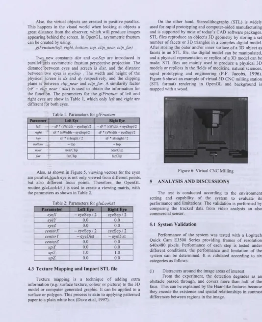
On the other hand. Stereolithography (STL) is widely used for rapid prototyping and computer-aided manufacturing and is supported by most of today' s CAD software packages. STL files reproduce an object's 3D geometry by storing a set number of facets or 3D triangles in a complex digital model. After storing the outer and/or inner surface of a 3D object as facets in an STL file, the digital model can be manipulated, and a physical representation or replica of a 3D model can be made. STL files are mainly used to produce a physical 3D models or replicas in the fields of medicine, natural sciences, rapid prototyping and engineering (P.F. Jacobs, 1996). Figure 6 shows an example of virtual 3D CNC milling station (STL format) rendering in OpenGL and background is mapped with a wood.
Figure 6: Virtual CNC Milling
5 ANALYSIS AND DISCUSSIONS
The test is conducted according to the environment setting and capability of the system to evaluate its performance and limitations. The validation is performed by comparing the tracked data from video analysis an also commercial sensor.
5.1 System Validation
Performance of the system was tested with a Logitech Quick Cam E3500 Series providing frames of resolution 640x480 pixels. Performance of each step is tested under different conditions. the performance and limitation of the system can be determined. It is validated according to six categories as follows:
(i) Distracters around the image areas of interest
APIEMS2009
(ii) Variable lightening
The system can track the face accurately in bright environment and circumstances. However, in darkness. the tracking becomes unstable that is it would detect the human neck as the face. This is because in the dark, the neck is almost become darkness with some brightness, it is same contrast colors with the eyes and nose with the eyes are darker and nose is more brightness.
(iii) Different size of face image
The system is able to track the different size of the image such as the smallest image far from camera to the largest image close to the camera, or a user with different size of faces.
(iv) Wearing spectacles
This test is very important because the user need to wear the liquid shutter glasses to view the stereoscopic image. From the experiment, the developed system can detect and track the face successfully while wearing the glasses.
(v) Multiple faces detection
The system has the ability to detect multiple faces. This is important when the system is required to track multiple faces in a window. However, only the first person's head position will be used in virtual environment. The faces will defined by the different colors. e.g red for first person and blue for second person.
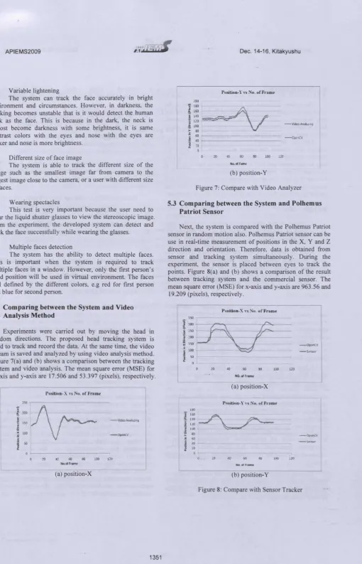
5.2 Comparing between the System and Video , Analysis Method
Experiments were carried out by moving the head in random directions. The proposed head tracking system is used to track and record the data. At the same time, the video stream is saved and analyzed by using video analysis method. Figure 7(a) and (b) shows a comparison between the tracking system and video analysis. The mean square error (MSE) for x-axis and y-axis are 17.506 and 53.397 (pixels), respectively.
Pesition-X vs No. ofFrom.
250 ..
-OpenCV
50!
o .;.----.-- ---- ,.. - -..-.¥ -- --~---.-- ---- --,
o m m 00 ~ ~ ill
~.ofFfame
(a) position-X
Dec. 14-16, Kitakyushu
Position- Y\'5No.of Frame
,"0
::~.~
120
100
30
oo~---40 .,... 20
20 40 W 80 100 no
No. of Fame
[image:5.546.28.538.23.816.2](b) position- Y
Figure 7: Compare with Video Analyzer
5.3 Comparing between the System and Polhemus Patriot Sensor
Next, the system is compared with the Polhemus Patriot sensor in random motion also. Polhemus Patriot sensor can be use in real-time measurement of positions in the X, Y and Z direction and orientation. Therefore, data is obtained from sensor and tracking system simultaneously. During the experiment, the sensor is placed between eyes to track the points. Figure 8(a) and (b) shows a comparison of the result between tracking system and the commercial sensor. The mean square error (MSE) for x-axis and y-axis are 963.56 and
19.209 (pixels), respectively.
Position-X vsNo.of'Frnme
-O"et'lCV
-S<!,(lsor
10
o .;...
o 20 40 60 80 100 1.l0
NO.ofFrome
(a) position-X
Posttton-Yvs No.of Frame
180
t60~
~:
. . - .. ..'100 .
-SoH1SOt"
20 '0 GO 80 100 120
No.of Frame
(b) position- Y
6 CONCLUSIONS
The system is simple and inexpensive compared to the other complex and expensive system in the market. The low cost webcam is used without any camera lens adjustment. Most notebooks nowadays come with built-in webcam, which can be used to create interactive virtual games.
Alth rugh the webcam is cheap, but it is sufficient to capture . nd process the image effectively. The Haar-like features method is used in the proposed system and it is fast, easy to implement and able to detect/analysis video stream in real-time. There was less computation for this method because ir is uses the set of features in tracking, which will reduce th latency and delay. It can be treated as a low cost sensor by tracking the position of the object in XIY direction.
,
REFERENCES
Andrea Fusiello (1999), Viewing,
http://profs.sci.univr.it/-colombar/html_ openGL _tutorial/en!
08viewing_003.html. Access date: 15 March 2009 .
•
Anne Lavergne (1999), Computer Vision System for
Head Movement Detection and Tracking, Master Thesis,
University fBritish Columbia.
Boost Technology (2006), Tracer,
http://www.boosttechnology.com/testchart. html. Access date: 30 March 2009.
Dave Shreiner, Mason Woo, Jackie Neider, Tom Davis and OpenGi Architecture Review Board (1997), OpenGL
Programming Guide: The Official Guide to Learning
OpenGL, 6thedition, Addison-Wesley.
Eoghan McCabe (2006), A Software Face Tracker Using
a Webcam, Final Year Project, B.A. (Mod.) Computer
Science, The University of Dublin.
Henry Chang and Ulises Robles (2000) Face Detection,
http://www-csstudents.stanford.edu/-robles/ee368/
matching.html. Access date: 15 March 2009.
Javier San Agustin, Julio C. Mateo, John Paulin Hansen and Arantxa (2009) Evaluation of the Potential of Gaze Input for Game Interaction, PsychNology Journal, ISSN 1720-2525, Vol. 7 No.2, 213 _ 236.
Julie A. Jacko and Holly S. Vitense (2001) A Review and Reappraisal of Information Technologies within a Conceptual Framework for Individuals with Disabilities,
Universal Access in the Information Society, ISSN 1615-5289,
1,56-76.
K. Peng, Liming Chen. Su Ruan, and Georgy Kukharev (2005), A Robust Algorithm for Eye Detection on Gray Intensity Face without Spectacles, Journal of Computer Science &Technology. Vol. 5 No.3. 127-132.
Natural Point Inc. (2006), Smart-Nav,
http://www.naturalpoint.com/smartnav/ Access date: 30 March 2009.
P.F. Jacobs (1996) Stereolithography and Other RP&M Technologies, Society of Manufacturing Engineers.
Paul Bourke (1999) Calculating Stereo Pairs http://local.wasp .uwa. ed u.au/s-pbourke/mi scellaneous/stereog raphics/stereorender/. Access date: 15 March 2009.
Paul Viola and Michael J. Jones (200 I). Rapid Object Detection using a Boosted Cascade of Simple Features, IEEE
Computer Society Conference on Computer Vision and
Pattern Recognition. Vol. I.IEEE, 1-9.
Polhemus (2004), Polhemus Patriot Sensor, Available at:
http://wwwpolhemus.com/?page=Motion _Patriot. Access date: 30 March 2009.
Rainer Lienhart and Jochen Maydt (2002), An Extended Set of Haar-like Features for Rapid Object Detection, IEEE
International Conference on Image Processing, Vol. I,
900-903.
Vezhnevets V, Sazonov V,. Andreeva A. (2003) A Survey on Pixel-based Skin Color Detection Techniques.
Proceedings of Graphic on, 85-92.
AUTHOR BIOGRAPHIES
Yap Hwa Jen is a researcher cum PhD student in the Centre of Product Design and Manufacture (CPDM), University of Malaya, Malaysia. He is also a Lecturer in the Department of Engineering Design and Manufacture, Faculty of Engineering, University of Malaya, Malaysia. He obtained his bachelor degree in Mechanical Engineering with Honors from the University of Malaya in 2000 and Master of Engineering Science from University of Malaya in 2005. His research interests included virtual reality, human-computer interface, product design, robotics and automation. His email address is <[email protected]>