International Journal of Emerging Technology and Advanced Engineering
Website: www.ijetae.com (ISSN 2250-2459,ISO 9001:2008 Certified Journal, Volume 3, Issue 10, October 2013)
395
Modeling and Simulation of IM Drive Performance Using PI,
ANN and FLC
D. Nikhitha
1, J. N. Chandra Sekhar
21
M.Tech student, 2Assistant professor, Department of EEE, SVU College of Engineering, Tirupati, Andhra Pradesh, India.
Abstract--In this paper an implementation of unified intelligent controller methods for voltage controlled PWM driven three phase Induction Motor drive system has been developed and analyzed in detail. The Induction motor drive system involve dynamic d-q model in synchronously rotating frame. The performance of proportional controller
(PI), Fuzzy and Artificial Neural Networks (ANN) has been
investigated through MATLAB/Simulink environment. Finally the results are compared and validate that ANN is predictable, greater and give better responses than Fuzzy and PI controllers.
Keywords-- Induction motor, dynamic modelling, Fuzzy
logic controller, Artificial Neural networks,
MATLAB/SIMULINK.
I. INTRODUCTION
The induction motors are the most widely used electric motors in industry. It‘s, known for its robustness, relatively low cost, reliability and efficiency, is the object of several research works. However its control presents difficulties because of its high non-linearity and its highly coupled structure [1]. Induction motors are the most widely used motors for appliances like industrial control, and automation; hence, they are often called the workhorse of the motion industry. The AC induction motor is well suited to applications requiring constant speed operation. In general, the induction motor is cheaper and easier to maintain compared to other alternatives. Nowadays, as a consequence of the important progress in power electronics and micro-computing, the control of AC electric machines has seen considerable development and the possibility for application. Starting from this basis, the DTC scheme [2] is characterized by the absence of PI regulators coordinate transformations current regulators PWM signals generators (no timers)[3]. The direct torque control scheme was later introduced to control the torque and flux directly based on the instantaneous errors in the torque and flux. It does eliminate the encoder required to measure rotor speed and has significantly higher dynamic performance due to the lack of the PI controller. The hysteresis based switching of the inverter results in high torque ripple and current distortion. Induction motor torque control has traditionally been achieved using FOC.
This is a relatively simple but effective control scheme. Its disadvantages are that it requires an encoder to measure rotor speed, it is sensitive to parameter detuning and the PI controller that regulates the stator current limits the transient response [4].
II. INDUCTION MOTOR MODEL
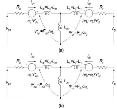
[image:1.595.329.528.338.522.2]The induction machine d-q or dynamic equivalent circuit is shown in Fig. 1.
Fig 1: Dynamic or d-q equivalent circuit of an induction Machine
Where d: direct axis, q: quadrature axis, s: stator variable, r: rotor variable,
Vqs, Vds: q & d axis stator voltages,
Vqr, Vqr: q & d axis rotor voltages,
Fmq , Fmd: q & d axis magnetizing flux linkages
Rr : rotor resistance,
Rs: stator resistance,
Xls: stator leakage reactance (we Lls),
Xlr: rotor leakage reactance (we Llr).
III. SIMULINK IMPLEMENTATION
Driving the model equations can be generated from the dq0 equivalent circuit of the induction machine shown in
International Journal of Emerging Technology and Advanced Engineering
Website: www.ijetae.com (ISSN 2250-2459,ISO 9001:2008 Certified Journal, Volume 3, Issue 10, October 2013)
396
=ωb[Vqs- +
(ψmq-ψqs)]...(1)
=ωb[Vqs+ +
(ψmd-ψds)]...(2)
=ωb[Vqr
+
(ψmq-ψqr)]...(3)
=ωb[Vdr
+
(ψmd-ψdr)]...(4)
Where
Ψmq=Xml [
+
]...(5)
Ψmd=Xml [
+
]...(6)
Xml=1/(
)...(7)
Then substituting the values of the flux linkages to find the currents:
Iqs=
(ψqs-ψmq)...(8)
Ids=
(ψds-ψmd)...(9)
Iqr=
(ψqr-ψmq)...(10)
Idr=
(ψdr-ψmd)...(11)
Based on the above equations, the torque and rotor speed can be determined as follows:
Te= ( ) ( )...(12)
ωr=∫ (Te-TL)...(13)
Where P: number of poles; J: moment of inertia (Kg/m2). For squirrel cage induction motor, the rotor voltages Vqrand Vdrin the flux equations are set to zero since the rotor cage bars are shorted. After driving the torque and speed equations in term of d-q flux linkages and currents of the stator, the d-q axis transformation should now be applied to the machine input (stator) voltages.
The three-phase stator voltages of an induction machine under balanced conditions can be expressed as:
Va=√ Vrms sin (ωt)...(14)
Vb=√ Vrms sin
)...(15)
Vc=√ Vrms sin
)...(16)
These three-phase voltages are transferred to a synchronously rotating reference frame in only two phases (d-q axis transformation). This can be done using the following two equations.
[ ]=* + [
√ √ ] [ ]...(17)
Then, the direct and quadrature axes voltages are
[ ]=*
+ [ ]...(18)
The instantaneous values of the stator and rotor currents in three-phase system are ultimately calculated using the following transformation:
[ ]=*
+ [ ]...(19)
[ ] [ √ √
] [ ]...(20)
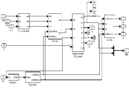
The inputs of a squirrel cage induction machine are the three phase voltages, their fundamental frequency, and the load torque. The outputs, on the other hand, are the three phase currents, the electrical torque, and the rotor speed. The d-q model requires that all the three-phase variables be transformed to the two–phase synchronously rotating frame Consequently, the induction machine model will have blocks transforming the three-phase voltages to the d-q frame and the d-q currents back to three-phase The induction machine model implemented in this paper is shown in Fig.( 2). It consists of five major blocks: the o-n conversion, abc-syn conversion, syn-abc conversion, unit vector calculation, and induction machine d-q model blocks.
Fig (2): Induction motor dynamic model
IV. GENERALIZED MODEL &ANALYSIS BY VARIOUS
CONTROLLEERS
(A) PI Controller
[image:2.595.318.545.441.597.2]International Journal of Emerging Technology and Advanced Engineering
Website: www.ijetae.com (ISSN 2250-2459,ISO 9001:2008 Certified Journal, Volume 3, Issue 10, October 2013)
397
However in this paper PI controller is considered, in which the controller parameters are adapted to the controller structure, and structurally optimized controllers, in which the controller structure and parameters are adapted optimally to the structure and parameters of the process model.The proportional controller is a device that produces an output signal which is proportional to the input signal. It improves the steady state tracking accuracy, disturbance signal rejection and relative stability. It also decreases the sensitivity of the system to parameter variations. The PI controller produces an output signal consisting of two terms- one proportional to input signal and the other proportional to the integral of input signal. The concerns of PI controller in the system are to reduce the steady state error and increased the order and type of the system by one which is shown in Fig.3.
Fig.(3) Block Diagram of PI controller
Transfer function (PI) = Kp +Ki /S
The output signal of the controller will be sent to the Vector rotator, and finally control the Induction motor drive is shown in Fig(4). So, the use of the PI controller is ubiquitous in industry. It has been stated, for example, that in process control applications, and more than 95% of the controller is PI type.
Fig(4):PI controller
(B)Fuzzy Controller
The implementation of offline tuning of PI controller is difficult in dealing with continuous Parametric variation in the induction motor as well as the nonlinearity present in the entire system. However, the fuzzy logic bases intelligent controller is used instead of the PI controller, excellent control performance can be achieved even in the presence of parameter variation and drive nonlinearity.
The work presented in uses a Fuzzy Logic Controller to set the torque component of reference current based on speed error and change of speed error. The inverter is then switched to follow the reference current within hysteresis band. However, the constant hysteresis band of the current regulated Voltage Source Inverter of the Fuzzy logic control system possesses problem in achieving superior dynamic performance, even the drive control system includes the efficient Fuzzy logic controller. This paper discusses the fuzzy logic speed control for induction motor drives. Fig. 6 shows the block diagram of Fuzzy logic based speed control system. Such a Fuzzy logic controller consists of four basic blocks viz., Fuzzification, Fuzzy Inference Engine, Knowledge base and defuzzification
i. Fuzzification And Fuzzy Interference
In this stage, the crisp variables error signal E and change in error signal dE (k) are converted in to fuzzy variables and respectively. The membership functions associated to the control variables [9] have been chosen with triangular shapes as shown in Fig. (5). The universe of discourse of all the input and output variables are established as (-1, 1). The suitable scaling factors are chosen to bring the input variables to this universe of discourse.
The universe of discourse is divided into seven overlapping fuzzy sets: NL (Negative Large), NM (Negative Medium), NS (Negative Small), ZE (Zero), PS (Positive Small), PM (positive Medium), and PL (Positive Large) and the output variables to this universe of discourse is divided into nine overlapping fuzzy sets with an addition of NVL (Negative Very Large) and PVL (Positive Very Large) to the input variables. Each fuzzy variable is a member of the subsets with a degree of membership varying between 0 (non member) and 1 (full member).
(a) Speed error (b) Change of Speed error
(c) Change of Command current
International Journal of Emerging Technology and Advanced Engineering
Website: www.ijetae.com (ISSN 2250-2459,ISO 9001:2008 Certified Journal, Volume 3, Issue 10, October 2013)
398
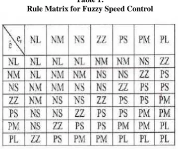
ii. Knowledge Base And Inference Stage [image:4.595.319.542.141.322.2]Knowledge base involves defining the rules represented as IF-THEN statements governing the relationship between input and output variables in terms of membership functions. In this stage, the variables E and dE are processed by an inference engine that executes 49 rules which is shown in Table.1. These rules are established using the knowledge of the system behaviour and the experience of the control engineers.
Table 1:
Rule Matrix for Fuzzy Speed Control
In this stage a crisp value of the output variable dF(k) is obtained by using height defuzzufication method, in which the centroid of each output membership function for each rule is first evaluated. The final output is then calculated as the average of the individual centroid, weighted by their heights (degree of membership) as follows:
Where n is the number of quantization levels of the output.
The inputs to the fuzzy logic controller are the speed error and rate of change of speed error. The output is fed to the power converter-pwm inverter, which is used to adjust the inverter switching control frequency. The output of FLC controls the firing angle of the inverter, thereby varying the output voltages. The reference speed of the pwm inverter is modified each time when there is a different output of the fuzzy controller. These outputs are found from the truth table (rule table). The pwm inverter output is then fed to the induction machine where a constant V/Hz operation is carried out. The Voltage/Hertz Control induction motor using fuzzy logic controller, which has been implemented in Fig (6).
Fig(6):Implementation of induction motor using fuzzy logic controller.
(C) Neural-Networks
Neural-networks are one of those words that are getting fashionable in the new era of technology. The term 'neural network' is in fact a biological term, and what we refer to as neural networks should really be called Artificial Neural Networks (ANNs). The ANN has been successfully applied to identify and control the currents of an induction machine. By using neural controller the peak overshoot is reduced and the system reaches the steady state quickly when compared to a conventional PI controller [10].
[image:4.595.73.253.253.403.2]International Journal of Emerging Technology and Advanced Engineering
Website: www.ijetae.com (ISSN 2250-2459,ISO 9001:2008 Certified Journal, Volume 3, Issue 10, October 2013)
399
Neural Network Application DevelopmentThe Flowchart for BPA is shown in shown below:
Flowchart:
Algorithm:
The Algorithm for the flowchart shown below: (Step 0) Initialization:
Randomly assign the weights to all Layers: (Method 1) Weights selected from [-1, 1] (Method 2) Ng-Widrow Procedure
Set the iteration number p=1 and go to Step(1).
(Step 1) Select one of the training samples
Method 1- Fixed order: Define order that the training samples are to be drawn and keep order through successive samples and all passes through data.
Method 2- Multiple Fixed orders: Use different specific ordering through different passes through data.
Method 3- Fully Random Order . Randomly select order through each pass through the data.
Using one of the methods above select a training sample x(p) which includes the pattern vector and the class assignment. Then go to Step (2).
(Step 2) Calculate outputs of each layer:
Using selected sample x(p) and weights matrices for each layer W(k)(p), k=1 to NL
calculate outputs y(1)(p) of all nodes in layer 1, and then calculate all outputs in successive layers y(k)(p), k = 2, 3, …, NL. Store all nodal outputs in memory.
Then Go To step(3)
(Step 3) Calculation of performance: Single Sample Error:
Over all Samples Error:
When error gets small this approximation becomes pretty good! This approximation can be computed recursively taking care to avoid round off errors by
ETOTAL(p+1) = ETOTAL(p) + Ep+1 (p+1) – Ep-Ns (p-Ns )
Then go to step (4) .
(Step 4) Branch on Error Tolerance: If performance not satisfied,
ETOTAL(p) > ε (acceptable total error)
then go to step(5) .
If performance is satisfied then the current weights and structure provide the required design and the algorithm is stopped.
(Step 5) Branch on Maximum number of Iterations :
If p=NMAX then algorithm stops and NO acceptable
design is obtained.
If p < NMAX
then go to step(6) (algorithm continues).
(Step 6) Calculation of weight changes using weight update equations:
Calculate the weight changes and new weights for the last (L)th layer using the outputs from step (3) and the current input sample x(p) using Rule #1 for each nonlinearity. Continue calculating new weights in reverse order for preceding L-1 Layers to the first layer using Rule #2 and modified Rule #2.
If training by epoch, the weight changes will be accumulated for each sample though one entire pass through the data before changing weights and then go to step (7) .
(Step 7) update the weight matrices:
Update all weight matrices for all layers to get new weight matrices W(k)(p+1) and then go to step (1).
International Journal of Emerging Technology and Advanced Engineering
Website: www.ijetae.com (ISSN 2250-2459,ISO 9001:2008 Certified Journal, Volume 3, Issue 10, October 2013)
400
Fig(7):implementation of induction motor using ANNV. SIMULATION RESULTS
To test the model, the induction machine is simulated by applying 220 V three-phase ac voltages at 60 Hz with just an inertia load. To analyze the performance of induction motor using PI, Fuzzy Logic and NN are simulated. In all cases, the dynamic responses of speed and stator currents for the starting process with torque applied and a constant command flux are shown in simulation results. The simulation results of three controllers with respect to time are presented below:
Time(sec)
Time(sec)
Time(sec)
Fig(8a):PI controller
Time(sec)
Time(sec)
Time(sec)
Fig(8b):Fuzzy controller
Time(sec)
Time(sec)
S
p
ee
d
(r
ad
/s
ec
)
S
p
ee
d
(r
ad
/s
ec
)
To
rq
u
e(
N
-m)
C
u
rr
en
t(
amp
)
S
p
ee
d
(r
ad
/s
ec
)
To
rq
u
e(
N
-m)
C
u
rr
en
t(
amp
)
To
rq
u
e(
N
International Journal of Emerging Technology and Advanced Engineering
Website: www.ijetae.com (ISSN 2250-2459,ISO 9001:2008 Certified Journal, Volume 3, Issue 10, October 2013)
401
Time(sec)
Fig(9c):ANN controller
VI. CONCLUSION
The conventional PI controller was designed for a laboratory level process station. Then the PI controller was replaced by Fuzzy controller. Similarly Neuro controller was also implemented for the same set up. The performance of all the three controllers was validated. High performance control schemes of an induction motor invariably rely on the knowledge of at least some of the motor parameters. It is evident from table 1 that the values for the neuro-controller was slightly better than the fuzzy controller. To conclude with, both the intelligent controllers perform well when compared to conventional PI controller. The introduction of the ANN controller led to an improvement in the speed regulation of the IM, which leads us to say that optimization by ANN controller gives us the possibility of designing a powerful Induction motor drive system. The accurate response is possible using ANN controller.
Future Scope:
As a future work, a better control scheme can be implemented with expert systems such as combination of fuzzy and neural network and GA for obtaining optimum efficiency at all loading conditions.
REFERENCES
[1] A. Mansouri, M. Chenafa, A. Bouhenna, E. Etien ‗Power Nonlinear Observer Associated with Field-oriented Control of an Induction Motor‘. Int. J. Appl. Math. Comput. Sci., 2004, Vol. 14, No. 2, 209-220
[2] D.Casadei,F. Profumo, G.Serra and A. Tani, FOC and DTC: Tox viable schemes for induction motors Torque control, IEEE Trans. Power Electronics, vol. 17, n° 5, Sept 2002.
[3] Y miloud and A.Draou.‖ Application of a Three Level GTO Voltage Source PWM Inverter to feed AC Motors for Variable-Speed Drive with a PI- Controller‖. International Conference on Electronics, ICEL‘ 2000. Vol. 1, November 13-15. pp 223-227. Oran, Algeria.
[4] J.Holtz, E.Bube, Field Oriented asynchronous PWM for high performance AC machine drives operating at low switching frequency, IEEE Transactions on Industrial Applications, vol.27: .574-581, 1991.
[5] S. Kirkpatrick, C. D. Gelatt, and M. P. Vecchi, ―Optimization by simulated annealing,‖ Science, vol. 220, pp. 671–680, 1983. [6] A. Colorni, M. Dorigo, and V. Maniezzo, ―Distributed
optimization by ant colonies.‖ in Proceedings of ECAL91 - European Conference on Artificial Life,. Elsevier Publishing, 1991.
[7] J. Kennedy and R. C. Eberhart, ―Particle swarm optimization,‖ in Proc. of the IEEE Int. Conf. on Neural Networks. Piscataway, NJ: IEEE Service Center, 1995, pp. 1942–1948.
[8] Rejani K. Mudi and Nikhil R. Pal, ― A Robust Self-Tuning Scheme for PI-and PD-Type Fuzzy Controllers‖. IEEE Trans. Fuzzy Systems, Vol.7, February 1999, pp 2-14.
[9] Vinod Kumar, R. R. Joshi, ―Hybrid Controller based Intelligent Speed Control of Induction Motor‖, Journal of Theoretical and Applied Information Technology, December 2006, Vol. 3 No. 1, pp. 71 75.
[10] Howard Demuth, Mark Beal, ―Neural Network Toolbox for Use with Matlab‖, User Guide, the Math Work Inc. June 1992 [11] Kung Y.S., Liaw C.M. and Ouyang M.S. (2005): Adaptive speed
control for induction motor drives using neural networks.—IEEE Trans. Industry. Electr., Vol. 42, No. 1, pp. 25–32.
C
u
rr
en
t(
amp