International Journal of Emerging Technology and Advanced Engineering
Website: www.ijetae.com (ISSN 2250-2459, ISO 9001:2008 Certified Journal, Volume 6, Issue 7, July 2016)
137
Design and Implementation of low power Ring VCO Using Tail
Transistor
Prachi S. Athare
1, S. P. Agnihotri
2, Y. A. Salame
31Student, 2Head, 3Assistant Professor, Dept. of Electronics & Telecommunication, Gokhale Education Society’s R. H. Sapat
College of Engineering, Management Studies and Research, Nashik, Maharashtra, India
Abstract— A CMOS voltage controlled ring oscillator based on 3 stages of inverter is described in this paper. This paper gives the comparison different parameters like phase noise, power consumption and figure of merit of LC VCO Using Memory Reduction Tail Transistor Topology and Ring VCO using Without Tail Transistor Topology, Fixed Biased Tail Transistor Topology and Memory Reduction Tail Transistor Topology. The presented results are obtained using microwind3.1 software in 18nm technology.
Keywords— CMOS, Voltage Control Oscillator (VCO) , Phase Noise, Power, Figure of Merit.
I. INTRODUCTION
Now a day, VCOs are widely used in wireless optical communication especially in PLL, timing recovery and frequency synthesizer system. VCO is one of the key component in phase locked loop. Several techniques are available to improve phase noise performance. Numerous electronic systems having different kinds of oscillator which are operate for generating the signal. The VCO is an electronic oscillator whose oscillation frequency is controlled by input voltage .This paper contains LC voltage control oscillator and Ring voltage control oscillator using tail transistor which is designed using Microwind3.1 software in 18nm technology. The main challenge in the design of LC VCO and Ring VCO is to calculate low phase noise while maintaining low power consumption and figure of merit. The inductor and capacitor is having poor quality factor and it directly affects the phase noise performance. Hence phase noise performance is enhance by improving the quality factor.
Integrated LC voltage control oscillator are critical building blocks in high performance communication systems. The LC Voltage Control Oscillator plays most important role in RF transreceivers.
There are two main types of Ring Voltage Control Oscillator such as Single ended and differential Ring Voltage Control Oscillators. The delay cell for single ended Voltage Control Oscillator is a basic inverter and it has the highest frequency of oscillations and low power consumption. The phase noise, frequency are the important characteristics of Ring Voltage Control Oscillator.
CMOS Voltage Control Oscillator is implemented by using 90nm technology with ring coupled quad[1]. An ideal Ring Oscillator topology for multiphase output is being implemented and analyzed[3]. The relationship that power consumption of the VCO depends on transistor sizes rather than operating frequencies[4].Evaluation of the oscillation frequency of a ring oscillator is being carried out[5]. A phase lock loop is being developed by using Voltage Control Oscillator[9].Oscillation frequency of a ring oscillator has been calculated by using new equation[11].Analysis of single ended and differential ended Ring Oscillator is presented[12].
II. IMPORTANT PARAMETERS
1) Phase Noise
Phase Noise is an important parameter which is used to determine frequency stability of the periodic signal. Phase noise is nothing but the ratio of signal power to the noise power. Phase noise is directly affects on the performance of the system.. The main feature of an oscillator is to produce similar frequency over a described period of time. Phase Noise can be calculated by
(1) Where,
SSSB=Phase Noise of an oscillator F= Noise Factor
K= Boltzman Constant (1.38⨯10-23) PS= Average Signal Power
T= Temperature
But Signal Power Can be calculated as,
International Journal of Emerging Technology and Advanced Engineering
Website: www.ijetae.com (ISSN 2250-2459, ISO 9001:2008 Certified Journal, Volume 6, Issue 7, July 2016)
[image:2.612.367.516.185.290.2]138 2) Figure Of Merit
Figure of merit is the number or value which is used for distinguishing the performance of the various systems. It directly depends on the quality factor Figure of merit is always expressed in dB and it can be calculated as,
(3) Where,
PC= Calculated Power
III. PROPOSED SYSTEM
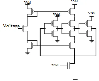
[image:2.612.48.276.288.461.2]A. LC Voltage Control Oscillator Using Memory Reduction Tail Transistor Topology:
Fig-1: LC VCO Using Memory Reduction Tail Transistor Topology
The given system is depends on the NMOS transistor tail current source. The fig. 1 shows the LC VCO architecture of tail transistor using Memory Reduction technique. The tail transistor is always work in a saturation region when it starts its oscillations. These transistors are always switched biasing instead of fixed biasing. Therefore it reduces the flicker noise.
B. Ring Voltage Control Oscillator Using Tail Transistor Topology
1) Ring VCO Using Without Tail Transistor Topology
Ring VCO using Without Tail Transistor Topology is shown in Fig. 2 Ring VCO circuit is mainly built from PMOS and NMOS transistors. Frequency of oscillation for Ring Voltage Control Oscillator is calculated by,
(4)
Equation (4) states that frequency is depends on the number of stages that means if number of stages increases the frequency of oscillation will become decreases.
Fig- 2: Ring VCO Using Without Tail Transistor Topology
2) Ring VCO Using Fixed Biased Tail Transistor Topology
Ring Voltage Control Oscillator using Fixed Biased Tail Transistor Topology is as shown in the Fig. 3. It gives good power consumption and phase noise as compared to the Ring Voltage Control Oscillator using Without Tail Transistor Topology.
Fig-3: Ring VCO using Fixed Biased Tail Transistor Topology
3) Ring VCO Using Memory Reduction Tail Transistor Topology
[image:2.612.358.531.412.554.2]International Journal of Emerging Technology and Advanced Engineering
Website: www.ijetae.com (ISSN 2250-2459, ISO 9001:2008 Certified Journal, Volume 6, Issue 7, July 2016)
139
Fig- 4: Ring VCO using Memory Reduction Tail Transistor Topology
IV. PERFORMANCE COMPARISON OF DIFFERENT
PARAMETERS OF LC VCO AND RING VCO
For LC Voltage Control Oscillator using Memory Reduction Tail Transistor Topology, it gets -123 dBc/Hz while maintaining low power consumption which is 3.078mW and Figure of merit is 186.
For Ring Voltage Control Oscillator, it gives better phase noise performance, low power consumption and figure of merit as compared to LC Voltage Control Oscillator. For Fixed Biased Tail Transistor Topology, it gives better phase noise performance, low power consumption and figure of merit over Without Tail Transistor Topology.
V. LAYOUT AND SIMULATION RESULT
[image:3.612.326.563.112.361.2]A. Ring VCO using Tail Transistor Topologies 1) Without Tail Transistor Topology
[image:3.612.106.269.141.281.2]Fig- 5 Layout of Ring VCO using Without Tail Transistor Topology
Fig- 6: Output of Ring VCO using Without Tail Transistor Topology
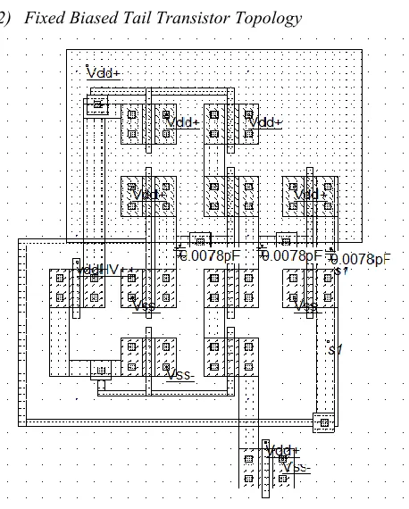
2) Fixed Biased Tail Transistor Topology
[image:3.612.326.555.377.662.2] [image:3.612.47.289.477.692.2]International Journal of Emerging Technology and Advanced Engineering
Website: www.ijetae.com (ISSN 2250-2459, ISO 9001:2008 Certified Journal, Volume 6, Issue 7, July 2016)
140
Fig-8: Output of Ring VCO using Fixed Biased Tail Transistor Topology
3) Memory Reduction Tail Transistor Topology
Fig- 9: Layout of Ring VCO using Memory Reduction Tail Transistor Topology
Fig- 10: Output of Ring VCO using Memory Reduction Tail Transistor Topology
TABLEI
FOR 18NM TECHNOLOGY @1.88GHZ
Parameters LC VCO Ring VCO
MR WT FB MR
Phase Noise -123 -179 -187 -190
Power(mW) 3.078 0.453 0.442 0.44
FOM 186 224 231 234
VI. CONCLUSION
The VCOs are generally used in function generators, production of electronic music, phase lock loop, frequency synthesizers etc. The RF CMOS LC VCO and Ring VCO using Tail Transistor Topology has been designed and simulated by using Microwind3.1 software in 18nm technology. This paper gives the comparison of LC VCO and Ring VCO in terms of parameters such as phase noise, power consumption and figure of merit. Ring VCO using tail transistor gives better phase noise performance and power consumption as compared to LC VCO using tail transistor. The novel topology gives -190dBc/Hz phase noise at 1.88GHz.
REFERENCES
[1] Zuo-Min Tsai, Chin-Shen Lin, C. F. Huang, John G. J. Chern, and Huei Wang, “A Fundamental 90-GHz CMOS VCO Using New Ring-Coupled Quad”, IEEE MICROWAVE AND WIRELESS COMPONENTS LETTERS, VOL. 17, NO. 3, MARCH 2007 [2] C. H. PARK, O. KIM, B. KIM, “A 1.8-GHz self-calibrated phase
locked loop with precise I/Q matching”, IEEE J. Solid-State Circuits, vol. 36, (2001), 777-783.
[3] L. SUN AND T. A. KWASNIEWSKI, “A 1.25-GHz 0.35- m monolithic CMOS PLL based on a multiphase ring oscillator”, IEEE J. Solid-State Circuits, vol. 36, (2001), 910-916.
[4] Oscal T.-C. Chen and Robin Ruey-Bin Sheen, “A Power-Efficient Wide-Range Phase Locked Loop”, IEEE JOURNAL OF SOLID-STATE CIRCUITS , VOL. 37, NO. 1,JANUARY 2002
[5] C. K. K. YANG, R. FARJAD-RAD, M. A. HOROWITZ, “A 0.5- m CMOS 4.0-Gbit/s serial link transceiver with data recovery using oversampling”, IEEEJ.Solid-StateCircuits,vol.33, (1998), 713-722. [6] M. ALIOTO, G. PALUMBO, “Oscillation frequency in CML and
ESCL ring oscillators”, IEEE Trans. Circuits Syst. I, vol. 48, (2001), 210-214.
[7] B. RAZAVI, “A 2-GHz 1.6-mW phase-locked loop”, IEEE J. Solid-State Circuits, vol. 32,(1997), 730-735.
International Journal of Emerging Technology and Advanced Engineering
Website: www.ijetae.com (ISSN 2250-2459, ISO 9001:2008 Certified Journal, Volume 6, Issue 7, July 2016)
141 [9] G. JOVANOVI´ C, M. STOJˇCEV, “Current starved delay element
with symmetric load”, International Journal of Electronics, Vol. 93, 3, (2006), 167-175.
[10] O.-C. CHEN, R. SHEEN, “A Power-Efficient Wide-Range Phase-Locked Loop”, IEEE Journal of Solid State Circuits, vol.37, 1, (2002), 51-,.
[11] TODD CHARLES WEIGANDT, “ Low-Phase-Noise, Low-Timing-Jitter Design Techniques for Delay Cell Based VCOs and Frequency Synthesizers”, PhD dissertation, University of California, Berkeley, 1998.
[12] S. DOCKING, AND M. SACHDEV, “An Analytical Equation for the Oscillation Frequency of High-Frequency Ring Oscillators”, IEEE Journal of Solid State Circuits, vol.39, 3, (2004), 533-537. [13] A. HAJIMIRI, S. LIMOTYRAKIS, T. LEE, “Jitter and Phase Noise
in Ring Oscillators”, IEEE Journal of Solid State Circuits, vol.34, 6, (1999), 790-804.