International Journal of the Physical Sciences Vol. 6(7), pp. 1620-1627, 4 April, 2011 Available online at http://www.academicjournals.org/IJPS
DOI: 10.5897/IJPS11.140
ISSN 1992 - 1950 ©2011 Academic Journals
Full Length Research Paper
Flexural strengthening of steel I-beams by using CFRP
strips
Kambiz Narmashiri
1*, N. H. Ramli Sulong
2and Mohd Zamin Jumaat
21Civil Engineering Department, Faculty of Engineering, Islamic Azad University, Zahedan Branch, Zahedan 98168, Iran. 2Civil Engineering Department, Faculty of Engineering, University of Malaya, Kuala Lumpur 50603, Malaysia.
Accepted 21 March, 2011
This paper presents the experimental and numerical studies on the carbon fibre reinforced polymer (CFRP) flexural strengthened steel I-beams. Eight steel beams were carefully chosen with the same length and different types and thicknesses of CFRP plates. Both experimental test and numerical simulation were employed. In the experimental test, the gradual static loading in four-points bending method was utilized. In numerical simulation, ANSYS software in the three dimensional (3D) modelling case and nonlinear static analysis method were employed. Results show that different types and thicknesses of CFRP plates influenced the failure modes, load capacities, and strain distributions on the CFRP plates.
Key words: Carbon fibre reinforced polymer (CFRP), I-beam, steel, strengthening.
INTRODUCTION
Recently, application of carbon fibre reinforced polymer (CFRP) plates for strengthening of steel beams has been of wide interest. This paper reports the effects of applying different types (Modulus of Elasticity) and thicknesses of the CFRP plates on the flexural behaviour of strengthened steel I-beams.
For flexural strengthening I-beams, the CFRP strip is installed on the tensile flange due to its significant tensile strength.
One of the most important criteria for the CFRP strengthened steel structures is the bonding between CFRP, adhesive, and steel surfaces. Hollaway et al. (2006) reviewed the problems encountered in the bonding onto metallic structures and discussed how these problems might be overcome.
Buyukozturk et al. (2004) reviewed the achievements in the strengthening of both reinforced concrete and steel members. The failure modes of a fibre reinforced polymer (FRP) strengthened steel member were observed as
*Corresponding author. E-mail: [email protected], [email protected], [email protected]. Tel: +60-173585397, +98-9153411050.
follows: (a) Buckling of top flange in compression, (b) Buckling of web in shear, (c) FRP rupture, and (d) FRP debonding.
Narmashiri et al. 1621
Table 1. Steel I-section dimensions and material properties.
Steel I-section- Mild steel A36-ASTM
Steel I-section dimensions (mm) E-Modulus
(N/mm2) mean value
Stress (N/mm2) Strain
Width Height thickness Flange thickness Web Length Yielding (F
y)
Ultimate (Fu)
Yielding ( y) %
Ultimate ( u)
100 150 10 6.6 2350 200000 250 370 0.50 13.5
100 mm
10 mm 75 mm
150 mm
10 mm
Figure 1. Section dimensions of steel I-beams.
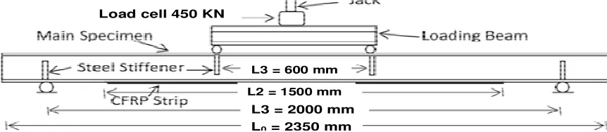
L3 = 600 mm
L3 = 2000 mm
L2 = 1500 mm
L0 = 2350 mm
Load cell 450 KN
Figure 2. Test setup and beam dimensions.
The objectives of this research: (a) To investigate the effectiveness of using CFRP strips to flexure strengthen steel I-beams, and (b) To examine the effects of using different thicknesses and Modulus of Elasticity of CFRP strips used in strengthening of steel I-beams. To investigate the aforementioned objectives, both experimental test and numerical simulation were employed.
MATERIALS AND METHODS
Steel beam
In this research, steel I-sections from grade A36 (ASTM) were strengthened by using CFRP plates. Table 1 shows the dimensions
and material properties of the steel beams, and Figures 1 and 2 indicate the section dimension of the specimens.
CFRP plate
Carbon fibre reinforcement polymer has been widely utilised to strengthen structural elements. CFRP has high tensile strength, and it is installed on the tensile region to improve the load bearing capacity of structures.
In this research, three types of CFRP materials are used (S, CF1, and CF2). The material properties of CFRP types of S and CF1 are the same, but they were produced by different manufacturer (Table 2). The CFRP type of S and CF1 are the high tension (HT) CFRP plates. This type of CFRP has high tensile strength (about 3000 N/mm2) and the modulus of elasticity is about 165000 N/mm2. The
1622 Int. J. Phys. Sci.
Table 2. CFRP plates dimensions and material properties.
CFRP type (Trade Mark) Dimensions (mm) (N/mmE-Modulus 2)Min. value (N/mmTensile strength 2) Min. value Strain at break
Width Thickness Length
Sika® CarboDur®
S512/80- Type S 50 1.2 1500 >160000 >2800 1.70 ±0.01
LaMaCo™ Build Seal®
514- Type 1CF (S) 50 1.4 1500 >165000 >3000 1.70 ±0.01
LaMaCo™ Build Seal®
[image:3.612.50.580.289.351.2]514- Type 2CF (M) 50 1.4 1500 >210000 >2400 1.90 ±0.01
Table 3. Adhesive dimensions and material properties (Sikadur® -30).
Dimension (mm) Compressive strength (N/mm2) Tensile strength (N/mm2) Shear strength
(N/mm2) Strength 7 days
Bond strength on steel (N/mm2)
Width Thickness Length E-Modulus Strength 7 days E-Modulus Strength 7 days Mean value value Min.
50 1.0 1500 9600 70-95 11200 24-31 14-19 30 >21
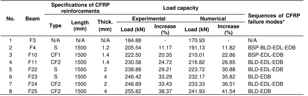
Table 4. Specifications, test and modelling results of the specimens.
No. Beam
Specifications of CFRP
reinforcements Load capacity
Sequences of CFRP failure modes* Type Length (mm) Thick.
(mm)
Experimental Numerical
Load (kN) Increase (%) Load (kN) Increase (%)
1 F3 N/A N/A N/A 184.88 - 170.93 - N/A
2 F4 S 1500 1.2 205.54 11.17 191.13 11.82 BSP-BLD-EDL-EDB
3 F10 CF1 1500 1.4 222.50 20.35 210.01 22.86 BSP-EDL-EDB
4 F11 CF2 1500 1.4 230.58 24.72 216.82 26.85 BLD-EDL-EDB
5 F22 S 1500 2 238.88 29.21 223.72 30.88 BLD-EDL-EDB
6 F23 S 1500 4 246.42 33.29 232.17 35.82 BLD-EDB
7 F24 CF2 1500 2 246.69 33.43 233.33 36.51 BLD-EDL-EDB
8 F25 CF2 1500 4 255.82 38.37 241.93 41.54 BLD-EDB
*BLD: Below load-debonding, EDB: End-debonding, BSP: Below load-splitting, EDL: End-delamination.
modulus of elasticity of 21000 N/mm2 (same as mild steel).
By comparison the results of applying these two kinds of CFRP (HT and IM), the effects of CFRP material properties on the flexural behaviour of steel beams are studied.
Adhesive
The CFRP plates were installed on the beam bottom flange by using the special epoxy type of Sikadur® -30. The epoxy must be strong to bear the high stress generated during loading (Schnrech et al., 2005, 2006). Nowadays, producing high strength epoxy is possible due to modern technology. The specification and material properties of the chosen adhesive are shown in Table 3 (SIKA
Product Information, 2008).
Specifications of the specimens
[image:3.612.52.574.395.558.2]Narmashiri et al. 1623
175 mm 700 mm 300 mm 300 mm 175
Figure 3. Strain gauges locations.
upgraded by using the CFRP type CF2 and the thicknesses of 1.4, 2, and 4 mm, respectively.
Preparation of the specimens
The following processes were carried out for the preparation of the specimens. Firstly, according to the SIKA®’s product instruction, surfaces were sandblasted in Swedish Standard SA 2.5. Then, the cleaned CFRP strips were glued to the bottom flange of the specimens. After one week, when the adhesive has hardened (SIKA Product Information, 2008) the test procedures were carried out.
Test setup
The experimental setup is based on the four-points bending test (Narmashiri et al., 2010). In order to measure strain, some strain gauges were installed in different regions of the specimens. Figures 1 and 3 show the locations and directions of strain gauges. Some strain gauges were installed along the length of the CFRP plate to measure the strain along the whole length of the plate.
The load was applied by using a hydraulic jack via a load cell of 450 kN capacity. The load was transferred from the jack to the main specimen by using a loading beam. The middle of the loading beam was subjected to jack pressure, and two symmetrical point loads were applied to transfer the load’s pressure to the main specimen (beam). Two roller supports carried the reactions; therefore, the loading state was four incremental bending points loads.
Numerical simulation
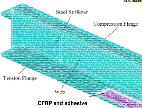
To model the specimens, the full 3D simulation using ANSYS software was performed. The steel I-sections, steel stiffeners, CFRP plates, and adhesive were simulated by using the 3D solid triangle elements (Ten-Nodes 187). The interface of common surfaces was defined between the steel I-beam, adhesive, and CFRP plates. Debonding and delamination occurred when the plastic strains exceeds the ultimate strain. Non-linear static analysis was carried out to achieve debonding and delamination. In this case, the load was applied incrementally until the plastic strain in the first element reached the ultimate strain. The linear and nonlinear properties of materials were defined. The CFRP plate material properties were defined as linear and orthotropic because CFRP materials have linear properties and they were unidirectional (Linghoff et al., 2009). The steel beams were defined as nonlinear properties. For meshing, combination of the auto meshing and map meshing were used. In the critical region, the elements were
[image:4.612.332.565.255.432.2]CFRP and adhesive
Figure 4. 3D simulated specimen.
meshed smaller than the other regions. Figure 4 shows a schematic of the 3D modelled specimen. Since, modelling the CFRP strengthened steel I-beams with the aforementioned approaches had sufficient accuracy to experimental test (Narmashiri and Jumaat, 2011); the same methods are used for this research.
RESULTS AND DISCUSSION
Failure modes
1624 Int. J. Phys. Sci.
Figure 5. Below point load splitting (BLS).
Figure 6. Below load debonding (BLD).
For the strengthened specimen F4, the following failure
modes were observed (Narmashiri et al., 2011):
1. Splitting below the point loads (Figure 5) 2. Debonding below the point loads (Figure 6) 3. Delamination at the CFRP tips (Figure 7) 4. Debonding at the CFRP tips (Figure 8)
One major problem of strengthened steel beams is the presence of high interfacial stresses near the end of the composite laminate which might govern the failure of the strengthening schedule (Haghani et al., 2009). Also, end-debonding was occurred because of high stress and strain intensity on adhesive at the CFRP tips (Deng and Lee, 2007a, b).
Figure 7. End delaminating (EDL).
Figure 8. End debonding (EDB).
Before yielding, the ends of CFRP reinforcement were more critical, but after yielding, the high stress also occurred at the mid-span (below point load) that caused below point loads debonding (Al-Emrani et al., 2005).
Another CFRP failure mode that occurred in this research is the end- delamination. An important feature of the reinforced beam is the significant stress intensity at the tip of CFRP plate because there is a discontinuity by the abrupt termination of the plate (Deng et al., 2004).
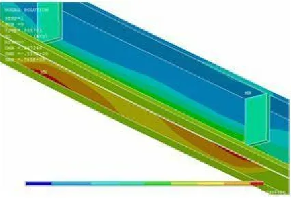
Figure 9. Stress intensity below point loads.
the asymmetrical stress intensity below the point loads (Figure 9). This stress intensity occurred due to a combination of the overall lateral-torsional-buckling and local buckling. Since, the lateral deformation was not prevented in this study, the beams deformed in both vertical and horizontal directions. This kind of stress distribution was symmetrical in the longitudinal direction (parallel to the beam’s axis), but it was asymmetrical in the transverse (perpendicular to the beam’s axis) direction. On the other hand, this failure happened due to weakness of CFRP in the transverse direction because fibres in CFRP plates are located in the longitudinal direction that caused high axial and low transverse strength of CFRP.
For the specimens that were strengthened by using thicker CFRP plate (1.4 and 2 mm), the following failure modes were observed (F10, F11, F22, and F24):
1. Below load-debonding 2. End- delamination 3. End-debonding
The below load-splitting problem was not seen for these specimens. It seems one of the most appropriate approach to increase the strength of beam against the following load-splitting was the increment of thickness of the CFRP plate.
For the strengthened specimens by using thicker CFRP plate (4 mm), the following failure modes were recognized:
1. Below load-debonding; 2. End-debonding.
This means when thicker CFRP plate was used (4 mm), then the CFRP showed brittle behaviour. On the other hand, the end-debonding was more significant than the end- delamination when the CFRP with 4 mm in thickness was used.
Narmashiri et al. 1625
Load bearing capacity
Table 4 indicates that by applying thicker CFRP plate (1.4, 2 and 4 mm) compared to (1.2 mm) type HT, the load bearing capacity increased significantly. Interestingly, by using only 0.2 mm, more thickness of CFRP (1.4 compared to 1.2 mm), the load capacity improved noticeably (8%). As mentioned previously, application of thicker plate can overcome the below load-splitting problem; this was the reason of increment in the load capacity.
The specimens F10-F11, F22-F24, and F23-F25 were strengthened by using the CFRP plates with the same thickness (1.4, 2 and 4 mm, respectively), but they have different material properties (HT or IM). Table 4 shows that applying IM-CFRP (F11, F24, and F25) caused more increment in the load capacity, due to larger elasticity modulus. On the other hand, higher modulus of elasticity caused higher load capacity.
Applying thicker CFRP plate (1.4, 2 and 4 mm compared to 1.2 mm) caused higher load capacity. For HT-CFRP, the increments included 8, 16 and 20%. Application of the CFRP plate with 4 mm in thickness increased the load capacity only 4% compared to the applying the thickness of 2 mm. This means that using very thick CFRP (4 mm) could not increased the load capacity significantly (concerning the applying twice thickness compared to 2 mm in thickness of plate). The reason is premature debonding due to generating high strain on adhesive in case of applying thicker plate (4 mm).
Finally, application of thicker CFRP plate increased the load bearing capacity significantly to overcome the below load-splitting failure, but applying the thickest CFRP plated caused premature debonding. Module of elasticity influenced the load capacity, and using higher module of elasticity caused improvement in the load bearing capacity.
Strain on CFRP plate
Figures 10 to 12 show strain along the length of CFRP plate for three different load levels of 100, 150 and 180 kN (achieved by experimental tests). They illustrate that at the load level of 100 kN (Figure 10), there was no differences between the results of strain for different thickness and types of CFRP plate.
At the load level of 150 kN (Figure 11), strain for F10 at the end of plate and below the point loads was less than strain on CFRP for the specimens F4 and F11. This means applying thicker CFRP plate (F10 compared to F4) caused reduction in strain. Also, using CFRP plate with higher tensile strength (F10 compared to F11) caused reduction in strain significantly.
[image:6.612.65.278.93.238.2]1626 Int. J. Phys. Sci.
Figure 10. Strain on CFRP plate for the load level of 100 kN.
Figure 11. Strain on CFRP plate for the load level of 150 kN.
thicker plate (F10 compared to F4) and CFRP with higher tensile strength (F10 compared to F11) caused reduction of strain on CFRP plate at the end of plate and below the point loads significantly. These reductions for both specimens F10 and F11 were approximately the same. This means, at higher load levels, the thickness of CFRP plate was more effective than elasticity modulus to reduce the tension strain on CFRP.
At last, application of thicker CFRP decreased the strain on CFRP plate below the point loads and at the end of plate considerably (especially for higher load). In addition, using CFRP with higher tensile strength, at lower load (150 kN) caused more reduction in strain on CFRP plate, but at higher load (180 kN) the effects of applying HT and IM CFRP was approximately the same.
Conclusions
In conclusion, this study has shown that flexural behaviours of steel I-beams are improved using CFRP strips. The application of different thicknesses and types of CFRP plates used in strengthening steel I-beams caused change in the CFRP failure modes, load bearing capacity, and strain on CFRP plates. One of the most efficient approaches to increase the strength of beam against the below load splitting was by increasing the CFRP thickness. Applying a thicker CFRP plate caused significant increment in the load bearing capacity, but the CFRP showed brittle behaviour, and premature end debonding occurred. Application of the IM-CFRP plates caused considerable increment in the load bearing capacity, due to the larger elasticity modulus.
ACKNOWLEDGMENT
It is gratefully acknowledged that the study presented here is financially supported by the University of Malaya and Islamic Azad University, Zahedan Branch.
REFERENCES
Al-Emrani M, Linghoff D, Kliger R (2005). Bonding strength and fracture mechanisms in composite steel-CFRP elements. International Symposium on Bond Behaviour of FRP in Structures (BBFS 2005), International Institute for FRP in Construction.
Al-Emrani M, Kliger R (2006). Experimental and numerical investigation of the behaviour and strength of composite steel-CFRP members. Adv. Struct. Eng., 9: 819-831.
Narmashiri et al. 1627
Buyukozturk O, Gunes O, Karaca E (2004). Progress on understanding debonding problems in reinforced concrete and steel members strengthened using FRP composites. Constr. Build. Mater., 18: 9-19. Chiew S P, Lie S T, Lee C K, Yu Y (2005). Debonding failure model for
FRP retrofitted steel beams. Fourth International Conference on Advances in Steel Structures, Shanghai, China.
Deng J, Lee MMK (2007a). Behaviour under static loading of metallic beams reinforced with a bonded CFRP plate. Comp. Struct., 78: 232-242.
Deng J, Lee MMK (2007b). Fatigue performance of metallic beam strengthened with a bonded CFRP plate. Comp. Struct., 78: 222-231. Deng J, Lee MMK, Moy SSJ (2004). Stress analysis of steel beams
reinforced with a bonded CFRP plate. Comp. Struct., 65: 205-215. Haghani R, Al-Emrani M, Kliger R (2007). Control of Interfacial Stresses
in Beams Strengthened with Prestressed CFRP Laminates. Asia-Pacific Conference on FRP in Structures (APFIS 2007), Hong Kong, China.
Haghani R, Al-Emrani M, Kliger R (2009). Interfacial stress analysis of geometrically modified adhesive joints in steel beams strengthened with FRP laminates. Constr. Build. Mater., 23: 1413–1422.
Hollaway LC, Zhang L, Photiou NK, Teng JG, Zhang SS (2006). Advances in Adhesive Joining of Carbon Fibre/Polymer Composites to Steel Members for Repair and Rehabilitation of Bridge Structures. Adv. Struct. Eng., 9: 791-803.
Linghoff D, Haghani R, Al-emrani M (2009). Carbon-fibre composites for strengthening steel structures. Thin Wall. Struct., 47: 1048-1058. Narmashiri K, Zamin Jumaat M (2011). Reinforced steel I-beams: A
comparison between 2D and 3D simulation. Simul. Model. Pract. Theory, 19: 564-585.
Narmashiri K, Zamin Jumaat M, Ramli Sulong NH (2010). Investigation on end anchoring of CFRP strengthened steel I-beams. Int. J. Phys. Sci., 5: 1360-1371.
Narmashiri K, Zamin Jumaat M, Ramli Sulong NH (2011). Failure modes of CFRP flexural strengthened steel I-beams. Key Eng. Mater., 471-472: 590-595.
Schnerch D, Dawood M, Sumner E, Rizkalla S (2006). Dseign guidlines for strengthening of steel-concrete composite beams with high modulus CFRP materials. 7th. International Conference on Short and Medium Span Bridges.
Schnerch D, Stanford K, Sumner E, Rizkalla S (2005). Bond behavior of CFRP strengthened steel bridges and structures. International Symposium on Bond Behaviour of FRP in Structures (BBFS 2005), International Institute for FRP in Construction.
SIKA Product Information (2008). Second ed., Sika® Kimia Sdn Bhd., Kuala Lumpur.