ISSN Online: 2331-4249 ISSN Print: 2331-4222
Methodology for the Study of the Quality of
CFRP Dry Drilling Based on Macrogeometrical
and Dimensional Deviations
J. Salguero
*, S. R. Fernandez-Vidal, P. Mayuet, J. M. Vazquez-Martinez, M. Alvarez, M. Marcos
Mechanical Engineering and Industrial Design Department, University of Cadiz, Cadiz, Spain
Abstract
Commonly, Carbon Fiber Reinforced Plastics (CFRP) aerospace elements need to be machined (drilling) for subsequent assembly operations, mainly riveting, taking a critical importance the quality requirements of the holes. Some of the adjustment defects that can be produced during the dry drilling of CFRP are related to macro-geometrical (diameter, D, and cylindricity, DC) deviations. This paper reports on the results of a study of the influence of the cutting parameters V (cutting speed) and f (feedrate) on the D and DC deviations in the dry drilling of CFRP. A particular pro-cedure based on plastic hole replicas has been performed. Diameters deviations were acceptable in all the cases studied. Because of this, DC is the controlling factor for accepting the drilled holes. In the studied range, lowest cutting speeds and highest feedrates have allowed obtaining the minimum cylindricity deviation.
Keywords
Dry Drilling, CFRP, Macrogeometrical Deviations, Cylindricity, Diameter
1. Introduction
Control of the aircraft’s weight is one of the main mandatory contractual points for the aerospace companies, being reviewed in reference to two values; Not to Exceed Weight (NTEW) and Target Weight (TW). If the NTEW is exceeded then $1000/kg per aircraft must be paid to the final client, while if the aircraft manufacturers manage to go below the TW, final clients pay them a bonus of $500/kg in each aircraft [1]. In this search for reducing weight, and so emissions and fuel efficiency, composite materials have played a key role. Currently there are three main types in use: carbon, glass and aramid fiber reinforced epoxy, classified into the so-named Fiber Reinforced Plastics (FRP) [2] [3]. How to cite this paper: Salguero, J., Fer-
nandez-Vidal, S.R., Mayuet, P., Vazquez-Mar- tinez, J.M., Alvarez, M. and Marcos, M. (2016) Methodology for the Study of the Quality of CFRP Dry Drilling Based on Mac- rogeometrical and Dimensional Deviations. World Journal of Engineering and Techno- logy, 4, 200-205.
http://dx.doi.org/10.4236/wjet.2016.43D024
Nevertheless carbon fiber is the reinforcement material of choice for “advanced” com-posites, because it exhibits excellent fatigue resistance which do not suffer from stress rupture compared with glass or aramid fibers. This kind of advanced material is com-monly called as Carbon Fiber Reinforced Plastic or Polymer (CFRP) [2].
Structural parts made of CFRP have frequently to be drilled and riveted afterwards during the assembly operations. So, machining processes have to guarantee the tight dimensional and geometric tolerances specified in the quality requirements [4] [5]. Usually, the damages of drilling FRPs are classified into four categories: delamination at entry, geometric defects, temperature-related damages and delamination at exit [6]. Among the geometric defects, control of cylindricity errors, together with the diameter deviations, are key factors in major aerospace manufacturers, due to these are directly related to the correct assembly and proper functioning of the rivets [7] [8].
When CFRP is drilling, the tool geometry related damages are associated to the angle between fibers orientation and the cutting edge [9]. This occurs due to the fact that be- fore shearing takes place, the fibers are subject to alternate torsion and compression, resulting on an elliptical hole, in which the smaller axis of the ellipse is in the same di-rection of the fibers and is inferior to the drill diameter [10]. On the other hand, cutting tool wear in the dry drilling of CFRP is mainly based on abrasion mechanism, in which the cutting tool gradually lose its initial geometry, and so affecting to all the features involved in the geometrical and dimensional tolerances [11].
Majority of the researches in the domain of geometrical tolerances are done for vari-ous types of errors associated in achieving these tolerances. The error compensation strategies are also developed, and various innovative models and techniques were de-veloped to measure various geometrical tolerances. However, the work related to cut-ting parameters, its investigation, its contribution and its selection to optimize the geometrical errors need some amount of focus. In this paper, a preliminary study of the influence of the cutting parameters on the holes quality has been developed. Dimen-sional deviations (taking as reference the difference between measured and nominal hole diameters) and cylindricity deviations (as a macrogeometrical deviation para-meter that combines the effect of roundness, straightness and parallelism deviations) have taken as a measurement of the holes macro-quality in the dry drilling of CFRP sheets.
2. Experimental Methodology
The experimental procedure contains two sequential stages:
1) Design and development of drilling test, including technological parameters selec-tion, clamping device design and drilling cycles programming.
2.1. Dry Drilling Tests
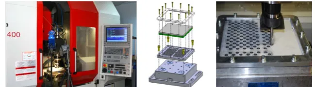
210 × 210 × 4.5 (mm) sheets of CFRP (34% epoxy) with (0/90/45/-45/45/-45) layer orientation, have been used as test material for being drilled. Uncoated SANDVIK VUS85CS0377 WC-Co drills have been used as cutting tools, Table 1. Dry drilling tests were conducted in a High Speed Machining Center (HSMC) Kondia Five 400, equipped with a Heidenhain iTNC-530 CNC. A special tooling equipment were applied for clamping the samples, Figure 1. The dry drilling tests were performed combining two extreme values of cutting speed (V) and feedrate (f) selected from previous work de-veloped on this kind of materials. A cutting speed of 85 m/min and feedrate of 250 mm/min were selected from the cutting-tool manufacturer. Also, a higher cutting speed of 145 m/min and a higher feedrate of 400 mm/min were selected in order to obtain a widest range of results in a high productivity rate, although in a more aggressive cutting conditions. So, a total of 4 tests have been conducted, taking into account all the possi-ble combinations V-f. As this is a preliminary study, only a set of 25 drills has been car-ried out in each one of the dry drilling tests, using new cutting tools for each test.
2.2. Metrological Evaluation
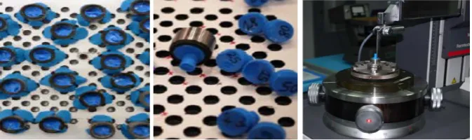
Hole diameters were evaluated by using a millesimal Mitutoyo Digimatic 3-contacts bore micrometer, measuring at 3 levels equispaced 120˚. Experimental diameter value was taken as the average of the three recorded values. Cylindricity deviations were eva-luated using a Mahr Formtester MMQ 44, as the average deviation of 6 roundness measures along the body of the hole. For this purpose, and due to the geometry of the drilling samples, a Plastiform RGX 80 resin was use to obtain a replica of each hole, Figure 2. This procedure has been validate by aerospace companies geographically close to our labs.
[image:3.595.210.535.457.547.2]
Figure 1. Kondia Five 400 (left). Detail of tooling (center). CFRP drilling process (right).
Table 1. Cutting toolgeometrical parameters.
DC
Figure 2. Resin curing process inside the holes (left). Samples for cylincricity measurement (cen-ter). Mahr Formtester MMQ 44 (right).
3. Results and Discussion
Figure 3 plots the evolution of the measured diameters as a function of the number of holes, for each cutting speed used. Two reference horizontal lines have been included. Lower line defines the nominal diameter based on the average diameter of cutting tool. Upper line defines the maximum admitted value (tolerance) in the recent Airbus A350 XWB program. This defines a tolerance range of 64 µm.
As it can be observed, all the values can be accepted because they are placed into the tolerance range. All the D values are higher than D0. This is associated to the plastic compression of CFRP. The influence of the cutting temperature does not seem be af-fected with the machining time because it cannot be detected appreciable changes with the number of holes (N). However, cutting speed (V) provokes a soft increase of the values of D that can be associated to the thermal expansion of the carbon fibers, which like others temperature-related damages [6], has a strong dependence on the cutting speed [8]. On the other hand, in a very fine analysis, a very soft decreasing of the D(N) branches value of the diameter with the number of holes can be detected. Although the number of drilling is only 25, it can be related to the tool wear. In effect, as it can be observed in the SEM images of drilling tools included in Figure 4, slight signs of abra-sive wear can be distinguished. This kind of wear can diminished the average diameter of the tool and it can provoke a negative evolution of D (N) values.
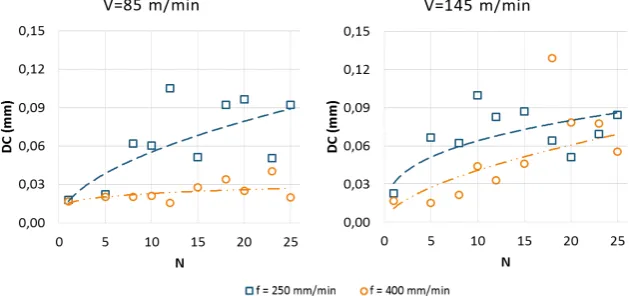
Figure 5 plots the evolution of cylindricity deviation, DC, as a function of the num-ber of drills (N) for the different cutting parameters applied.
Figure 3. Diameter (D) evolution as a function of the number of drills (N).
Figure 4. SEM images of the cutting tool after 25 holes (V = 85 m/min, f = 250 mm/min). Rake face (left). Margin (center). Clearance face (right).
[image:5.595.216.531.390.538.2]
Figure 5. Cylindricity deviation (DC) evolution as a function of the number of drills (N).
4. Conclusion
Acknowledgements
This work has been funded by the Spanish Government (Project DPI2015-71448-R), from the European Union (FEDER/FSE) and from the Andalusian Government (Pro- ject DIANNA-INTERCONNECTA). Authors want to thank to AIRBUS D&S the col-laboration in the research associated to this paper.
References
[1] Sánchez, A. (2016) Weight Control on A350 XWB. Alestis Aerospace Newsletter, 4, 20. http://www.alestis.aero/wp-content/uploads/2016/05/Flying-N4-WEB.pdf
[2] Rosato, D.V. and Rosato, D.V. (2004) Reinforced Plastic Handbook. 3rd Edition, Elsevier, Oxford.
[3] Bunsell, A.R. and Renard, J. (2005) Fundamentals of Fiber Reinforced Materials. Institute of Physics Publishing, London. http://dx.doi.org/10.1201/9781420056969
[4] Mayuet, P., Gallo, A., Portal, A., Arroyo, P., Alvarez, M. and Marcos, M. (2013) Damaged Area Based Study of the Break-IN and Break-OUT Defects in the Dry Drilling of Carbon Fibre Reinforced Plastics (CFRP). Procedia Engineering, 63, 743-751.
http://dx.doi.org/10.1016/j.proeng.2013.08.249
[5] Yan, Q.B. and Chen, W.L. (2015) Automatic Modification of Local Drilling Holes via Dou- ble Pre-Assembly Holes. World Journal of Engineering and Technology, 3, 191-196. http://dx.doi.org/10.4236/wjet.2015.33C028
[6] Lachaud, F., Piquet, R., Collombet, F. and Surcin, L. (2001) Drilling of Composite Struc-tures. Composite Structures, 52, 511-516.
http://dx.doi.org/10.1016/S0263-8223(01)00040-X
[7] Drake, P.J. (1999) Dimensioning and Tolerancing Handbook. McGraw-Hill, New York. [8] Sheth, S. and George, P.M. (2016) Experimental Investigation, Prediction and Optimization
of Cylindricity and Perpendicularity during Drilling of WCB Material Using Grey Relation-al AnRelation-alysis. Precision Engineering, 45, 33-43.
http://dx.doi.org/10.1016/j.precisioneng.2016.01.002
[9] Abrao, A.M., Faria, E.E., Campos Rubio, J.C., Reis, P. and Davim, J.P. (2007) Drilling of Fi-ber Reinforced Plastics: A Review. Journal of Materials Processing Technology, 186, 1-7. http://dx.doi.org/10.1016/j.jmatprotec.2006.11.146
[10] Inoue, H., Aoyama, E., Hirogaki, T., Ogawa, K., Matushita, H., Kitahara, Y. and Katayama, T. (1997) Influence of Tool Wear on Internal Damage in Small Diameter Drilling in GFRP. Composite Structures, 39, 55-62. http://dx.doi.org/10.1016/S0263-8223(97)00068-8
Submit or recommend next manuscript to SCIRP and we will provide best service for you:
Accepting pre-submission inquiries through Email, Facebook, LinkedIn, Twitter, etc. A wide selection of journals (inclusive of 9 subjects, more than 200 journals)
Providing 24-hour high-quality service User-friendly online submission system Fair and swift peer-review system
Efficient typesetting and proofreading procedure
Display of the result of downloads and visits, as well as the number of cited articles Maximum dissemination of your research work
Submit your manuscript at: http://papersubmission.scirp.org/