2018 International Conference on Computer, Communication and Network Technology (CCNT 2018) ISBN: 978-1-60595-561-2
Indoor Simultaneous Localization and Mapping for Lego Ev3
Qiang CHEN
1,2, Yi-nong CHEN
2,*,
Peng TANG
1, Ran CHEN
3,
Zhi-na JIANG
3and
Ai-bo DENG
31
College of Computer and Information Science, Southwest University, Chongqing, China 2
School of Computing, Informatics and Decision Systems Engineering, Arizona State University, Tempe, AZ, USA
3
Chongqing Songshuqiao Middle School, Chongqing, China
*Corresponding author
Keywords: Autonomous car, SLAM, Lego Ev3, Object detection, Image processing.
Abstract. Simultaneous localization and mapping (SLAM) function is a key component for the indoor robot. Many researchers use the Laser Imaging Detection and Ranging (LIDAR) or depth camera to enhance the mapping process. However, LIDAR and depth camera are so expensive, so the image based SLAM algorithm becomes the first choice of SLAM. Visual SLAM only use image information to detect object, but the process is time-consuming, and usually it comes with low precise. In this paper, we propose a SLAM algorithm with the help of ultra sound data, gyroscope data and an ordinary camera on an Android phone. Although the camera does not provide any depth information for mapping, we use combine the ultra sound, gyroscope data and the image information to enhance the mapping process. Moreover, we use deep learning algorithm to detect the object in the image, and then use the information to refine the map. Experimental results show that the proposed algorithm can effectively improve the quality of the map.
Introduction
There are three main key functions for an indoor robot or autonomous car: localization, mapping and routing [1]. First, a frequently updated map is needed for the robot. The reason is that without the map robot may have no idea about the environment and cannot find the destination. Second, robot needs some extra information to localize its position, and then matches the location in the map. Finally, robot will plan a routing to avoid the obstacle and manage to reach the destination with the help of simultaneous localization and mapping. Therefore, the simultaneous localization and mapping is a key function for an indoor robot [2].
With the progress of high precise Laser Imaging Detection and Ranging (LIDAR) [3] sensors, researcher can use it to map the environment more conveniently. Unfortunately, LIDAR is a high-energy consuming and expensive device, we cannot use the LIDAR directly in a scene with which surround some robots like Lego and Raspberry PI. Therefore, some researcher try to use camera to get information for building a map, but building map from ordinary mono camera is still a challenging task. Usually they will use RGB camera, stereo camera or RGB-D Kinect depth sensor [4] to build a map simultaneously. The reason why they use other high-end camera than ordinary camera is that the ordinary camera cannot provide any depth information, which is key to mapping progress. In recent year, there emerges so many mapping algorithm based on mono ordinary camera [1]. The main idea of the algorithm is listed as follows. First, select some salient features. Second, match the feature appeared in previous frames to calculate out the moving distance. Finally, do loop closure detection to eliminate the redundancy and inconsistency of the map. However, the process mentioned above is time consuming, and usually it comes with low precise.
without any extra charges. Second, we use an Android phone to provide an ordinary camera for the program, also without any cost. The Android phone is connected Lego Ev3 through the Bluetooth, the App running on the Android phone will collect Ev3’s sensor data and images from Android phone, and then send the data to a laptop or PC. We use Ev3 and camera to get the distance information and the image of the obstacle, and then we try to estimate out the depth information. Finally, with the help of Android phone, we can use some high-end techniques such as Deep Learning algorithm [5] to detect the object, and then recognize the object. Once we have the basic knowledge of the obstacle, we can use this information to build a higher precise map even without any depth camera or LIDAR.
The rest of the paper is organized as follows. Section 2 gives the detail information of the proposed Indoor simultaneous localization and mapping (SLAM) system. Section 3 analyses the experimental results and lists some idea for the future work. The last section concludes the paper.
Indoor Simultaneous Localization and Mapping for Lego Ev3
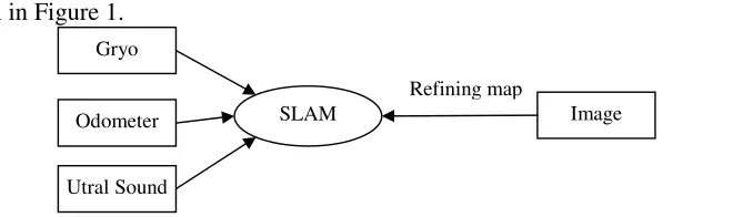
[image:2.612.152.482.265.363.2]In this section, we discuss the basic idea of the proposed mapping system. The framework of the system is shown in Figure 1.
Figure 1. Framework of the simultaneous localization and mapping system.
GPS is helpful for localization, but it is difficult to use GPS in an indoor environment. Therefore, we should build the map and do localization while travelling through the environment. In this paper, the simultaneous localization and mapping progress contains at least three key component, coarse mapping building, refining map with Ultra Sound data and localization and refining the map by object detection algorithm. The following sections give the details.
Coarse Mapping Building
In the first step, we build a coarse map by using the data from Lego Ev3 exclusively. Since we didn’t know the exact location of the robot, we will just draw the start point in the middle of our map. When the robot was moving forward, we will periodical move the robot’s current position to a new coordinate. It will display on the map and reflects as a moving object. We need two sensor data to complete the coarse map: odometer and gyroscope data. The mapping progress is listed as follows.
Step1. Recording the initial angle as a0, setting a fixed step δ used to calculate the unit moving distance.
Step2. In a new location, recording the angle as a1, using Eq.1 to calculate the coordinate of the new location.
a= α1-a0
x=x0+cos(a)* δ
y=y0-sin(a)* δ (1) where a is the variation of the angle detected by the gyroscope sensor, a0 is the previous angle and a1 is the current angle, x0, y0 is the previous x, y coordinate of the location respectively. The x and y is used to draw the new location on the map, δ is a fixed predefined moving step, and we usually set it as 1 pixel. We will update the location every half second when robot is moving. However, we can conclude from the above to infer that the precise is very low; the updated location has nothing to do
SLAM Gryo
Odometer
Utral Sound
Refining map
with the real moving distance of the robot. Therefore, we will use the odometer data to refine the moving distance, which will be reflected in the map. We define the odometer as dl and dr respecting for the left-wheel, right-wheel running distance respectively, and then we update the new coordinate by using Eq.2.
δ' =Wm*((dl + dr)/2/Wr) (2) where Wm the length of map in pixels (we assume the environment as a square.), Wr is the length of the real scene which also under the assuming that the environment is a square. We use δ' to replace δ in Eq.1, and then get the coordinate of the new location. The mapping program will jump to Step1 until robot stopped.
Refining Map with Ultra Sound Data
The odometer data used above is not enough to reflect the real moving distance of the robot when the robot is stopped by an obstacle. In such situation, the wheel is turning but without making the robot moving forward, so the odometer is unacceptable at this time. Therefore, we need another sensor’s data to refine the map in order to avoid unbelievable mapping progress.
Here, we use Ultra Sound data to refine the mapping progress in case of the robot is stopped by some obstacle. The max distance for an Ultra Sound sensor installed on EV3 is 255cm. If the distance is less than 255cm, then we can use it to refine the map. The procedure is listed as follows.
Step1.If the distance is less than 255cm, recording it as d0.
Step2.After one second, recording the new distance and denoting as d1.
Step3.If the absolute value of d1 minus d0 is less than 0.1cm, then notifying the App not to update the map. Go to Step1.
Here, the ultra sound data is only used for a particular situation while the robot stopped by an obstacle. In the next section, we will use it together with the image to refine the map and to localize the location of the real scene.
Localization andRefining the Map by Object Detection Algorithm
In this section, we will use object detection algorithm to detect an obvious object in our environment, and then use it to tackle with the loop closure problem in SLAM. To simplify the problem, we put some distinct, regular objects in our environment, such as boxes, computer cases, another Lego Ev3, some simulated traffic signs posted on the wall and trash bins. We cannot use irregular objects, more specifically, object with holes cannot be used to pretend the obstacle. For example, the chair is not a suitable obstacle in our framework because the Ultra Sound data may not reflect the real distance between them. The ultra sound will go through the chair without any reflection, so we cannot get the real reading. The whole procedure is listed as follows.
Step1. Detecting and recognizing the object in front of the robot. If it is an object that we predefined, then recording the distance reading.
Step2. Moving forward for a while, if the detected object remains in the scene, and the distance data also changes a little, then we think this is a fixed point. We use the detected object to localize robot’s location.
Step3. When meeting with other predefined objects, recording the location (the coordinate and the direction).
Step4. When revisiting an object, refining the map, and trying to estimate the whole scene.
Experimental Results
and Visual Studio 2013 to build application that running on PC. Meanwhile, we use python 3.5.2, tensorflow1.5.0 CPU version and MobileNetV1[5] to detect the obstacle.
Experiment Setting and Results
After exhaustively research, we empirically set δ as 1 for Eq.1.Figure 2 depicts the obstacle detection
results. Figure 2(a) is a computer case, Figure 2(b) is a chair. The detection result in Figure 2(c) is wrong, it should be a computer case, but the algorithm outputs it as a trash bin, while the real trash bin is listed in Figure 2(d).
[image:4.612.77.532.175.277.2](a)Computer case. (b)Chair. (c) Should be a computer case. (d) Trash bin.
Figure 2. Obstacle detection results.
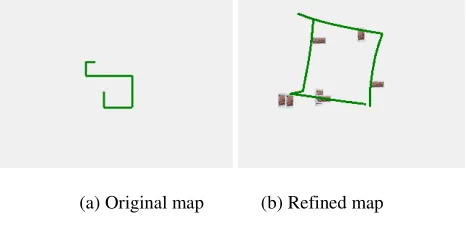
We use the obstacle detected by the MobileNetV1 to refine our map. Figure 3 shows the map before and after of refining. Figure 3 (a) depicts the original map, to which be built with the help of odometer, ultra sound and gyroscope sensor, Figure 3 (b) shows the refined map with the help of detected obstacles. However, we can see that the robot cannot go straightly in Figure 3 (b). This is not the mapping error, but it reflects the real path that the robot has passed. In order to solve this problem, we may choose some four-wheel drive car to replace it. Meanwhile, you can see there are some errors while drawing the bricks, so we should keep on improving the accuracy of the mapping process.
(a) Original map (b) Refined map
Figure 3. Map comparison.
In Figure 3 (b), we use a small brick to simulate the obstacle that we have detected, and then depict them in the map. It looks more realistic after we drew the bricks on the map. In the future work, we will add more detail information in the map in order to make the map reflect the real scene.
Discussions
[image:4.612.190.423.412.528.2]Summary
In this paper, we mainly talk about building a map with the help of several sensors. First, we use odometer and gyroscope data to build a coarse map, but the map is not as accurate when an obstacle stopped the car. Second, we use ultra sound data to solve the stopped car problem. We will periodically detect the distance in front of the car (EV3), if the car did not move forward in a predefined time, and then we conclude it may be blocked. Finally, we use image processing, especially, the deep learning algorithm to detect the obstacle in our environment, and then we use the object detected by the deep learning algorithm to refine the map. The experimental results show that the proposed mapping strategy can draw the map more precisely.
Acknowledgement
This research was financially supported by the China Scholarship Council (CSC 201706995087), ChuYing Plan of Chongqing (CY170217) and the Education Reform Project in Southwest University (2017JY094).
References
[1]J. Fuentes-Pacheco, J. Ruiz-Ascencio, J. M. Rendón-Mancha, Visual simultaneous localization and mapping: a survey. Artificial Intelligence Review, 43(1)(2015)55-81.
[2]C. Cadena, L. Carlone, H. Carrillo, Y. Latif, Past, present, and future of simultaneous localization and mapping: Toward the robust-perception age. IEEE Transactions on Robotics, 32(6) (2016) 1309-1332.
[3]M. G. Ocando, N. Certad, S. Alvarado, and Á. Terrones, Autonomous 2D SLAM and 3D mapping of an environment using a single 2D LIDAR and ROS. In Robotics Symposium (LARS) and Brazilian Symposium on Robotics (SBR), 2017, pp. 1-6.
[4]I. Z. Ibragimov, I. M. Afanasyev, Comparison of ROS-based Visual SLAM methods in homogeneous indoor environment. In Positioning, Navigation and Communications (WPNC), 14th Workshop, 2017, pp. 1-6.