2019 International Conference on Computer Science, Communications and Multimedia Engineering (CSCME 2019) ISBN: 978-1-60595-650-3
Design and Implementation of an Industrial Intelligent Infrared
Remote Controller
Xue-ying HAN, En-dian HU and Xing SU
School of Computer Science and Engineering, North Minzu University, 750021, CHINA
Keywords: MSP430f2111, Intelligent infrared remote control, Low power, Fuzzy control algorithm, Compressed pulse width counting.
Abstract. Aiming at the problems of the traditional electric actuator in the field of plant control, such as low control accuracy, low reliability and the unsuccessful debugging process, an intelligent infrared remote control system with MSP430F2111 as the core controller is designed. In the design, fuzzy clustering and structure recognition mean compression pulse width counting algorithm are used to identify and classify the collected remote control coded data effectively, which solves the problems of limited storage space, low transmission rate and high power consumption in the remote control system. UART (Universal Asynchronous Receiver/Transmitter) protocol is used to communicate with the electric actuator, and its status information and data information are displayed on the LCD (Liquid Crystal Display) screen, which improves the transmission rate and accuracy of the whole electric actuator system. On this basis, the overall structure of the system and the corresponding functional modules are designed. Finally, the coding simulation test is carried out through the software platform. The practice results show that the remote controller can control the electric actuator quickly and stably, and the simulation results are in good agreement with the field debugging results.
Introduction
In order to collect data on site and modify operation instructions, the traditional industrial electric actuator must open the shell of the electric actuator to view, which is extremely inconvenient for the operator, and has low efficiency and reliability. At the same time, there are many types of infrared remote controllers in China, but some remote controllers use special transmitter chips. Special chip has high power consumption, high cost and high integration, which is not conducive to large-scale promotion for small enterprises. Compared with other chips, this intelligent infrared remote controller not only has the advantages of large memory, low power consumption, good accuracy, low cost, good reliability and high processing speed, but also has its own unique advantages: ultra-low power consumption [1]. Based on the above background, a low-power intelligent infrared remote controller with MSP430F2111 as the core control chip in the industrial field is designed. Because its design operator can not only effectively control the working state of the electric actuator, but also play an important role in the daily maintenance and real-time fault monitoring of the whole system. This application will play a positive role in promoting the infrared remote control market.
Introduction of Low Power Chip Function of Infrared Remote Controller
remote control mainly completes the following functions: Infrared remote control should control and display the given value and setting parameters of the valve of electric actuator; Fault information is displayed through infrared feedback when internal faults occur in the system; Data Acquisition and Recognition Processing.
Block Diagram of Hardware Circuit System
MSP430F2111 chip as the control core mainly receives the key information transmitted by the key module, converts the key information into coding, then modulates and amplifies the 38kHz PWM(Pulse Width Modulation) wave and coding information to the receiving MCU(Micro Controller Unit) through the infrared transmitting module, and then displays it by the receiving MCU. The infrared remote control transmitting circuit is the core module of the system hardware circuit, which includes the following parts: key circuit, power circuit, clock circuit, reset circuit, infrared transmitting circuit; infrared information receiving and displaying circuit includes MSP430 microcontroller, 12864LCD(Liquid Crystal Display) display circuit and so on. The block diagram of the overall hardware circuit system is shown in Figure 1.
MSP430F 21111 Microcont roller Receiver MSP420 F249 Microco ntroller Infrared transmi tter module Power supply circuit 12864 LCD Display Module ResetCircut Clock Circuit Failure indicator data line signal line Address Line JTAG interface module Key module Infrared Transmitting Circuit
[image:2.595.180.418.295.456.2]Infrared Information Receiving and Displaying Circuit
Figure 1. Block diagram of overall hardware circuit system.
According to the characteristics of low voltage power supply (1.8-3.6V) of MSP430F2111 chip, the I/0 port of power supply circuit adopts low voltage power supply. The minimum power consumption of clock-off mode is only 0.1uA, and the voltage only needs a button battery of 3V. Clock circuit is to provide the clock signal circuit of microcontroller. Because the supply voltage VCC is larger than 2.8V, it needs to work in high-frequency mode. So the external 3.8MHz high-speed crystal oscillator is connected. At this time, the other two pins are connected with two small capacitors of 22pf, which not only reduces the cost of the system, but also reduces the power consumption of the system. The reset circuit is designed with the reset chip MAX810 of the special integrated circuit microprocessor. The chip can not only provide the reset signal of power on, manual reset of keys and automatic reset signal of timing, but also monitor the power supply voltage of the single chip computer and other logic systems. MAX810 resets the output signal to a high level.
In the actual industrial production, remote controllers are mostly short and compact. Independent key-press design is adopted in the key-press circuit, and each key has different functions. Four keys cooperate with each other to display the contents of the main menu and submenu. Functional keys as preparatory keys fail to return directly to the main menu.
Implementation of Key Hardware Technology
Infrared Emission Circuit and Reset Circuit
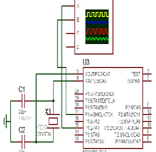
[image:3.595.220.377.325.477.2]The infrared transmitting circuit uses MSP430F2111 chip, which has good low power performance. The whole system is dormant when no key is pressed. Only when the key is pressed, the system is in working state to send data. In order to improve the anti-jamming performance, the repetitive transmission mode of wide and narrow pulse with pilot code is adopted [3]. Because the interruption between the measured and actual values of high and low levels will bring errors, the fuzzy clustering algorithm is used to classify the infrared signal data. Infrared remote control pulse data can be divided into three categories: boot code, high-level data code "1", low-level data code "0". In this design, the pulse of infrared remote controller is received by MSP430F249, which receives remote control information. The code stream of remote control data is longer, the transmission time of upper and lower computers is too long, and the efficiency is greatly reduced. Therefore, in order to improve the transmission rate, the similar characteristic components of the width and time interval of the remote control data pulse are selected to re-encode the data code. Infrared signal transmission uses TIMER-A continuous counting mode and UP/DOWND mode to configure PWM wave. In order to see the infrared emission waveform more clearly, an oscilloscope is added to Proteus simulation to detect the waveform. The output and transmission circuit of 38KHZ signal is shown in Figure 2.
Figure 2. Signal Output Transmitting Circuit.
Infrared Receiving Circuit
Figure 3. Infrared Receiving Hardware Circuit.
12864 LCD Display Circuit
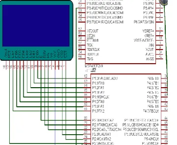
LCD dot matrix screen uses the model WYM12864K9 LCD screen. It uses ST7567 as the main control program and uses 4-line serial interface to transmit data[5]. The LCD screen receives and displays the actual opening of the valve, fault information, operation status and the opening set by the valve through serial communication. It can also set up an icon display with special symbols on the LCD screen. Because MSP430F249 cannot set the main clock as the timing clock source of MCLK, it can only set the auxiliary clock SMCLK as the timing clock source. The hardware connection diagram between 12864 LCD display screen and MSP430F249 single chip computer is shown in Figure 4.
Figure 4. Hardware Connection Diagram between Display Screen and MSP430F249 Single Chip Microcomputer.
Software Design of the System
The software development environment used in the development process is the integrated development environment of IAR Company. The development and debugging environment IAR writes code in C language. The software has its own functions of running, debugging and testing. The user's work efficiency is improved by using embedded IAR tools.
Main Program Flow Chart Design
[image:4.595.213.394.394.542.2]Data Acquisition Function Designated Header File
Watchdog Clock Port Initialization
Execute the while loop
Does the P1port havepulses?
End
Y
Output decoding code subprogram
N
start
Pulse Data Acquisition
[image:5.595.239.356.69.303.2]Data Compression Subprogram
Figure 5. Main Program Flow Chart of Remote Controller.
Data Acquisition and Compression Programming
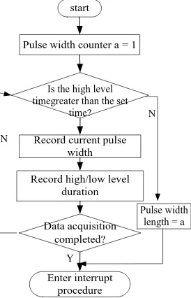
Fuzzy clustering analysis is applied to classify the infrared signal data in the program of remote control transmitting and receiving[6]. Data are collected for the pulse wave transmitted repeatedly by remote controller, the width H of pulse and the information bit expressed by the distance W between pulses, and the threshold value R is calculated by using the information bit when the classification is most reasonable. Because of the limited memory space of the single chip computer, the data are classified and identified. The structure recognition mean compression pulse width counting method is used to compress the collected coded data [7-8]. The position of "0" and "1" combination in statistical pulse width data is the beginning of data for the first time and the end of data for the last time. The encoding data between the beginning of data and the end of data is compressed every 8 bits for one byte, which improves the timeliness and reliability of system data sampling. The pulse data acquisition program is shown in Figure 6. The pulse data compression program is shown in Figure 7.
N Pulse width counter a = 1
Is the high level timegreater than the set
time?
Record current pulse width
Record high/low level duration
Pulse width length = a Data acquisition
completed?
Enter interrupt procedure
start
Y N
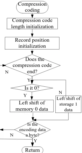
[image:5.595.232.369.513.726.2]Compression coding Compression code length initialization Record position initialization Does the compression code end?
Left shift of memory 0 data
Is it 0?
[image:6.595.233.370.70.325.2]Left shift of storage 1 data Is the encoding data a byte? Return Y N N Y Y N
Figure 7. Data Compression Program.
Result Analysis
Analysis of Signal Waveform Simulation of Infrared Receiving and Transmitting Circuit
Pulse width modulation coding "0" is expressed by pulse width 0.45 ms, period 1.125 ms, interval 0.45 ms, and "1" is expressed by pulse width 0.45 ms, period 0.9 MS and interval 0.9 Ms. The "boot code" and "end code" identified in the storage process, while for instruction coding, only the compression coding between the beginning of data and the end of data is saved, and the compression ratio can reach 17:1, which greatly saves the storage space. The structure recognition mean compression pulse width counting algorithm can greatly reduce the sampling error of pulse wave data in remote control system. In order to ensure the success of UART(Universal Asynchronous Receiver/Transmitter )mode communication in the process of communication, first set the baud rate parameters in the corresponding registers.
The baud rate is determined by the clock factor N:
a BRCLK udrate f N B
(1)
The integer part of the clock factor is placed in the UCBRx register:
( )
UCBRxINT N (2)
The decimal part is placed in the UCBRSx register:
r ( ( )) 8
UCBRSx ound NINT N (3)
The required baud rate in the design process is 9600Hz.
1 104.1667 9600 MHZ N HZ (4)
( ) 104
UCBRxINT N (5)
Setting the same parameters at the transmitter and receiver can read 00011000. The transmitted data is put into the transmitter register UCAxTXBUF, and the corresponding data can be received only by the receiver register UCAxRXBUF. The oscilloscope displays the signal receiving waveform as shown in Figure 8. The simulation of infrared receiving LCD display signal output is shown in Figure 9.
[image:7.595.201.388.288.461.2]Figure 8. Oscilloscope Displays Signal Output Emission Waveform.
Figure 9. Signal Output Simulation of Infrared Receiving LCD Display.
Practical Test of Infrared Remote Control
[image:7.595.190.407.585.717.2]As shown in Figure 10, this paper designs an infrared remote control test device. The right picture is an infrared remote control operation unit, i.e. an electric actuator. The left picture is an information liquid crystal display module, i.e. a 12864 LCD display circuit. The operation test is to electrify the electric actuator, waiting for the successful connection between the wireless communication modules, and using infrared remote control pair. The electric actuator controls and displays the actual valve opening information.
microcontroller is designed. The remote controller achieves the requirements of high speed, low cost and low power consumption. In the process of software coding and decoding of infrared remote control, fuzzy clustering and structure recognition mean compression pulse width counting algorithm are introduced to classify and identify the collected coded data, which solves the problems of errors in the process of data transmission and the complexity of the structure of repeated transmission, compresses the storage space of the system and improves the system. Efficiency and reliability. After testing, the product can operate the electric actuator quickly and conveniently in the factory application and practice, and has certain application value.
Acknowledgment
This work is supported by School of Computer Science and Engineering, North Minzu University (YCX19062).
References
[1] Wu Qiong. Design of Air-conditioning Infrared Remote Controller Based on Single Chip Microcomputer [J]. Electronic World, 2018 (16): 157 + 159.
[2] Jiang Zhiyuan, Zhan Yongqiang. A design scheme of infrared remote controller for universal mobile phone based on front-end server [J]. Cable TV technology, 2017 (11): 98-100.
[3] Li Huijing, Jin Xiaomin, Jingya et al. Signal reception and compression method in intelligent infrared remote controller [J]. Computer engineering and design, 2018, 39 (04): 1006-1010.
[4] Li Huizhen. Research on Interface Interaction Design Based on Big Data Processing Technology [J]. Modern Electronic Technology, 2019, 42(01): 38-41+45.
[5] Zhou Jie, Jiang Zhibin, Zhang Yuanpeng and others. Density-based fuzzy representative point clustering algorithm [J/OL]. Control and decision-making: 1-11 [2019-03-25].
[6] Hao Shaopeng, Zhang Hugo, Hu Jun, Yue Jinghui, Yu Feng, Shen Zhize. Fuzzy Cluster Analysis and Fault Diagnosis of Motor Vibration Signals [J]. Science and Technology and Innovation, 2019 (09): 134-136.
[7] Wu Chengmao, Egret. Robust Fuzzy Clustering Segmentation Algorithms for Adaptive Feature Selection [J]. Minicomputer System, 2018, 39 (08): 1842-1848.