2019 International Conference on Computer Science, Communications and Big Data (CSCBD 2019) ISBN: 978-1-60595-626-8
Design of Dual-band Circularly Polarized Microstrip Antenna
Based on Beidou Application
Mu-yi ZHOU, Yan-zhong YU, Lei JIA and Shi-yu HU
College of Physics & Information Engineering, Quanzhou Normal University, Quanzhou, China
Keywords: Microstrip patch, Double frequency, Circular polarization, Beidou antenna.
Abstract. As satellite navigation technology and industry rapidly progressed, the demand of the navigation antenna is getting a rising increase. The antenna of multi band miniaturized navigation has become a mainstream design. This paper optimized designs a microstrip navigation antenna which works on Beidou B1 (1.561GHz) and B2 (1.207GHz) frequency band. It uses multilayer microstrip patch to achieve dual frequency work of antenna and adopts doubly fed point to realize the circular polarization of the antenna. The simulation results demonstrate that the performance of the designed Beidou antenna meets the requirements of industrial application.
Introduction
With the development of human communication, satellite navigation system has been applied to all aspects of human life. Navigation system is indispensable for communication, positioning and military affairs [1-3]. Beidou Satellite Navigation System is the third mature navigation system developed by our country. It is a global satellite navigation system for providing good positioning and navigation services for all users. Because of the increasing requirements for using, the demand for multi-frequency satellite navigation systems is developing [4-6]. The design of dual-band or multi-band antenna for satellite navigation systems has become a very important issue [7-9]. The design of dual-band will make microstrip antennas more useful in life [10]. In this paper, a dual-frequency circularly polarized microstrip antenna based on Beidou is designed. The special structure of three-layer dielectric slabs, two-layer patches and two feeding points is designed. The center frequencies of the antenna are 1.561 GHz and 1.207 GHz in the B1 and B2 bands of Beidou. Microstrip antenna has many advantages, such as small size, low section, low price and easy to produce. The antenna adopts a cascaded microstrip patch structure. The large patch is below, and the small patch is above. Several resonators are formed, which can act on several different frequency bands to achieve dual-frequency. Wave polarization is divided into linear polarization, elliptical polarization and circular polarization. The antenna designed in this paper is circular polarization, because that linear polarization only points to one direction in the propagation process, while circular polarization electric field can rotate. And circular polarization is relatively more convenient and more in line with the design specifications. In order to achieve circular polarization better, the antenna adopts the mode of dual feed, and then uses the feeding network to output two signals with equal range and their phase error is 90°. Wilkinson power divider is chosen as the feed network, because it has no loss, the input ports match the output ports, good range and phase characteristics, and simple design. The design goals of this paper are Right Hand Circular Polarization (RHCP), return loss < -10dB (S11 < -10 dB), axial ratio < 3 dB and VSWR < 2 dB. By employing the software HFSS, the proposed antenna is molded, analyzed, and optimized. The numerical results are given. The results indicate that antenna designed in the paper can satisfy the requirements of the design.
frequency. The lowermost feed network is directly connected to the uppermost small rectangular patch through the cylinder for feeding. The feed network uses the Wilkinson bisector and the microstrip line feed. The two feed points are separated by 1/4 wavelength to form a 90-degree phase difference. Figure 2 shows the structure of the two-layer antenna patch. The patch on the top is smaller than the patch below, and the sizes of the two are different. The sizes of the proposed antenna are listed in Table 1, which are obtained by repeated optimization simulation.
[image:2.595.411.498.155.292.2]
Figure 1. Model of the proposed antenna. Figure 2. Structure of the two-layer antenna patch.
Table 1. Optimal sizes of the proposed antenna.
Parameters W W2 L L1
Values (mm) 73 88 73 88
Simulation Results
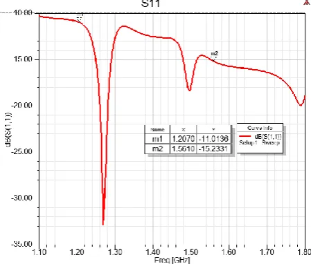
The proposed antenna is modeled and analyzed by HFSS. Repeated parameter scanning and optimization requires the best size. The return loss as functions of frequency for the proposed antenna is shown in Figure 3. It can be seen from Figure 3 that S11 < -10 dB over the entire frequency range of the Beidou B1 and B2. It is -11.0136 dB at the frequency of 1.207 GHz and -15.2331 dB at the frequency of 1.561 GHz. Meets the original design goals.
[image:2.595.188.413.529.720.2]The VSWR of the antenna, as shown in Figure 4, can be seen that VSWR is less than 2dB in both frequency bands. It can be seen from the points marked in the Figure 4 that it is 1.7832 in the 1.207GHz band and 1.4187 in the 1.561 GHz band. Both frequency bands are between 1 and 2, meeting the design requirements.
Figure 4. VSWR as function of frequency for the proposed antenna.
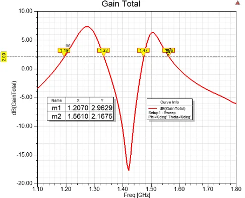
[image:3.595.187.413.362.553.2]The simulation results of the axial ratio are shown in Figure 5, and both Beidou frequency bands are less than 3dB, which is in line with the antenna index. Specifically, it is 2.8724dB at 1.207GHz and 1.2242dB at 1.561GHz, both of which are less than 3dB, which meets the requirements. Figure 6 below shows the total gain curve of the antenna. The total gain of both bands is designed to be > 2dB.
[image:3.595.177.420.579.776.2]Figure 7(a) and Figure 8(a) below show the antenna high-band and low-band gain diagrams. According to the figure, the direction of the total gain and the right hand circular polarized gain are basically similar, so this design completes the requirements of the right hand circularly polarization. The specific high frequency is 2.1824dB at 1.5605GHz, and the low frequency is 3.1602dB at 1.2095GHz. Figure 7(b) and Figure 8(b) show the 3D gain plots for the high and low bands.
(a) 2D gain (b) 3D gain
Figure 7. 2D gain and 3D gain at 1.561GHz.
[image:4.595.73.511.87.561.2]
(a) 2D gain (b) 3D gain
Figure 8. 2D gain and 3D gain at 1.207 GHz.
Conclusion
The dual-band circularly polarized microstrip antenna is designed and analyzed by HFSS. The simulation results show that the designed antenna has basically reached the design goal of this paper: it can work in two different frequency bands of Beidou, with S11 < -10 dB, VSWR < 2 dB, and axial ratio < 3 dB. Although it was not achieved further optimizations in antenna’s size, we have hoped to achieve breakthroughs in this area in the future and achieve better goals.
Acknowledgements
References
[1] N. Zhu, P. Jin, R. W. Ziolkowski, H. Xin. Design of a GPS L1 rectenna by using a metamaterial-inspired eclectically small antenna, 2011.
[2] S. L. Ma, J. S. Row. Design of single-feed dual-frequency patch antenna for GPS and WLAN applications, IEEE Transactions on Antennas and Propagation, 2011 (59), 3433-3436.
[3] S. A Rezaeieh. Dual band dual sense circularly polarised monopole antenna for GPS and WLAN applications, Electronics Letters, 2011 (22), 1212.
[4] W. T. Hsieh, T. H. Chang, J. F. Kiang. Dual-band circularly polarized cavity-backed annular slot antenna for GPS receiver, IEEE Transactions on Antennas and Propagation, 2012 (60), 2076-2080.
[5] X. Y. Sun, Z. J. Zhang, Z. H. Feng. Dual-band circularly polarized stacked annular-ring patch antenna for GPS application, IEEE Antennas and Wireless Propagation Letters, 2011 (10) 49-52.
[6] K.V. S. Rao, P. V. Nikitin, S. F. Lam. Antenna design for UHF RFID tags: a review and a practical application, IEEE Trans Antennas Propag. 2005 (53), 3870-3876.
[7] N. Zhu, R. W. Ziolkowski. Metamaterial-inspired, near-field resonant parasitic GPS antennas: Designs and experiments, 2011 IEEE International Symposium on Antennas & Propagation, 2011.
[8] K. Lee, Y. Jee. Multiresonance coplanar waveguide-fed monopole antennas with meander strips for GSM/GPS/PCS/DCS/WCDMA applications, Microwave & Optical Technology Letters, 2011 (53). 2438-2441.
[9] F. Canneva, F. Ferrero, J. Ribero, R. M. Staraj. New reconfigurable small antenna for DVB-H and GPS standard, IEEE International Symposium on Antennas & Propagation, 2011.