http://dx.doi.org/10.4236/jss.2015.37010
An IoT Multi-Interface Gateway for Building
a Smart Space
Chao-Tsun Chang1, Chih-Yung Chang2*, Ramon Dario Borja Martinez2, Po-Ting Chen2, Yen-Da Chen3
1Department of Information Management, Hsiuping University of Science and Technology, Taichung,
Chinese Taipei
2Department of Computer Science and Information Engineering, Tamkang University, New Taipei City,
Chinese Taipei
3Department of Computer Information and Network Engineering, Lunghwa University of Science and
Technology, Taoyuan, Chinese Taipei Email: [email protected]
Received 22 May 2015; accepted 11 July 2015; published 14 July 2015
Abstract
Connecting smart objects in a wireless manner can establish an Internet of Things (IoT) smart space. However, a variety of wireless technologies have been embedded into smart objects that they cannot exchange information since they apply different standards. To provide information exchange in heterogeneous networks, this paper designs an IoT multi-interface gateway, which can be used in some smart spaces to automatically control traditional TV, air condition, smart meter, sphygmomanometer, smart phone, etc.
Keywords
Gateway, Heterogeneous Network, Internet of Things (IoT), Smart Object, Smart Space
1. Introduction
In recent years, Internet of Things (IoT) technology has attracted many attentions, making the unidentifiable ob-jects into identifiable, recognized, interconnected intelligent obob-jects. The development of IoT can support a va-riety of applications, including Intelligent Power Grid [1] [2], Intelligent Transportation [3] [4], Intelligent Medi-cine and Healthcare [5] [6], Intelligent Art [7] [8], Intelligent Logistics [9] [10], Intelligent Environmental Mon-itoring [11] [12] [13], Smart Life [14] [15], etc. However, their heterogeneous systems can only be utilized by using specific network packet conversion, which cannot be integrated with general heterogeneous network com-munication standards, such as Bluetooth, ZigBee, Infrared, etc. Therefore, the integration within the heteroge-neous network is critical.
To solve the heterogeneous network transmission problems, this paper aims to design and implement a hete-rogeneous gateway which plays the role of translator of different wireless communication protocols. The de-signed heterogeneous gateway is able to communicate with a variety of smart objects using Wi-Fi, ZigBee, Blu-etooth and IrDA standards. As a result, all objects can exchange information through the designed gateway.
1) The designed IoT gateway bridges the lower layer (perceive layer) and network layer of the IoT.
2) The designed IoT gateway enables the communication among different interfaces, including Wi-Fi, ZigBee, Bluetooth and 3G, which are general used by the smart objects in the IoT applications.
3) The gateway provides solution to the interference arisen from the coexistence of different protocols using the same ISM band.
The remaining part of this paper is organized as follows. Section 2 presents the system architecture of the de-signed IoT gateway. Sections 3 and 4 present the design of the hardware/Firmware components of the proposed gateway. Finally, the conclusions are drawn in Section 5.
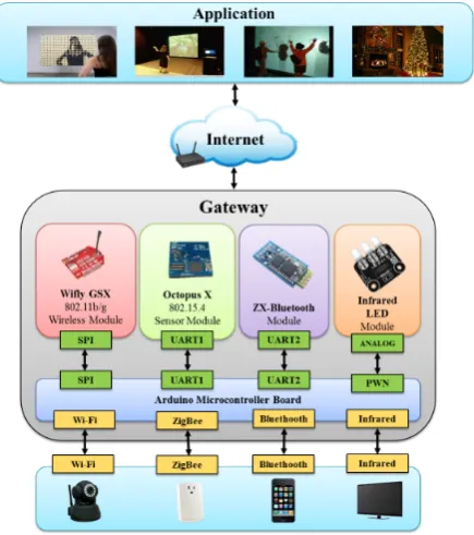
2. System Architecture of an IoT Gateway
To integrate various devices with wireless communication protocols and communicate between heterogeneous networks, an Arduino microcontroller board, Octopus X wireless sensing module, ZX-Bluetooth chip module, WiFly GSX 802.11b/g wireless network chip module, and IR light-emitting diode (LED) transmitting module were employed to form a heterogeneous network gateway capable of supporting heterogeneous communications. Detailed descriptions of these hardware modules and their architectures are provided below.
The logic architecture of a heterogeneous network gateway is shown in Figure 1. Both the Octopus X wire-less sensing module and the ZX-Bluetooth chip module use the universal asynchronous receiver/transmitter (UART) communication interface to connect to the Arduino microcontroller board. The IR transmission module is connected to the pulse width modulation pins on the Arduino microcontroller board and simulates IR analog signals by using the digital pins.
3. Hardware Implementation and Integration
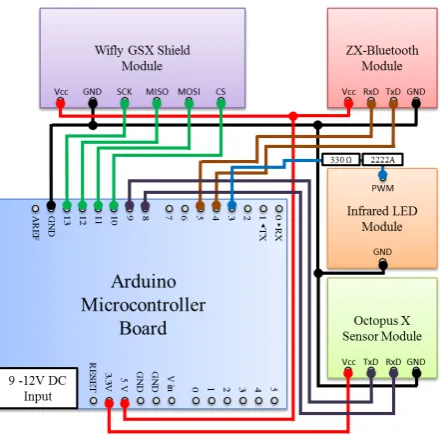
This section presents the hardware implementation of the heterogeneous network gateways. The integrated physical structure of the heterogeneous network gateway is shown in Figure 2.
[image:2.595.206.424.450.696.2]The pins of each wireless communication module are connected to the pins of the Arduino microcontroller board. Figure 3 shows a circuit diagram of the heterogeneous network gateway. In this figure, the TxD and RxD pins of the ZX-Bluetooth chip module are connected to the fourth and fifth pins on the Arduino microcontroller board. By contrast, the TxD and RxD pins of the Octopus X wireless sensing module are connected to the eighth and ninth pins on the Arduino microcontroller board, respectively.
Figure 2. Physical structure of a heterogeneous network ga-teway.
Figure 3.Heterogeneous network gateway circuit diagram.
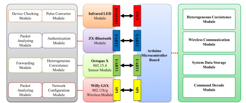
4. Firmware Platform for Heterogeneous Network Gateway
The section presents the functions and corresponding firmware operations of the designed gateway. Figure 4 depicts the firmware modules of the heterogeneous network gateway.
The wireless communication module comprises the WiFly GSX, Octopus X, ZX-Bluetooth, and IR transfer modules.In the WiFly GSX wireless network chip module, the firmware functions comprise four modules, that is, the network configuration module, packet analyzing module, serial converter module, and transmission mod-ule. The function of the network configuration module is to configure the service set identifier (SSID) and fre-quency band of the wireless network to allow other embedded devices with wireless network functions to con-nect using the identification code. The function of the packet-analyzing module is to decrypt and analyze the data packets. The function of the serial converter module is to convert packets among different communication interfaces. The function of the transmission module is to transmit and receive data packets. Regarding the firm-ware system, embedded devices can be connected to the WiFly GSX module by using the SSID identification code configured through the network configuration module. When the connection of devices is complete, data packets are sent through the transmission module to the packet analyzing module for decryption and analysis. Then, using the serial converter module, analyzed data or control commands are sent to the Arduino microcon-troller board for further processing.
[image:3.595.203.424.242.460.2]Figure 4.Firmware architectural of the designed heterogeneous network gateway.
functions of the transmission module comprise the transmission and reception of external data and communica-tion with the Arduino microcontroller board. The packet analyzing module is used to decrypt and analyze data packets. In the firmware system, when a pair of Bluetooth devices is connected, the authentication module is used for device pairing and password authentication. After authentication, data packets are received by the transmission module and transferred to the packet analyzing module to resolve data packets. Finally, the packets are returned to the transmission module and transferred to the Arduino microcontroller board through the UART communication interface.
In the Octopus X wireless sensing module, the firmware functions involve the following four modules: the node information module, identification module, debugging module, and forwarding module. The node informa-tion module exchanges module informainforma-tion using ZigBee protocols. The identificainforma-tion module is primarily re-sponsible for providing embedded devices with a unique serial number that distinguishes every device. The de-bugging module is primarily employed for controlling the LED module on the Octopus X module to facilitate testing and debugging. The forwarding module is responsible for transferring collected data or commands to other devices through the UART communication interface between the Arduino microcontroller board and the Octopus X module. In the firmware system process, the Octopus X module collects current information from neighboring nodes by using the node information module to establish a star network. Then, the Octopus X mod-ule assigns a set of unique serial numbers to all embedded devices in the star network. When the Octopus X module receives a set of control commands from the Arduino microcontroller board, command packets are trans-mitted to the embedded device indicated in the network command through the forwarding module to control the device.
Regarding the IR transfer module, the firmware function involves three modules, namely, a pulse transmis-sion module, pulse converter module, and device checking module. The pulse transmistransmis-sion module is responsi-ble for receiving or sending IR pulse signals. The pulse converter module is used for converting the IR pulse and digital PWM signals. The device checking module resolves the IR code of each device and adjusts the transfer pulse formats according to the device codes. During the firmware system process, external IR signals can be re-ceived through the pulse transmission module and transformed into digital PWM signals resolvable in the Ar-duino microcontroller board by using the pulse converter module. After processing using the ArAr-duino microcon-troller board, signals are returned to the device checking module to adjust the pulse format of the devices. Final-ly, the IR pulse signals are then transmitted to the device through the pulse transmission module.
5. Conclusion
Wi-Fi wireless network chip module, Bluetooth chip module, and the IR LED transfer module. The resulting heterogeneous network gateway could be used as a coordinator capable of integrating various communication protocols. In addition to the hardware design, the firmware programming was also developed according to the characteristics of each hardware module, enabling the wireless multi-interface to cooperatively work. The estab-lishment of self-defined packet format involved defining the packet fields and formats, which provided the ga-teway with functions of reducing errors produced during data and controlled command transfer among devices.
Acknowledgements
This work was supported by the Ministry of Science and Technology of the Republic of China under Contract MOST 103-2221-E-164-006.
References
[1] He, M., Murugesan, S. and Zhang, J. (2011) Multiple Timescale Dispatch and Scheduling for Stochastic Reliability in Smart Grids with Wind Generation Integration. IEEE International Conference on Computer Communications, Shanghai, China, 461-465. http://dx.doi.org/10.1109/infcom.2011.5935204
[2] Varaiya, P.P., Wu, F.F. and Bialek, J.W. (2011) Smart Operation of Smart Grid: Risk-Limiting Dispatch. IEEE Journal of Proceedings, 99, 40-57. http://dx.doi.org/10.1109/JPROC.2010.2080250
[3] Qu, F., Wang, F.Y. and Yang, L. (2010) Intelligent Transportation Spaces: Vehicles, Traffic, Communications, and Beyond. IEEE Communications Magazine, 48, 136-142. http://dx.doi.org/10.1109/MCOM.2010.5621980
[4] Eisenman, S.B., Miluzzo, E., Lane, N.D., Peterson, R.A., Ahn, G.S. and Campbell, A.T. (2009) BikeNet: A Mobile Sensing System for Cyclist Experience Mapping. ACM Transactions on Sensor Networks, 6, Article 6.
[5] L´opez, G., Custodio, V. and Moreno, J.I. (2010) LOBIN: E-Textile and Wireless-Sensor-Network-Based Platform for Healthcare Monitoring in Future Hospital Environments. IEEE Transactions on Information Technology in Biomedi-cine, 14, 1446-1458. http://dx.doi.org/10.1109/TITB.2010.2058812
[6] Otal, B., Alonso, L. and Verikoukis, C. (2009) Highly Reliable Energy-Saving MAC for Wireless Body Sensor Net-works in Healthcare Systems. IEEE Journal on Selected Areas in Communications, 27, 553-565.
http://dx.doi.org/10.1109/JSAC.2009.090516
[7] Streitz, N.A., Röcker, C., Prante, T., van Alphen, D., Stenzel, R. and Magerkurth, C. (2005) Designing Smart Artifacts for Smart Environments. Computer, 38, 41-49. http://dx.doi.org/10.1109/MC.2005.92
[8] Ning, Y. and Sim, T. (2008) Interactive Portrait Art. IEEE Workshop on Application of Computer Vision, Frisco, Col-orado, USA, January. http://dx.doi.org/10.1109/wacv.2008.4543998
[9] Karkkainen, M. (2003) Increasing Efficiency in the Supply Chain for Short Shelf Life Goods Using RFID Tagging.
International Journal of Retail and Distribution Management, 31, 529-536.
http://dx.doi.org/10.1108/09590550310497058
[10] Qiu, R.G. (2007) RFID-Enabled Automation in Support of Factory Integration. Robotics and Computer-Integrated Manufacturing, 23, 677-683. http://dx.doi.org/10.1016/j.rcim.2007.02.002
[11] Buragohain, C., Agrawal, D. and Suri, S. (2006) Distributed Navigation Algorithm for Sensor Networks. IEEE Inter-national Conference on Computer Communications, Barcelona, Spain, April.
http://dx.doi.org/10.1109/infocom.2006.191
[12] Li, M., Liu, Y., Wang, J. and Yang, Z. (2009) Sensor Network Navigation without Locations. IEEE International Conference on Computer Communications, Rio de Janeiro, April, 2419-2427.
http://dx.doi.org/10.1109/infcom.2009.5062169
[13] Mohan, P., Padmanabhan, V.N. and Ramjee, R. (2008) Nericell: Rich Monitoring of Road and Traffic Conditions Us-ing Mobile Smartphones. Proceedings of the 6th ACM Conference on Embedded Network Sensor Systems, New York, USA, November, 323-336.
[14] Han, D-M. and Lim, J-H. (2010) Design and Implementation of Smart Home Energy Management Systems Based on ZigBee. IEEE Transactions on Consumer Electronics, 56, 1417-1425. http://dx.doi.org/10.1109/TCE.2010.5606278
[15] Byun, J. and Park, S. (2011) Development of a Self-Adapting Intelligent System for Building Energy Saving and Con-text-Aware Smart Services. IEEE Transactions on Consumer Electronics, 57, 90-98.