Degradation Measures in Free Space Optical
Communication (FSO) and it’s Mitigation
Techniques - A Review
Vishal Sharma
Shaheed Bhagat Singh State Technical Campus Ferozepur, Punjab,India
Gurimandeep Kaur
Shaheed Bhagat Singh State Technical Campus Ferozepur, Punjab, India
ABSTRACT
Unlike radio and microwave systems, Free Space Optics (FSO) is an optical technology which requires no spectrum licensing or frequency coordination with other users and provides secure transmission because of negligible interception by using point-to-point laser signals in conjunction with low errors than that of optical fiber transmission. This paper is an endeavor to thrash out about internal and external parameters that degrade the performance of FSO systems in conjunction with the alleviation techniques to realize a high speed, bandwidth efficient long haul FSO transmission system.
General Terms
Power loss, FSO linkKeywords
FSO systems, Attenuation, Diversity techniques
1.
INTRODUCTION
The remarkable growth of internet and other wireless networks had a huge influence in the modern era of telecommunication. Being in the era of ever-present connectivity, the requirement of high speed networks had put the pressure on wireless communication networks to increase both the transmission capacity and the coverage area. The recent trends for ultramodern broadband, interactive and multimedia services over wireless media in both mobile and fixed cellular networks are to reduce cell size to accommodate more users together with to operate in the millimeter wave (mm-wave) frequency bands to avoid spectral congestion in the lower frequency bands [1]. High capacity, low power consumption, light weight, small sizes, high data rates and low costs for satellite cross-links are other promises of FSO technology. It is a significant building block for wide area space networks, supporting mobile users, high speed data services for small satellite terminals and serving as a backbone network for high speed trunking [2]. However, FSO is exceptionally expensive preventing it from replacing the current wireless networks. Improvement of physical-link communication efficiency by an order of magnitude using photon-counting receivers for vacuum channels and by reducing the system complexity, weight, and power for space systems helps in reducing the cost. By incorporating of coherent systems in links and in multiple access applications where coherent processing can reduce the level of interference, a significant reduction in system-cost can be realized [3].
FSO technology i s i mplement ed using a l aser devi ce whi ch can be mounted on rooftops, corners of
buildings or even inside offices. FSO devices look like security video cameras and basically consist of an optical transceiver with a laser transmitter and receiver to provide full duplex capability. FSO unit using a high-power optical source also has a lens that transmits light through the atmosphere to other lens receiving information. If the transmitter source does not produce a sufficiently parallel beam to travel the required distance, the collimation can be done with lens. The receiving lens further connects to a high-sensitivity receiver via optical fiber. The architecture of FSO system can be point to point, mesh or point to multipoint. Low-power infrared beams, which does not harm the eyes, is the other mean by which FSO systems can transmit data through the air between transceivers, or link heads over distances of several hundred meters to a few kilometers, depending upon atmospheric conditions [4].
No doubt, FSO systems can be a good way out for some broadband networks requirements due to many advantages but there are some restrictions that limit its performance. So, it is important to take several FSO system parameters into consideration such as internal- and external-parameters. Most significant external-parameters are rain, dust, snow, fog, or smog that deteriorate the transmission path and shut down the network. These environmental changes are inevitable and must be considered while designing a FSO system. The internal parameters are related to optical power, transmission bandwidth, divergence angle, optical loss on transmitter side, BER, lens diameter and receiver field-of-view (FOV) [5]. This paper is an enterprise to analyze a high speed, bandwidth efficient long haul FSO transmission system by considering all the degrading parameters in different atmospheric conditions in conjunction with the mitigation techniques reported in previous research work.
2.
DEGRADING FACTORS IN FSO AND
ITS MITIGATION TECHNIQUES
Selective scattering occurs when certain particles are more effective at scattering of a particular wavelength of light. Air molecules, like oxygen and nitrogen for example, are small in size and thus more effective at scattering of shorter wavelengths of light. Mie Scattering occurs when scatterer size is comparable to wavelength. When the scatterer size is much larger than the wavelength of light, it is non-selective scattering. Light signals transmitted through clouds will interact with the cloud particles in the transmission path. Photon–particle interaction causes dispersion of light signals, which has significant effects on signal attenuation or scattering. The correlation between spatial and angular dispersion plays an important role on the receiver design [7]. FSO products which have widely spaced redundant transmitters and large receive optics eliminate interference concerns from objects such as birds. On a typical day, an object covering 98% of the receive aperture and all but 1 transmitter; will not cause a FSO link to drop out. Thus, birds are unlikely to have any impact on FSO transmission. Scintillation occurs because of atmospheric turbulence that produces many temporary areas named as Fresnel zone. Atmospheric turbulence produces temporary pockets of air with different temperatures, different densities, and hence, will produce different refractive index. As the turbulence is random, these pockets are continuously being created and destroyed [8]. This scintillation effects on FSO can be tackled by multi beam approach exploiting multiple regions of space, this approach is called spatial diversity. Fog substantially attenuates the visible radiations and it has a similar affect on the near-infrared wavelengths that are employed in FSO systems.
Fog hinders the passage of light by absorption, scattering and reflection. Dealing with fog- which is known as Mie scattering, is largely a matter of boosting the transmitted power. The only weather that could affect the transmission of a hybrid FSO/RF is the conditions of simultaneous heavy rain and thick fog but these conditions would not occur simultaneously, because as the rain falls, the rain droplets would absorb the suspended fog water droplets, thus diminishing the fog. Rain drop can vary in size from 0.1 mm to 10 mm and fog from 1 to 20 microns [9]. Hybrid networks consisting of FSO link and back up link in the GHz frequency range renders high availability besides providing comparable data rate but the backup link should be nearly immune to weather attenuation for achieving good availability and reliability of the link [9-10]. For back up, an intelligent switch-over between two links is required depending upon the atmospheric attenuations. The forward prediction of the received signal strength is one of the remedy used to improve the performance of such hybrid networks [11-12]. However, different optical wavelengths suffer different attenuation but the use of longer wavelengths having high penetration against fog, can overcome the scattering or absorption of data [13-15].
Hence, the optical signal that passes through the atmosphere between the FSO links gets randomly attenuated up to few hundreds of dB/km by fog and rain. With the increase of size of water droplet, the refraction and reflection process occurs due to combined effect of many water droplets in the atmosphere, resulting in multiple scattering [16]. The
[17]. The attenuation due to rain in connection with the visibility range can be calculated by [18] as
V rain
9 . 2
; Where, V is visibility range.
There is another law, named as Beers-Lambert Law, which also evaluates the optical power loss of the optical signal through atmosphere [19]. According to this law, the attenuation of the optical signal is associated with the distribution of drop size, shape and temperature of rain drops. The relationship between specific attenuation and rain rate is computed as
R kR. Where, k and α depend upon the frequency and microstructure of rain [19-23] and are mentioned in Crane model for various frequencies. The rain attenuation from 1 to 1000 GHz was calculated by using both log-normal and weibull distributions for raindrop size [24]. The temperature, another important factor, generally, used in the range of 0o to 20o C in terrestrial links [25-26], does not significantly affect the FSO link above 15 GHz. The another imperative performance parameter of such systems i.e. link margin, depends upon receiver sensitivity, link geometrical attenuation, atmospheric attenuation, other system dependent losses [27], which, further, is a function of optical beam between transmitter and receiver. The beam divergence is mathematically expressed as) ( log 10 )
( 10
c d geo
S S dB
A
Where, Sc is capture surface area of received beam, Sd is the
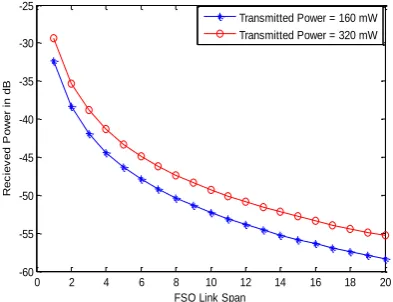
surface area of transmit beam at range d. This shows the attenuation of signal in FSO link significantly depends upon visibility range and atmospheric conditions. The International visibility for weather conditions and precipitation for rain conditions [28] are depicted in Table 1. The signal attenuation based on the visibility range estimation is computed by employing Kim’s model. The exponential Beers-Lambert Law gives the attenuation of laser power through atmosphere as [29-30] and demonstrated the dependence of atmospheric attenuation upon a number of parameters such as visibility, size distribution of the scattering particles, bit rate, FSO link span, optical transmission power, operating wavelength, antenna’s aperture. According to KIM model, the received power under different weather conditions have been calculated at different transmitted power and at varied values of antenna’s apertures as depicted in Fig. 1-2.The bit rate is taken as 1 Gbps and transmitted over FSO link at operating wavelength of 1550nm. The transmitter’s and receiver’s efficiency is kept at 0.8 and 0.75 respectively.
Table 1. International visibility for weather conditions and precipitation for rain conditions
Weather
condition Precipitation
Amount (mm/hr)
Visibility (V)
Light fog Cloud and
Heavy Rain 100 770m - 1 km
Thin fog Heavy Rain 25 2 km
Haze Medium Rain 12.5 2.8 km - 4 km Light
[image:3.595.55.281.95.405.2]Haze Light Rain 2.5 5.9 km - 10 km Clear Drizzle 0.25 18 km - 20 km
[image:3.595.324.524.297.455.2]Fig 1: Evaluation of Received power (dB) with different transmitted power with aperture 10 cm at 1550 nm
Fig 2: Evaluation of Received power (dB) with different transmitted power with aperture 15 cm at 1550nm
Fig 3: Evaluation of Attenuation (dB) at different wavelengths under high visibility conditions with
[image:3.595.65.262.452.603.2]transmitter power of 320 mW
Fig 4: Evaluation of Attenuation (dB) at different wavelengths under dense fog visibility with transmitter
power of 320 mW
Fig 5: Evaluation of Attenuation (dB) at different wavelengths under average visibility condition with
transmitter power of 320 mW
0 2 4 6 8 10 12 14 16 18 20
-65 -60 -55 -50 -45 -40 -35
FSO Link Span
R
e
c
ie
v
e
d
P
o
w
e
r
in
d
B
Transmitted Power = 160mW Transmitted Power = 320mW
0 2 4 6 8 10 12 14 16 18 20
-60 -55 -50 -45 -40 -35 -30 -25
FSO Link Span
R
e
c
ie
v
e
d
P
o
w
e
r
in
d
B
Transmitted Power = 160 mW Transmitted Power = 320 mW
0 100 200 300 400 500 600 700 800 900 1000 0
0.005 0.01 0.015 0.02 0.025 0.03 0.035 0.04
FSO Link Span in meters
A
tt
e
n
u
a
ti
o
n
i
n
d
B
1550 nm 850 nm 950 nm
0 100 200 300 400 500 600 700 800 900 1000 0
0.01 0.02 0.03 0.04 0.05 0.06 0.07 0.08
FSO Link in meters
A
tt
e
n
u
a
ti
o
n
i
n
d
B
1550 nm 850 nm 950 nm
0 100 200 300 400 500 600 700 800 900 1000 0
0.005 0.01 0.015 0.02 0.025 0.03 0.035 0.04 0.045
FSO Link Span in meters
A
tt
e
n
u
a
ti
o
n
i
n
d
B
[image:3.595.324.524.511.667.2]To improve efficiency of FSO links, the diversity combining techniques can be applied to a synchronous laser communication system through the turbulent atmosphere [31]. In this scheme, a single information bearing signal is transmitted over statistically independent fading channels, and the multiple replicas are combined at the receiver. In maximal ratio combining (MRC) diversity technique, the receiver co-phases the intermediate signals, adjusts their amplitude separately, and sums them to obtain a composite signal with improvement in SNR. But in case of selective combining diversity technique, a selection receiver is quite different from the coherent MRC summing receiver as the single strongest intermediate signal is switched to the output, while all the other array element signals are discarded. This technique improves mean SNR value of collected signal and also provides reduction in signal fading [32]. In other diversity technique, coherent fiber arrays consisting of densely packed multiple sub-apertures interfaced with single mode fiber are used in which the output of SSMF fiber is detected and the photocurrents are adaptively co-phased and scaled. Subsequently, these well-scaled photocurrents are summed to mitigate the signal fading associated with atmospheric turbulence. This technique also helps in compensating for the imperfect fiber coupling efficiency [33]. In diversity combining techniques, signals detected by two or more apertures are combined to reduce the channels of deep fades and improve detection efficiency [32, 34].
3.
CONCLUSION
By analyzing different degrading factors and its mitigation schemes in FSO technology, it is concluded that the rain drop, fog and rain drop size plays an important role in attenuating the power loss of FSO link. It has been observed that by proper selection of visibility, size distribution of the scattering particles, bit rate, optical transmission power, operating wavelength and antenna’s aperture, the FSO link can be optimized with acceptable attenuation. Turbulence also plays an important role in attenuating the power loss of FSO link. By pre-determining the turbulence induced scintillation and correlation length of intensity fluctuations, the MLSD and PSAD schemes proves to be very helpful in reducing the atmospheric attenuation. Diversity combining techniques proves to be a high-quality driving force to minimize the effect of turbulence and to realize a high speed, bandwidth efficient long haul FSO transmission system.
4.
REFERENCES
[1] Zin, A.M, Bongsu, M.S, Idrus. S.M, Zulkifl, N., “An overview of radio-over-fiber network technology”, IEEE International Conference on Photonics (ICP), pp: 1-3, 2010.
[2] Chan, V.W.S., “Optical space communications: a key
building block for wide area space networks”, Lasers and Electro-Optics Society, volume 1,pp: 41-42, 1999.
[3] Chan, V.W.S., “Free-Space Optical Communications”,
Journal of Lightwave Technology, volume 24, Issue 12, pp: 4750-4762, 2006.
[4] Willebrand, H.A., Ghuman, B.S., “Fiber optics without
fiber”, Spectrum, IEEE, volume 38, Issue 8, pp: 40-45, 2001.
[6] Zhuanhong Jia, Qinglin Zhu, Faliang Ao, “Atmospheric Attenuation Analysis in the FSO Link”, International technology on Communication Technology (ICCT), pp: 1- 4, 2006.
[7] Binbin Wu, Zeinab Hajjarian and Mohsen Kavehrad, “Free space optical communications through clouds: analysis of signal characteristics”, Applied Optics, volume 47, Issue 17, pp: 3168-3176, 2008.
[8] Ananda Ekaputera Sidarta, “Free Space Optics (FSO) Links in Singapore: Scintillation Effects”, 9th National Undergraduate Research Opportunities Programme Congress 2003, Nanyang Technological University, Singapore.
[9] Gurdeep Singh, Tanvir Singh, Vinaykant, Vasishath Kaushal, “Free Space Optics: Atmospheric Effects & Back Up”, International Journal of Research in Computer Science, volume 1, Issue 1, pp: 25-30, 2011.
[10]Nadeem, F., Leitgeb E., Koudelka, O., Javornic, T., Kandus, G., “Comparing the rain effects on hybrid network using optical wireless and GHz links”, 4th IEEE International Conference on Emerging Technologies (ICET), pp: 156-161, 2008.
[11]Nadeem, F., Leitgeb, E., Kvicera, V.,Grabner, M.,Awan, M.S.,Kandus, G., “Simulation and analysis of
FSO/RF switch over for different atmospheric effects”,
10th IEEE International Conference on Telecommunications (ConTEL), pp: 39-43, 2009. [12]Nadeem, F., Leitgeb, E., Awan, M.S., Kandus, G.,
“Forward prediction of FSO received signal for FSO/RF hybrid network”, International Workshop onSatellite and Space Communications (IWSSC), pp: 196-200, 2009. [13]Nadeem, F., Leitgeb, E., Awan, M.S.,Kandus,
G., “Optical wavelengths comparison for different
weather conditions”, International Workshop onSatellite and Space Communications (IWSSC), pp: 279-283, 2009.
[14]Nadeem, F., Leitgeb, E., Awan, M.S.,Loeschnig, M., Kandus, G., “Comparison of FSO 10 Micrometer
Availability with FSO 850 nm/RF Hybrid Network Availability”, IEEE, 70th Vehicular Technology
Conference Fall (VCT-Fall),pp: 1-4, 2009.
[15]Nadeem, F., Leitgeb, E., Awan, M.S., Kandus, G., “FSO/RF Hybrid Network Availability Analysis
Under Different Weather Condition” 3rd International Conference on Next Generation Mobile Applications, Services and Technologies (NGMAST), pp: 239-244, 2009.
[16]T.H. Carbonneau, D.R. Wisley, “Opportunities and Challenges for optical wireless; the competitive advantage of free space telecommunications links in today’s crowded market place”, SPIE Conference on Optical Wireless Communications, Masachusetts, volume 3232, Issue 119, 1998.
[17]H.C Van de Hulst, “Light scattering by small particles”, Dover publication, New York, 1981.
[19]F. Nadeem, E. Leitgeb, O. Koudelka, “Comparing the rain effects on hybrid network using optical wireless and GHz links”, 4th International Conference on Emerging Technologies (ICET), pp: 156-161, 2008.
[20]ITU-R, P.838-1: Specific Attenuation Model for Rain for use in Prediction Methods.
[21]R.K. Crane, “Prediction of Attenuation by Rain”, IEEE Transactions on Communications, volume 28, Issue 9, pp: 1717-1733, 1980.
[22]R.K. Crane, “A Two Component Rain Model for the Prediction of Attenuation Statistics”, Journal of Radio Science, volume 20, pp: 1371-1382, 1982.
[23]G.Brussaard, P.A. Watson, “Atmospheric Modelling and Millimetre Wave Propagation”, Springer publication, ISBN: 978-0-412-56230-3, 1994.
[24]Sekine, M., Chii-Dong Chen,Musha, T., “Rain attenuation from log-normal and Weibull raindrop-size distributions”, IEEE Transactions on Antennas and Propagation, volume 35, Issue 3, pp: 358-359, 1987. [25]E. Damosso, G. de Renzis, F. Fedi and P. Migliorini “A
systematic comparison of rain attenuation prediction methods of terrestrial paths", Paper presented at URSI open symposium on effects of lower atmosphere on radio frequencies above 1 GHz, Lennoxville, Que. volume 35,
pp: 463-469, 1980.
[26]Upton, S.A.J., Evans, B.G., Holt, A.R., “Effects of drop
size and temperature on forward and backward scattering of microwaves by raindrops”, IET Journals and Magazines on Electronics Letters, volume 15, Issue 23, pp: 760-762, 1979.
[27] Haim Manor and Sholmi Arnon, “Performance of an optical wireless communication system as a function of
wavelength”, Journal of Applied Optics, Issue 21, volume 42, 2003.
[28] Prediction methods required for the design of terrestrial free-space optical links, ITU-R Recommendation P.1814, 2007.
[29]Isaae I. Kim, Bruce McArthur and Eric Korevaar, “Comparison of laser beam propagation at 785 nm and 1550 nm in fog and haze for optical wireless communications”, Proc. SPIE, volume 4214, pp: 26-37, 2001.
[30]Awan, M.S., Leitgeb, E., Marzuki, Khan, M.S., Nadeem, F., Capsoni, C., “Evaluation of fog attenuation results for optical wireless links in free space”, International workshop on Satellite and Space Communications (IWSSC), IEEE, pp: 112-114, 2008.
[31]A. Belmonte and J. M. Kahn, “Analysis of a Field-Conjugation Adaptive Arrary for Coherent Free-Space Optical Links”, Proceedings of OSA Topical Meeting on applications of Lasers for Sensing and Free Space Communications, 2010.
[32]A. Belmonte and J. M. Kahn, “Capacity of Coherent Free-Space Optical Links using Diversity Combining techniques”, Journal of Optics Express, volume 17, Issue 15, pp: 12601-12611, 2009.
[33]A. Belmonte and J. M. Kahn, “Field Conjugation Adaptive Arrays in Free-Space Coherent Laser Communications”, Journal of Optical Communication Network, volume 3, Issue 11, pp: 830-838, 2011. [34]E. J. Lee and V. W. Chan, “Diversity coherent and