~) ~3 ~
Field Engineering
®Maintenance Manual
Maior Revision, November 1964
This manual, Form 225-6493-4, supersedes and obsoletes both the previous edition, 225-6493-3; and Form 225-3282-0.
The information in both those publications is consolidated, reorganized, and updated to the latest engineering levels.
Np\lIT infnrmlltinn inl'ln(lps nrncpdllres for: new style ribbon-shi~id 're~i~~;;~~t: h-yd;~~iic'" unit oil-seal replaceme~t, Model 3 train cartridge gear replacement, and accumulative slug-to-slug clearance adjustment, as well as a regrouping of related adjust-ments under Print Quality Adjusttnents.
New information is included for the Model 6, and some Figures are added to support the text where necessary.
Address comments concerning the content of this publication to mM Product Publications, Endicott, New York 13764.
Contents
IBM 1403 Printer Models 1, 2, 3, 4, 5, and 6 ... 5
Introduction ... 5
Safety ... 5
Preventive Maintenance ... ... 5
Installation Procedure .... ... ... ... 5
Service Procedures ... 10
Cover Removal... ... ... ... ... 10
Manual Controls: Adjustment ... 11
Forms Positioning ... 15
Base Adjustments and Removals ... 21
Chain Cartridge ... ~... ... 30
Hammer-Unit Assembly ... 37
Ribbon Unit ... 41
Tape-Controlled Hydraulic Carriage... 51
Hydraulic Unit ... 51
Carriage Adjustments ... ... ... ... 57
Carriage Adjustment with the Tachometer-Generator ... 63
Single Shots ... ,. .... ... ... ... 65
Static Adjustment of the Carriage-Tape Brushes .. ... ... 70
Dynamic Adjustment of the Carriage Tape Brushes ... 71
Information Peculiar to the IBM 1403 Model 3 72 Service Procedures ... 72
Manual Controls - Adjustment ... ... ... 72
Base Adjustments and Removals ... ... 72
Train Motor Drive-Gear Adjustment ... 74
IBM 1416 Train Cartridge ... 75
Train Lubricator ... ... .... .... 81
Hammer-Unit Assembly ... .81
Ribbon Unit ... 87
Print Quality Adjustments ... ... 89
Impression Control Bar Adjustment ... 91
Timing Disk Transducer Adjustments ... 91
PCS Transducer Adjustment ... 94
Print-Quality Concepts ... 95
Printing Characteristics Defined ... 95
Print-Quality Measuring Devices ... 95
Printer Checks and Adjustments to Meet Optical-Reader Requirements ... 98
Specific Print Problems and Their Cure ... 98
Locations and Voltage Specifications ... 102
Appendix ,... 103
Oscilloscope Waveform Charts .:... 103
Print Troubleshooting Reference Chart ... 104
This maintenance manual is a companion-piece to Cus-tomer Engineering Jvfanual of Instruction: IBM 140a
Printers, Form 225-6492. It includes information
neces-sary for the correct servicing of the 1403 printers. The manual is arranged in three sections.
The first section (Alodels 1, 2, 3, 4, 5 and 6) contains
information common to all 1403 models except for
those differences peculiar to the Model 3. Special
tim-ings or adjustments required for the single-speed Model 6 are noted, as required.
The second section contains additional Information
Peculiar to the Afodel 3. The great differences in the
printing mechanisms of the Model 3 warrant placing this information in a separate section more readily available to the reader.
The third section contains general information on
Print Quality Concepts, and applies equally to all
models.
Safety
Personal safety cannot be overemphasized. To insure your own safety, make it an everyday practice to fol-low all safety precautions at all times. Become familiar with and use the safety practices outlined in Form 229-1264, a pocket -sized card issued to all customer engineers.
The 1403 mainline CE switch turns off all ac power
except 115V ac at the convenience outlet. It does not
affect the dc voltages. Use this switch only when sys-tem power is off.
Caution: Remember if ac power is on, opening the T-casting removes two phases from the chain/train drive motor. The other phase remains present on this motor. All three phases re-main on the hammer unit blower and the hydraulic drive motor, which continue to run regardless of the gate interlock switch.
Preventive Maintenance
The prime objective of maintenance is to provide maxi-mum machine availability to the customer. Unless a preventive maintenance operation reduces machine downtime, it is unnecessary.
Do not adjust or disassemble a unit that is working properly, even if tolerances vary from specifications.
IBM 1403 Printer
Models 1, 2, 3, 4, 5, and 6
Be visually alert for trouble indications any time you service the machine. Look for corrosion, wear, cracks, burned contacts, and loose connections. Watch for filters clogged with dirt.
The three basic steps of preventive maintenance are: clean, lubricate, and inspect. Do not do more than the preventive maintenance scheduled on equipment that is operating satisfactorily. Figure 1 shows the recom-mended preventive maintenance for single-shift opera-tion. When used by more than one shift daily, increase the maintenance frequency accordingly.
Apply lubrication only in the quantity necessary to
supply the immediate area involved. Wipe off excess.
On the 1403, take special care to keep lubricants away from:
Ribbon Cover seals
Paper path Rubber dampers
Electrical wiring Grommets
Ribbon drag brakes
The process meter should be checked every six
months as prescribed under Installation Procedure.
Installation Procedure
Base Installation
l. Remove protective wrappings, tape, etc., and the
wooden block used to prevent the translator frame from shifting during shipment.
2. Make a visual check for parts broken or damaged in transit.
3. Check manual knobs, levers, and covers for correct operation.
4. Check for oil as follows:
a. On Models 3 and N-1. See that the clear plastic
train lubricator beneath the lower right end of the T -casting contains special lubricant (part
856381). Prime the pump (see Train Lubricator,
steps 2 and 5).
b. On all other models. See that the reservoir
be-hind the clear plastic window in the right end
~ ~
~
~
~
~
~ CODE LOCATION FREQ.
U R OPERATION
~
~
~
~ 0 Chain
~
&
1< m ~
-~ [m Train
=
~ (Mod. 3)
=
n
m
=
cC 2 Ribbon Drive 2
~
~ Mtr.
m
sf
~
5 Ribbon 3
Reverse ~ ~ 0 ~~ ~a ~
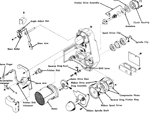
Ribbon Drive Unit ~ ~ c
-~~Ribbon Drive Gear Reduction Housing
Aux. Ribbon Correction Device (Opt) or Skew Device (Mod. 3)
3 Chain Drive
Train Drive (Mod. 3)
Troin {Mod. 3)
Forms Cart
-~.
).M. ROUTINE 2I
LUBRICATION
Fill right oil reservoir in T-ca !"ing IBM fl6
Bearing oil CI ps (2 oil cups) IB M #6 (8 drops each
Toggle plate anchor IBM #
All gears Lu~
All bearings,
IBM fl6. Fri(
ball IBM fl6.
Without oil-I to cup on top cup). With ( to oil-level f
light film of and gears.
light film of
1. light filn pinion, jl
2. Add #22 (see lubri'
light fi 1m Lli
Fill oi I reser', P/N 856381
cup).
pivot IBM #6. R 24. Skew roller
riplate *70 greas pivots, <:md c lut tion-disk interpo
evel hole: 1/80 (may have screw ii-level hole: F ole. Replace sc
'verse togg Ie )ivot IBM f6.
! (light filrn). ;h shafts ;er stud and
mce IBM 1'16 instead of II with IBM fl6
ew.
Lubriplate #700 "I eccentrici
Lubriplare #70 on I eccentrici
Lubriplclte #70: termediClte, and
o bevel gear uni cating Bevel Gea
briplate #70 on d
oir with special
drive key" drum geanl.
r Unit)
rive key.
ubricant,
CLEAN
Clean type with vacuum cleaner as required. Clean typeface wi th IBM cleaner, P/N 451529
Wipe excessive oil and grease from all areas to prevent contaminating ribbon"
Keep friction reverse-drag surfaces clil free. Wipe excessive oi I and grease from all surfaces to pre-vent ccmtamination of ribbon ..
OBSERVE
I
I
Check that reservoir never runs dry. Check that oi I reaches the chain. Check for chain binds. If bind is detected, perform off-c:artridge cleani ng.
Check that oil is available at end of wick I
I
in m'Jvable base. Check by pressing a whit,e piece of paper against the wick. A light oil film on the paper indicates suf- I
I ficient lubrication.
I
I I Check for wear and correct ribbon reverse and skew operation.
I
Check for wear and binds. Check for
I
corn~ct operation.
I
~
Check accumulated slug to slug clearance. Free, train movement with .001" between butts of two type slugs. Slight binds in train with .003" gage.
~ ~. ~ ~ ~
~
a
~. ~e.
a
(t) t:l $l:> t:ln (t)
~ §
g.
(t) ..-.. s; ~ .......
o ~ -;:a $l:> ::+ to o ...., ~4 Hammer Unit 6 Use IBM 116 on hammer-magnet armature pivots. Use light film IBM #6 on armature backstops and hammer surfaces that contact armatures. Do not atomize.
Hammer Unit No lubrication required {Mod. 3)
Strip Residual
Hammer Unit Blower
6 Chain
Drum
Timing Disk {Mod. 3)
Train Drive Fill train drive gear housing with IBM 1117 {Mod. 3) to just over the bottom of the gears.
1 Tractor Feed Light film Lubriplate 1170 on tractor drive pulleys, tractor shafts, and operating surface of tractor be I t.
Stacker Light film Lubriplate #70 on bevel drive gears and drive belt. Use IBM #6 on friction drive shaft.
Carriage Contact roll bearings IBM #6.
Tape-Read
8 Hydraulic Unit Blower Motor (2 oil cups) IBM 116.
6-8 line Drive Apply light fi 1m Lubriplate '70 on active surfaces of all gears, shiff fork, camming plate, and detent wheels. Apply IBM #6 on the detent arm pivots and rollers. Lubricate whenever this area is entered on a service call.
7 Frame T-Casting Use I ight film Lubriplate '70 on active Phenolic Support surfaces of gears, sl ides, guides, and levers. Chock Use IBM 116 on bearings, bushings, and
pivots.
Clean armature backstops Check for loose hammers and magnet coils. before applying IBM 116. Check for worn hammer-magnet residuals
and worn armature pivots.
Check that pushrods are free and straight. Check that armatures, hammers, and forms compressors are free to pivot.
Replace Do not allow strip to wear through.
Replace blower air-filter as necessary •
Perform off-cartridge Check for correct chain tension. chain cleaning
Scope drum head output (ground to one side of read head) • Should be 50-150 mv. Adjust head-to-drum clearance as necessary. Mod 6 - 40-150 mv •
Scope disk head output for 50-150 mv. (on leg to ground). Adjust head to disk gap to .001" to .002". (Do not go more than .002").
Check that grease is lubricating all gears.
Check tractor adjustments as required.
Clean as necessary Check for broken friction springs. Check for wear on friction drive roll.
Clean contact rolls Check tape brushes for bent or broken strands. Check brush tracking and all stop brush timings to E-l •
Check timing belt tension. When leakage is apparent, check for correct hydraulic fluid level (approximately to bottom of coils).
Check 6-8 line detent retaining collars for loose setscrews.
5. Check for fluid in the hydraulic reservoir (1 gallon, part 477567).
6. Install the signal cable shoe-connectors (SC-1 and SC-2) in the proper receptacles. Connector SC-1 has gold-plated contacts and should be inserted into the front receptacle.
On the Model 3, remove the cartridge blower hose to permit insertion of SC-1, after which you must reconnect the hose.
7. Install two antiwalk feet.
8. Assemble the forms-cart right- and left-grounding guide assemblies.
9. Check all terminal-block safety shields for warp-age before turning machine power on.
10. To insure correct machine performance, it is most important to check the .100" spacing between the cartridge and the hammer unit on the Model 3 printer (Figure 2). This is a critical dimension. If it has shifted during shipment, print quality can be drastically affected. Check this adjustment care-fully at both ends and readjust if necessary. (Refer to Figure 18 for other models.)
Line Voltage Wiring Check
Before connecting the power plug to the printer:
!. Determine actual customer line voltage being sup-plied. If a change is necessary, proceed with steps 2 and 3.
2. For line voltages nearest to 208 volts:
a. Place the chain-drive-motor machine cable on terminals TB-7-1, 7-2, and 7-3. (TB-7 is on the T -casting, to the right of the chain-drive motor, under the chain cartridge and under the ribbon.)
Train Type Slug
Locating Block
. 100"
Figure 2. Train-to-Hammer Unit Positioning
b. Place one ac lead for the elapsed time meter on terminal 4. The other ac lead will remain on ter-minal!. The ac terminal block is inside the meter cover. To check or change these ac line connec-tions requires a retainer (part 740489).
3. For line voltages nearest to 230 volts:
a. Place the chain-drive-motor machine cable on terminals TB-7 -4, 7-5, and 7-6.
b. Place one ac lead for the elapsed time meter on terminal 5. The other ac lead will remain on ter-minal1.
Three-Phase Motor Rotation Check
1. \Vhen the system is ready, turn on the system power, with the T-casting open.
2. Check carriage-motor rotation by observing the ro-tation of the forms stacker rolls. Correct roro-tation causes paper to stack properly. An mM card placed between the rolls before power is turned on will give an immediate indication of stacker roll rotation. The card should eject downward.
3. Close the T -casting and check the direction of the rotation of the type-train drive motor. The motor rotation is correct if the train moves counterclock-wise when viewed from the top.
4. :Make sure the hammer unit blower is blowing air
normally into the hammer unit. Some air flow will
be felt even if the blower is turning in the wrong direction. Also, make sure the type-train blower is blowing air.
5. Turn off the system power. Do not use the mainline CE switch on the 1403 (toggle switch inside rear cover). This switch should be used only if the sys-tem power is off.
6. If all three-phase motors are rotating in the correct direction, proceed to System Check-Out. If one
motor is rotating incorrectly, go to step 7. If all
motors are rotating incorrectly, proceed as follows:
a. Turn off the system power.
b. Tum off the power to the wall receptacle.
c. Reverse any two leads at the wall plug, or at the system power-input circuit breaker .
7. If one of the three-phase motors is turning in a di-rection of rotation that is incorrect:
a. Tum off the system power. (Pull the power-plug out of the printer.)
b. Interchange any two of the three leads of the motor.
c. Turn on system power and recheck motor rota-tion.
Carriage Control-Tape Brush Timing
Check the dynamic adjustment of the carriage tape
brushes using a tape punched on the customer's tape
punch. Refer to Dynamic Adiustment of the Carriage-Tape Brushes.
System Check-Out
1. Check for the correct operation of all printer inter-locks:
Gate (T -casting) Brush
Shift (6-8 line)
End of fonns Fonns check Thennal
Observe lights on both printer indicator panels while actuating interlock switches.
2. Check and record the read-head output on one of the oscilloscope waveform charts (see Figure 110 in the Appendix). It can then be retained for future reference. The output should be 50-150 millivolts for each leg.
Scope between dc ground (pin J) and pins B and
D of SA-1 for this reading (see Figure 92). The phasing of the PSS pulses to the differential ampli-fier in the system is extremely important. This can be checked by syncing internal-plus on the output of the differential amplifier, and observing several pulses. The phasing of the PSS pulse is correct if the differential-amplifier output pulse is stable and has a rise time of less than .5 microseconds. A waterfall effect is permissible at the trailing edge of this
out-put. (Refer to Timing Disk Transducer
Adiust-ments.)
Note: Reversal of the transducer leads will alter the length of the output pulse.
3. If the printer is being installed with an existing
sys-tem, or is a field merge, or field interchange, the
carriage control circuits for single-, double-, and triple-spacing must be adjusted. (Refer to section on
Single-Shots. )
4. Give the printer a complete operational test, using test decks 2000, 2010) 2012 and 2020.
Process ~eter Test
All printers are equipped with a process meter. This
meter will record time if the system processing unit
meter is recording, and if a first print instruction has been received by the printer from the system. A stop condition is established when the printer space key or restore key is manually operated and released, or when the system processing meter stops recording. However, as long as the space or restore key is held down, the meter will record time, provided the system processing unit meter is also recording time. The printer meter stops when the space or restore key is released.
Once started, the printer meter starts and stops with the system start and stop keys, regardless of the pro-gram function, provided no printer stop condition occurs.
Check the printer process meter to see whether it is functioning properly. Use the following test pro-cedure:
1. Enter at address 444 the instruction 2B449H445_. This will print one line and branch to a loop, which will keep the process M (- U) line active, although the printer will not continue to print.
2. Operate the system start and stop keys. Note that the printer meter starts and stops under control of the system start and stop keys although no printing is taking place.
3. With the printer meter running (because the pro-gram is operating in a branch loop), press the space key and hold it down. The printer meter should not stop recording.
4. Release the space key, and the printer meter should stop.
Service Procedures
Cover
Removal
Top Cover
1. Remove the front cover.
2. Remove the rear cover.
3. Loosen, but do not remove the mounting screws at the rear of the top cover.
4. Tilt the cover down until the left and right stay arms can be unhooked.
5. Unhook the stay arms.
6. Lift the cover, and free it from the rear mounting screws.
7. Replace in reverse order.
Top Forms Guide
1. Lift the front cover.
2. Snap the top forms guide out of the front plastic supports.
3. Raise the front end of the guide.
5. Unhook the rear end of the guide at the right.
6. Slide the guide off the left rear stud.
7. Remove the guide.
8. Replace in reverse order.
Front Cover
1. Raise the cover.
2. Compress the spring on the stay-arm stud and move the stud to the right.
"" ,..., -1. .1 • - 1 . 1 . , 1 .1 •
v. .lIn: {ue cover up unn1 Ine sma Clears tne sray-arm.
4. Remove the retaining clip and slide out the hinge pin.
5. Slide the cover to the right and off the left pivot.
6. Reinstall the cover in reverse order.
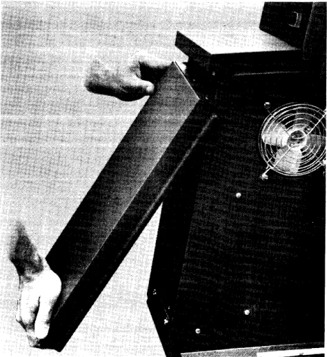
Left Front Cover Panel
(Model 3 and Numeric Printers Only)
Pull the bottom of the panel (Figure 3) forward until it clears its snap latch, then pull downward until the
top of the cover clears the two locating pins that go through the holes in the top of the panel.
To replace, slide the cover upwards, guiding the lo-cating pins through the holes in the top of the panel. When the panel is up all the way, push the bottom to-wards the rear of the machine until it snaps into place.
Inner Front Cover
1. Remove the following knobs:
a. Manual-clutch and line-selection knob. b. Forms-width vernier knob.
c. Manual-advance knob.
2. Remove the CE indicator panel on the inner front cover.
3. Remove the inner-front-cover holding screws.
4. Remove the cover.
5. Replace in reverse order.
Top Cover Adiustment
(Printers without Torsion Bars)
Adjust the spanner-type nut on the stay arms for cor-rect spring tension. The tension is corcor-rect if the cover just closes by its own weight to a point where it aligns with the shelf on the upper-left cover assembly. The
,"~~n:~~ nh~ •• l...l _nn •• __ L1..._L L1... _ L _ _ _ _ _ _ _ _ '11 •
I.C;U.3.lVU .3UVU.lU i:l::>::>Ule:; Uli:lL LHe:; lUJ:.' cuyer Wlli remam
open in the raised position.
[image:10.612.301.538.447.706.2]Lock Lever
Figure 4. Translator Frame Lock Lever
Manual Controls: Adjustment
Translator Lock-Lever
The lever must operate with a positive locking action when a force of four to seven pounds is applied at the center of the knob and perpendicular to the handle. Adjust as follows (Figure 4):
1. Loosen the translating-frame gib locknut.
2. Loosen the frame locking setscrew for gib-to-tie-bar clearance.
3. Lower the lock lever to the fully-locked position and recheck for gib-to-tie-bar clearance.
4. Press the locking mechanism to the rear of the machine while holding the locking roller squarely against the tie bar.
5. Turn the frame locking setscrew finger tight.
Note: Make sure the locknut is not against the lock block.
6. Tighten the setscrew 900
to 1500
•
7. Tighten the locknut.
Translator Vernier Knob
Set the vernier to provide a movement of ~" (± J{l').
1. Clamp the translator vernier knob against the shoulder of the vernier screw (Figure 5).
2. Position the right retaining collar against the knob, and clamp the collar to the vernier screw.
3. Position the left retaining collar so that a total end play of .0005" to .002" exists between the two col-lars and the translator-lock lever, and clamp the
collar to the vernier screw.
Note: On late machines, the left collar is pinned. Adjust
this clearance by using the right collar.
4. Tighten the setscrews in the translator-frame bear-ing to provide a slight drag on the vernier screw.
Locking Roller Tie Bar
Setscrew
Gib
Apply Loctite* sealant to the setscrew threads if this adjustment is made.
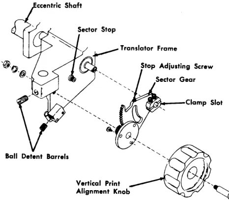
Vertical Print-Alignment Knob
1. Position the eccentric shaft (Figure 6).
a. The slot in the right end should be parallel with the slot in the sector-gear hub, within "44". b. Further adjustments may require that this be
altered.
2. Position each ball-detent barrel to the periphery of the sector gear:
a. For clearance throughout full gear rotation. b. For maximum clearance of .008".
Note: When installing a new ball-detent barrel, insert
the new barrel from the sector-gear side of the mounting block. This method avoids stripping off too much locking material on initial installation.
*Loctite is a product of the American Sealant Company
Translator Frame
Figure 5. Translator Vemier
I •
'N
loOk 51.evoTranslato~((l;;)
Lock Lever ~~
R;ght Coilo, / " ~
Translator
Vertical Print Alignment Knob
~r~--Clamp Slot
Figure 6. Vertical Print-Alignment Knob
3. Lock the translator frame.
4. Check for a bind between the bottom of the vernier screw and the lock sleeve of the translator vernier (see Figure 5).
a. Raise the translator frame to its uppermost po-sition.
b. Tum the translator vernier knob to detect a bind.
5. If a bind is not detected, proceed to step 7.
6. Remove the bind between the bottom of the vernier screw and the lock sleeve of the translator vernier.
a. Loosen the clamp screws in the sector-gear hub. b. Tum the eccentric shaft counterclockwise until
the bind is eliminated. c. Tighten the clamp screws.
7. Adjust the sector-gear stop screw:
a. For a minimum clearance of ~" between the
translator frame and the printer casting.
b. For a minimum clearance of ~2" between the
lower edge of the sector gear and the printer casting.
Print-Timing Dial
(Models 1, 2, 4, 5, and 6)
1. Place 4-part paper in the machine.
2. Load all H's, W's, or M's into storage for printing.
3. Program for PRINT AND BRANCH.
4. Select 8-lines-per-inch carriage mode and set the print-density lever at C.
12
5. Set the print-timing dial at:
a. 20 for Models 1 and 2. b. 15 for Models 4 and 5. c. 11 for Model 6.
Assume 4-part paper is .012" thick. If a
microme-ter is available, it is advisable to demicrome-termine the exact thickness and set the timing dial to the correct number as determined from the chart on the ribbon cover.
Note: There are three different print timing dial charts: Timing chart decal (part 475644) for Models 1 and 2 Timing chart decal (part 865912) for Models 4 and 5
Timing chart decal (part 889623) for the Model 6.
6. Run the machine for ten to twenty lines.
7. Examine the fourth copy. A faint smudge will be visible showing the outline of each hammer. The relative position of each printed character to the hammer can thus be examined and evaluated.
8. Adjust the timing-dial screw (Figure 7) until the maximum number of printed characters is centered on the hammer impression marks. Maintain the dial setting of:
a, 20 for Models 1 and 2, b. 15 for Models 4 and 5.
c. 11 for Model 6.
9. Individual positions are adjusted for centering by the hammer-magnet eccentric adjusting tool (part 451123).
Note: It may be necessary to compromise this adjust-ment to obtain acceptable print density. If the correct ham-mer flight time and print density cannot· be obtained, a new hammer-magnet assembly should be installed.
Forms-Width Vernier 1. Adjustment procedure:
a. ~fove the translator frame to the left. b. Remove knobs.
d. Remove the gear guard.
e. Locate the left forms tractors in the correspond-ing extreme left slots in the tractor mountcorrespond-ing bars.
f. Locate the right forms tractors in the corre-sponding extreme right holes in the face of the removable slides.
2. Adjust the left tractor-pin feeds horizontally.
[image:12.612.35.268.58.263.2], .
Figure 7. Print-Timing Dial Adjustment
b. Shift the tractor mounting bars to align the pin feeds within .005". There are two screws in each end of each bar (Figure 8).
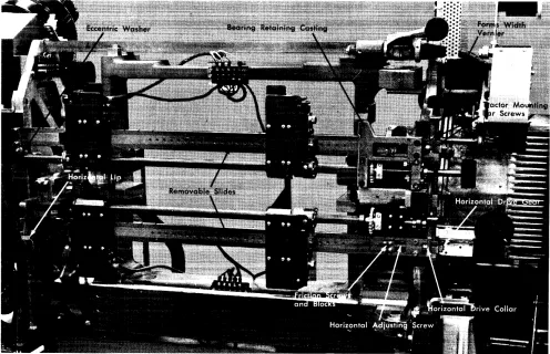
Figure 8. Tractors (T -Casting Removed)
[image:13.612.81.363.55.272.2] [image:13.612.83.579.383.703.2]mount-ing bar is positioned up and down by an eccentric washer on current machines. The upper and lower mounting bars must be paralle1.
3. Adjust the right tractor pin feeds.
a. Orient the horizontal adjusting screws, horizon-tal-drive collar, and gear to align the right pin feeds within .005", horizontally.
b. Place a straight edge along the pin feeds to check alignment.
c. Reposition (if necessary) the horizontal adjusting screws in relation to the conars and gears to ob-tain adjustment.
d. Position the collars and gears for a maximum end play of .002".
4. Operate the forms-width vernier with light finger force. Adjust the friction scre\v and block as re-quired.
5. After this adjustment has been made, adjust the vertical position of the right ends of the upper and lower tractor mounting bars for free movement of tractor assemblies.
Manual-Clutch and Line-Selection Knob
1. Preliminary procedure:
a. Move the translator frame to the left. b. Remove knobs.
c. Remove the front inner cover. d. Remove the gear guard.
2. Check the adjustment of the manual clutch and the line-selection-knob assembly (Figure 9).
a. Check for clearance:
(1) For a minimum-end piay of the dentent arms on the shaft.
(2) For a minimum of .025" between the detent roller and the detent wheel when the detent is inoperative. (3) Between the tines of the shift fork and the shift-gear hub.
b. Check for alignment of the:
(1) Detent arms to the slots in the camming plate. (2) Detent wheels to the detent arms.
c. Check for correct operation to make sure that:
(1) The clutch shifts from 6-line neutral to 6-line drive and from 8-line neutral to 8-line drive.
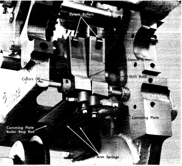
Figure 9. Manual-Clutch and Line-Selection Assembly (Lower Tractor Shaft Removed)
[image:14.612.35.393.381.709.2](2) The detent ann spring causes correct operation of the detent anns and wheels (there should be a force of
4!1 to 6!1 pounds on the detent ann).
(3) The detent arm roller seats fully in the detent wheel when the detent is operative.
3. If the conditions in step 2 are met, no further
ad-justment is necessary. Proceed to step 11. If not:
a. Unhook the detent-arm springs. b. Loosen both the detent wheels.
c. Slide the right detent wheel to the right. d. Loosen the detent-arm collars.
e. Slide the detent arms to the left.
f. Loosen the camming plate on the shift fork so that the plate is just free to slide.
g. Loosen the setscrew that holds the camming-plate roller stop rod.
h. Wedge some paper between the shift-fork tines and the hub of the shift gear to center the tines around the shift-gear hub.
4. Position the shift fork on the shift rack for gear mesh and clearance.
a. Detent the shift rack in 6-line drive at the right. b. Position the shift fork on the shift rack so that
the shift gear meshes with the 6-line driving and driven gears and has clearance to the casting. c. Rotate the shift fork around the shift rack to center the shift fork around the shift-gear hub. d. Clamp the shift fork to the shift rack.
5. Align the detent arms to the camming plate.
a. Set the shift gear to 6-line drive position.
b. Align the detent arms with the left two slots in the camming plate.
c. Tighten the collars to hold the detent arms in position.
6. Adjust for a clearance between the detent wheels and the detent arms of .025" with the manual clutch in either 6- or 8-line drive.
a. Turn the 6- and 8-line gear idler to a position where it does not move when the shift gear is shifted from the 6-line drive to the 8-line drive, or vice versa.
b. Set the shift gear to the 8-line neutral position. c. Slide the right detent wheel opposite the right
detent arm.
d. Use a rubber band to hold the right arm against the detent.
e. Adjust the camming-plate roller stop rod to provide a .025" clearance between the detent arm and the teeth of the right detent wheel.
f. Tighten the setscrew to hold the camming-plate roller stop rod.
g. Rehook the springs on the detent arms. h. Clamp the camming plate to the shift fork.
7. Align the detent wheels to the detent arms.
a. Set the manual clutch to 8-line neutral.
b. Align the left detent wheel to the left detent arm.
c. Clamp the left detent wheel to the tractor shaft. d. Set the manual clutch to 6-line neutral.
e. Align the right detent wheel to the right detent arm.
f. Clamp the right detent wheel to the tractor shaft.
g. Check the operation of the manual clutch for four manually operated spaces.
h. Readjust as necessary.
8. Set the spring tension to provide 4!1 to 6!1 pounds
force on the detent arm when it is engaged in the
detent wheel.
9. Remove the paper from between the shift-fork tines and the shift-gear hub.
10. Position the clutch-interlock switch.
a. The switch must transfer before the plunger completely clears all of the four grooves of the shift rack.
Note: The switch operating plunger must have a minimum of .005" clearance to the rack grooves when detented.
b. Position the switch to obtain this adjustment.
11. Replace the remaining parts in reverse order.
Forms Positioning
Tractor Shafts and Tractor Mounting Bars Removal
This procedure is given for the removal of the upper and lower tractors, the tractor mounting bars, and the
drive shafts. If only one set is to be removed, do only
as much of each step as will allow the desired set to be removed.
1. Remove the forms.
2. Remove the clip-on paper guides from the tractor mounting bars.
3. Remove the inner front cover.
5. Remove the jam contact mountings from the tractor mounting bars (early machines only).
6. Remove the wires from the form-stop contacts at the terminal block.
7. Shift the T -casting to the left.
8. Remove the gear guard.
Separate the vertical shaft of the forms-width vernier by loosening the setscrews in the vertical coupling of the forms-width vernier. Move the vertical coupling up onto the upper shaft and lock it to the shaft.
Remove the bearing retaining castings. See Figure 8.
l. Loosen the screws that prevent bearing end shake
(at the right).
2. Remove the two bearing-holding screws (at the right) for each bearing retaining casting.
3. Shift the T -casting to the right.
4. Remove the two holding screws (at the left) for
each bearing retaining casting (one screw is a dowel).
5. Remove both bearing retaining castings.
Remove the tractor mounting bar and the tractor shaft.
l. Remove the two screws and the slide-retainer plate
at the left end of one of the tractor mounting bars.
2. Remove the two holding screws at the right end of the same tractor mounting bar.
3. Lift the tractors, the mounting bar, and the shaft
out and to the left to clear the T-casting.
Repeat step 5 for the other assembly.
Individual Pin-Feed Removal
l. Open the T -casting.
2. Remove the forms.
3. Open the tractor door.
Remove the tractor paper guides.
l. Remove the tractor paper guide farthest from the
hinge of the door.
2. Remove the tractor guide on the other side of the pin feeds.
Align the pin-feed holding pins with the slot in the frame spacer plate (the end nearest the drive shaft)
Figure 10).
l. Turn the tractor shaft until one holding pin aligns
with the slot.
2. Use a similar pin to push the installed pin toward
the center of the machine (part 804671).
3. Repeat step 2 for the second holding pin.
Remo\rc the pin feed by lifting. Insert the ne,:l,' pin
feed.
Replace the pin-feed holding pins.
1. Insert the second pin.
2. Tum the tractor shaft until the first holding-pin
hole is aligned with the slot.
3. Insert the first pin.
Note: Pins are to be flush or slightly recessed.
Replace the tractor paper guides in reverse order
(see Forms-Tractor Adiustment).
Forms-Tractor Adiustment
Adjust the belt tension.
1. Maintain parallelism between the axes of rotation of the drive sprocket and of the movable sprocket
(Figure 11).
2. Position the movable-sprocket stud for a minimum slack at the point of tightest engagement.
a. Ensure that belt tension is not excessive. b. Tighten the sprocket stud.
Position the beveled ramps.
1. The point of the ramp must point in the direction
opposite to the belt motion.
2. Position the ramp for a clearance of .002" to .007" to the respective sprocket hub,
3. Clamp in position.
Position the tractor paper guides.
l. Align the edge of the paper guide nearest the door
pivot plate Hush to the pivot plate.
Figure 10. Tractor (Upper Left)
3. With the conditions in steps 1 and 2 established, secure both paper guide and mounting block with their front surfaces Hush to the front edge of the spacer plate.
4. Position the lower edge of the adjacent paper guide against the lower edge of the paper guide nearest the door pivot, maintaining the upper edges par-allel. Check that the inner edges of the guides are clear of the pins.
5. Fasten the adjacent paper guide to the tractor frame.
Position the tractor door for a clearance of paper guide plates to the door runners of .048" to .056" (Figure 12).
1. Loosen the pivot plate.
Note: The Loctite sealant must be used on the threads of the holding screws if this adjustment is made.)
2. Screw the door stop in below the correct door setting.
Figure 11. Tractor Assembly
4. Force the door against the feeler gages.
5. Tighten the pivot plate.
6. Set the door stop to hold the door at the correct clearance.
Pivot Plate Mounting Screws
Figure 12. Tractor Door Clearance
18
Cover Stop Set Screw
form-stop lever is within ~l' of the front surface of
the paper guide.
Tractor-Mounted Jam-Detection Device Adiustment
Some additional adjustments are applicable to forms tractors that have tractor-mounted jam-detection de-vices.
1. Adjust the detection setscrew so that the jam-detection switch breaks when the door is opened a
total of .095" to .118" (Figure 13).
2. Adjust the slide support plate to limit the tractor door open position. Place a straight edge against the belt-guide step perpendicular to the tractor guide plate as shown in Figure 14. Adjust the slide
support plate to obtain ~" ± ~" clearance between
the door and the straight edge. Be sure to maintain proper belt tension when tightening the plate hold-ing nut.
Upper and Lower Tractor Drive-Shaft Positions
First, check the forms-width vernier. Prepare to adjust the drive shafts.
()
.095"- .118"
Door Opening
Figure 13. Jam-Detection Switch Adjustment
2. Position the right fonns tractors in the correspond-ing holes in the face of the movable slides.
3. Place a fonn in the fonns tractors.
Check the position of the upper drive shaft to the lower tractor drive shaft. The fonn must fit in the
trac-Straightedge
b
~h
3/32" ~ 1/32"
C.~_ ... ~~'./
Figure 14. Tractor Door Opening Limit
tors with a minimum slack in paper. Feed the forms manually and check for no elongation of the pin-feed holes (this may occur under power).
The upper tractor pins should touch the upper edge of the pin feed holes in the form. The lower tractor. pins should touch the lower edge of the pin feed holes in the form.
If fonns are tighter on one side than the other,
ad-just the left end of the upper mounting bar by means of the eccentric washer (on current machines). See Figure 8.
If necessary, adjust the upper tractor shaft drive in
relation to the lower tractor drive shaft.
1. Loosen the upper tractor shaft drive gear.
2. Manually rotate the shaft to remove slack.
3. Clamp the drive gear to the shaft.
Replace any remaining parts in reverse order.
Tractor Installation
This procedure refers to both the upper and the lower assembly. Place the tractor shaft and the mounting bar in relative positions on a flat surface.
Install the tractors on the drive shaft.
1. Slide the drive shaft through the square drive hub on the right tractor.
2. Turn the left tractor drive until the pins line up with those on the right tractor and, at the same time, the drive hub lines up with the drive shaft.
Note: These pins line up at only one point during one revolution of the drive shaft.
3. Slide the drive shaft through the square drive hub on the left tractor.
Install the tractors on the mounting bar. Slide the mounting bar through right and left tractors.
Tractor-Shaft and Mounting-Bar Replacement
Place the tractors, the mounting bar, and the tractor shaft in the machine.
1. Set the assembly in the machine.
2. Insert the screws in the slide retainer plate and the mounting bar at the left and turn the screws in a few turns.
Repeat for the other assembly.
Install the bearing retaining castings.
1. Slide the bearing and bearing retainer ring in posi-tion. New machines do not have the bearing re-tainer ring.
2. Place the bearing retaining casting in position.
3. Insert the two right holding screws and tighten un-til almost snug.
4. Insert the two left holding screws and tighten.
5. Snug up the bearing-end screws.
6. Tighten the right bearing-retaining casting-holding screws.
7. Tighten the bearing-end screws.
Repeat this step for the other assembly.
Position the tractor mounting bars.
1. Slide the tractors apart to extreme positions.
2. Position the tractor mounting bars against the lip and eccentric washer on the printer casting at the left.
3. Shift the mounting bars horizontally to vertically position the left tractor pins on the upper mountLl1g bar within .005" of the left tractor pins on the lower mounting bar. Use a straightedge laid along the tractor pins for determining vertical alignment.
Connect the vertical shaft of the forms-width ver-nier.
1. Loosen the setscrews in the vertical coupling and slide into engagement with the upper and lower shaft.
2. Clamp the coupling to both shafts.
Perform the following adjustments:
1. Adjust the forms-width vernier.
2. Position the upper and lower tractor drive shafts.
Replace the remaining parts in reverse order.
Tractor Jam-Detection Device Adiustment (Old Style)
This applies to both upper and lower detection de-vices of machines that are not equipped with tractor-mounted jam-detection devices.
20
Check the jam-detection device.
l. The jam bail must rest against both the left and
right tractor doors.
2. The rear of the bail mounting brackets must be flush to the rear of the forms support bar.
3. When applied at the operating edge of the bail, the bail movement must be free.
4. A force of ~ pound (225 grams) must move the
bail away from the tractor door.
5. The switch plunger must be .010" to .015" past the toggle point when the bail is resting against the tractor doors.
6. The switch plunger must be free of the bail when the tractor doors are opened against the forms-guide support bar.
If these conditions in step 2 are met, no further
adjustment is necessary.
Adjust the jam-detection bail.
l. Loosen the bail mounting brackets.
2. Rest the bail against both forms-tractors.
3. Position the rear edge of the mounting bracket flush to the real' side of the forms-guide support bar within .005".
4. Tighten the mounting bracket in position.
Adjust the bail torsion spring.
l. Loosen the locknut on the spring stud.
2. Turn the screw and tighten the locknut.
3. Check for a ~ pound force to move the bail away
from the tractors.
4. Readjust as necessary.
Position the bail switch.
1. Loosen the holding screws.
2. Be sure the jam bar is against the tractor cover.
3. Locate the switch so that the switch plunger is moved .010" to .015" past the toggle point.
4. Tighten the ho!dLTlg screws.
Forms-Stacker Assembly Adiustment
For the gravity-stacking device and single-speed stacker, disregard the adjustments that are not ap-plicable.
l. Stacker tension springs are to be adjusted to the
compress-ing the sprcompress-ings. (Too much tension will tear the paper.) Be sure the slotted end of the spring is looped down from the top and placed directly un-der the curved nut.
2. The bevel gears on the countershaft assembly, and the friction drive-shaft assembly are to be posi-tioned for .002" to .004" wink and alignment of the crown points of each gear (full-tooth engagement).
Note: Late machines do not have bevel gears.
3. If the teeth do not engage correctly, both shafts
will have to be repositioned. Check again for .002" to .004" wink after obtaining the correct tooth en-gagement.
Base Adjustments and Removals
Grounding of Forms Carts
Adjust the forms-cart guides so that their contact springs press firmly against the sides of both the front and rear carts when they are in position. Late ma-chines have fixed grounding assemblies, which require no adjustment.
Left Shock-Mount Leveling
Level the left shock-mount support casting so that it is
parallel to the printer casting within Ye" in the:
1. Left-to-right plane.
2. Front-to-back plane.
Adjust the two front and back jackscrews to obtain this.
Translator-Frame Removal
1. Remove the forms.
2. Remove the top paper guide.
3. Remove the paper guide at the bottom of the trans-lator frame.
4. Remove the front paper guide (below the translator frame).
5. Remove the ground wire to the translator frame.
6. Lower the translator frame to the lowest position with the vertical-print-alignment knob.
7. Remove the bumper stop stud:
a. From the left end of the translator frame. b. From the right end of the translator frame.
Remove the tractor shafts and the tractor mounting bars. Remove the T -casting. Remove the hammer unit assembly.
Free the translator frame.
1. Remove both eccentric stop studs at the bottom rear of the translator frame.
2. Loosen both eccentric stop studs at the bottom front of the translator frame.
3. Remove the clip on the translator vernier shaft (a screw and washer on late machines). See Figure 5.
4. Unscrew the vernier shaft from the translator frame.
5. Move the translator lock lever to the extreme right.
6. Remove the stop blocks at the top front of the trans-lator frame.
Remove the translator frame.
1. Lift the translator frame just enough to take the full weight of the frame.
2. Slide the bottom of the frame so that the frame is clear of the printer casting.
3. Tilt the top of the frame to the rear, and withdraw the frame from the front of the machine.
Reinstall in reverse order.
Perform the following adjustments:
1. Position the translator frame.
2. Position the T-casting front to rear.
3. Position the T -casting vertically.
Replace the remaining parts in reverse order.
Translator-Frame Positioning
Check that the six guide rollers rest against their re-spective guiding surfaces. Adjust for .005" minimum clearance between the printer casting and:
1. Upper front guide blocks.
2. Lower rear guide studs.
3. Lower front guide studs.
Movable-Base Removal
1. Remove the ribbon.
2. Remove the cartridge assembly.
3. Remove the cover over the terminal block on the rear of the T -casting.
4. Remove the cover over the read-head assembly.
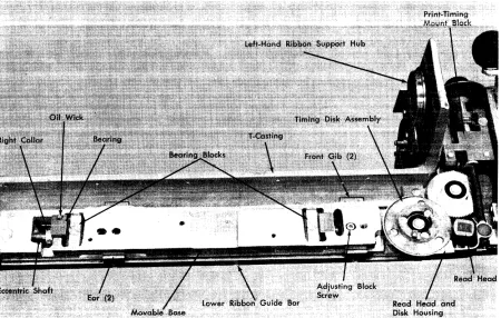
5. Remove the read head (Figure 15).
6. Remove the timing-disk assembly by removing the one screw from the bottom.
7. Remove the read head and disk housing.
8. Remove the two screws that attach the print-timing mount block to the movable base.
Figure 15. Movable Base
9. Remove the screws in the front cover of the print-timing dial.
10. Remove the screws in the movable-base front gibs.
11. Remove the lower ribbon guide bar.
12. vVork enough slack in the read-head cable
{un-tape the cables if necessary) to allow the movable
base to be lifted clear of the T -casting.
Remove the movable base.
1. Carefully lift the base up off the eccentric-bearing blocks.
2. Carefully raise the base so that the print-control-dial assembly clears the T-casting lock lever so read-head cable is not damaged.
[image:22.612.40.490.419.705.2]Figure 16. T -Casting (Movable Base Removed)
Movable-Base Eccentric-Shaft Removal
1. Remove the movable base. See Figure 15.
2. Remove the print-density indicating block (see Fig-ure 17).
Free the movable-base eccentric shaft.
l. Support the right end of the eccentric shaft and
drive out the taper pin (the small end is up) in the print-density lever assembly.
2. Remove the lever assembly from the shaft.
3. Remove the friction clamp from the right end of the shaft.
Note: The friction clamp provides the necessary friction to hold the print-density lever in position (A to E) without binding. The shaft must move in the friction clamp for operator setting of the lever.
4. Loosen the screws in the collar (See Figure 15) that holds the right bearing, and slide the collar to the right.
5. Remove the screws underneath that hold the left and the right bearing blocks to the T -casting.
Remove the eccentric shaft.
1. Lift the left end of the eccentric shaft so that it clears the T -casting.
2. Withdraw the shaft to the left, carefully sliding the shaft through the right bearing and bearing block.
Warning: The right bearing holds the oil line and
the wick that oils the type chain.
Replace the movable-base eccentric shaft in reverse order and adjust the movable base during assembly.
Movable-Base Adiustment
Remove the ribbon and the chain cartridge.
Check the adjustment of the movable base.
1. The two eccentric-shaft bearing blocks are seated against the front shoulders of the recess in the T-casting with a maximum allowable gap of .001" (Figure 16).
2. A wink of .001" to .003" exists between the motor
drive gear and the chain-drive idler gear at the
point of tightest engagement.
3. The movable base sits on the T-casting with a maxi-mum vertical clearance of .001".
4. The movable base slides freely in the horizontal plane with a maximum vertical movement of .001".
If the conditions just stated are met, no further
ad-justment is necessary. Replace the remaining parts in reverse order. Remove the cover over the terminal block on the rear of the T -casting.
Adjust the clearance of the eccentric-shaft bearing
blocks to the front shoulders of the recesses in the
T-casting.
l. Set the print-density control lever to E.
2. Loosen the mounting screws (under the T-casting) for the eccentric-shaft bearing block.
3. Position the blocks against the front recess in the T -casting with a maximum clearance of .001".
Adjust the movable base to the T -casting for a maximum clearance of .001".
1. Tighten the two front gibs (See Figure 15) that hold
the movable plate to the T -casting (screws under T -casting).
2. Loosen the screws in the lower ribbon-guide bar (two ears hold the movable base against the T-casting).
3. Press down hard on the movable base.
4. Press the ears of the lower ribbon-guide bar against the movable base.
5. Tighten the screws in the lower ribbon-guide bar while maintaining pressure as stated in steps 3 and 4.
Adjust the clearance of the motor drive gear to the type idler gear. (The chain cartridge was previously removed.)
1. Loosen the adjusting-block screw. (The block is
under the movable base and fits over the stud in the T -casting. It positions the movable base right to left.)
2. Turn the idler gear to obtain the tightest mesh with
the motor drive gear.
3. Slide the movable base left to right to obtain a wink
between the idler gear and the motor drive gear of
.001" to .003" at the pOint of tightest engagement.
4. Tighten the adjusting-block screw and recheck the
clearance. Wink must be present with no stress on the motor shaft.
Replace the remaining parts in reverse order.
T -Casting Removal
l. Remove the ribbon.
2. Remove the ribbon-drive unit.
3. Remove the chain cartridge.
4. Remove the wires to the T -casting.
5. Remove the front cover.
6. Remove the right cover.
7. Remove the inner front cover.
24
Remove the movable base (or remove the read head).
Free the hinge pin (Figure 17).
1. Open the T -casting.
2. Remove the ribbon shield and print-line indicator from the hinge.
3. Remove the screw that is screwed into the hinge
pin through the horizontal hole in the upper arm of the T -casting.
4. From the rear side of the T-casting, drive pins from the:
a. Upper eccentric bearing b. Lower eccentric bearing.
5. Loosen the collars on the hinge pin.
6. Carefully close and lock the T -casting.
7. Loosen the setscrew in the upper hinge-pin bushing.
8. Loosen the setscrew that locks the lower eccentric
bearing.
Remove the T -casting.
l. Remove the hinge pin and catch the parts as they
are freed by the hinge pin.
2. Unlock the T-casting while supporting the weight of the casting.
3. Slide the T -casting out toward the front to clear the
translator frame.
T -Casting Replacement
Prepare to reinstall the T -casting.
L Ensure that the hinge pin will slide through all
parts.
2. Slide the hinge pin through the upper bearing hole in the T -casting.
3. Thread the upper eccentric bearing on the hinge pin.
4. Thread the lower eccentric bearing on the hinge pin.
Figure 17. T-Casting (Hinge-Pin End)
Locate the eccentric bearings in the T -casting to enable, in a later step after the T-casting has been installed, the pinning of bearings to the hinge pin.
l. Locate the lower eccentric bearing rotationally.
a. Rotate the bearing around the hinge pin so that the high side of the eccentric is to the right.
b. Further rotate the bearing so that the high side
of the eccentric rotates 450
toward the rear.
c. Work the eccentric into the lower bearing hole.
d. Insert the taper pin (finger tight) into the bearing and the hinge pin.
2. Locate the upper eccentric bearing rotationally.
a. Rotate the upper bearing around the hinge pin until it lines up with the upper bearing hole.
b. Work the bearing into the upper hole.
c. Insert the taper pin (finger tight) into the bear-ing and the hbear-inge pin.
3. Position the bearings vertically.
b. Insert the setscrew and lock the lower eccentric bearing to the lower arm of the T -casting. c. Remove the taper pins.
d. vVithdraw the hinge pin.
Prepare the translator frame for the T -casting re-placement.
1. Place the bushing in the upper arm of the
trans-lator frame and lock the bushing as high as possible in the arm.
2. Piace the thrust washer over the jackscrew in the
lower arm of the translator frame, align the hole centers, and tape the washer to the jackscrew.
Set the T -casting into position.
1. Gather all loose parts that fasten to the hinge pin
(including the hinge pin) and set them on the printer so they will be close at hand when needed.
2. Lift the T -casting into position on the translator
frame, keeping the right end high so the thrust washer is not dislodged.
3. Actuate the T ~casting lock lever until the latch just
engages the latch catch.
Install the hinge pin.
1. Slide the hinge pin through the bushing in the upper
arm of the translator frame.
2. Slide the hinge pin through the upper eccentric bearing in the upper arm of the T -casting.
3. Thread the hinge pin through the loose parts in
correct order and in correct relation to the T -casting.
4. Slide the hinge pin into the lower eccentric bearing.
5. Slide the hinge pin through the thrust washer into the jackscrew.
Fasten the eccentric bearings to the hinge pin.
1. Align the lower pin hole in the hinge pin to the pin hoie in the iower bearing.
2. Insert the taper pin into the holes just aligned.
3. Align the pin hole in the upper eccentric bearing to the upper pin hole in the hinge pin.
4. Insert the taper pin into the holes just aligned.
5. Drive in both taper pins.
Position the hinge pin.
1. Turn the binge pin until the high side of the eccen-trics are to the right.
2. Insert the screw through the hole in the upper arm of the T -casting, and screw through the hinge pin.
3. Free the bushing in the upper arm of the translator
frame, and force the bushing against the T -casting.
Perform these adjustments:
1. Position the T-casting front to rear.
2. Position the T-casting vertically.
3. Adjust the ribbon-shield assembly.
Replace the remaining parts in reverse order.
Horizontal T -Casting Positioning (Chain-to-Hammers)
Before making this adjustment, you must position the hammer unit correctly, front to rear, and adjust the cartridge and movable base correctly on the T -casting.
Refer to Aligning the Hammers to the Paper Path.
The adjustable stop stud can wear into the T -casting
nn.'I'IC"';'r\,""" l"CtC" "t "., nnCt .. .;""',... l,... ... nh..: ... ,.., 7"'\, ... ..t:u~Ct'l' ... ~ "' ... ,.1 nl...n"",n' '-<1U".1U5 .1V"" V.1 .L -'-<1"'-.1.1.15 .1<1'-'-.1.1.1U5 'p.1~""U.1~ <1UU
'-.1.1<1U5-ing the hammer-to-chain adjustment. If this condition
is observed~ install field T-casting strike plate (B/M
485176). Newer machines have this plate.
Check for any foreign material between the strike plate and the T -casting.
Also check the cartridge mounting as follows: Loosen the four holding screws, and while holding the cartridge toward the front of the machine (the direc-tion the hammers tend to push it) retighten the screws. This prevents possible change of hammer-to-chain relationship due to any clearance that might exist between the cartridge aligning pin and the guide hole in the movable base.
1. Remove the ribbon guide wire. Remove the
ham-mer unit cover.
2. Remove the ribbon and set the density control on
E. Insert the .083" rod end of the tool (part 451615)
between the hammer faces and the chain at the right (and also the left) end of the cartridge (Fig-ure 18).
Note: Do not confuse this with a similar adjustment made with a similar tool on the Model 3 printer (see Figure 2),
3. Increase the density setting until a light drag on
the tool is obtained. If the clearance is correct, the
density control should be at C setting.
4. If incorrect on the right end of the T -casting,
per-form step 5. If incorrect on the left end of the
Figure 18. Chain-to-Hammer Positioning
5. To adjust the right end of the T -casting, loosen the setscrew on the inside of the T -casting hinge pin at the lower end. Close the T -casting and loosen the other locking setscrew, which is accessible with the T -casting closed. Rotate the T -casting hinge pin until a light drag on the tool is obtained at C density. Lock the hinge pin with the setscrew.
6. Adjust the left end of the T -casting by loosening the locknut and positioning the adjustable stop stud until a light drag on the tool is obtained at C density.
Note: Following steps 5 and 6, the .083" dimension between the hammers and chain should be rechecked at both ends of the cartridge.
7. The T-casting latch may require adjusting for sufficient tension of the casting on the stop stud to maintain the T -casting latched. Loosen the two holding screws at the side of the latch and adjust the allen-head screw from the rear of the printer.
8. Tighten the T-casting hinge-pin locking screw on the inside of the T -casting.
9. Replace the ribbon guide wire and replace the hammer unit cover and ribbon.
10. Run the machine at print-density C, printing all
H's on 4-part paper. Examine the fourth copy. If
one end still prints lighter than the other, adjust the T-casting hinge pin slightly to achieve uni-formity.
Vertical T-Casting Positioning
This adjustment depends on the correct location, front to rear, of the hammer unit and the correct adjust-ment of the type cartridge and movable base on the T-casting.
Prepare to position the T-casting vertically.
1. Use a two-part form and strip off the last copy,
leav-ing the last carbon exposed to the hammers.
2. Set up the processing unit to print one line of alter-nate W's and M's.
3. Remove the ribbon.
4. Latch the T -casting closed.
5. Set the print-density control lever to C.
6. Set the print-timing dial to:
a. 32 on Models 1 and 2, b. 24 on Models 4 and 5, c. 19 and Model 6.
Check the vertical positioning of the T -casting.
1. Print one line of alternate W's and M's.
2. Open the T -casting.
3. Remove the forms.
4. Observe the imprint of the characters on the ham-mers.
5. If the imprint is located evenly between the upper
and lower edges of the hammer faces, no further adjustment is necessary. Replace the ribbon.
Adjust the vertical position of the T -casting.
1. Position the right end of the T-casting.
a. Loosen the hinge-pin-bushing setscrew in the upper arm of the translator frame.
b. Loosen the lower jackscrew locknut on the lower right arm of the translator frame. See Figure 17. c. Tum the upper jackscrew locknut to obtain the
vertical adjustment.
d. Tighten the lower jackscrew locknut.
e. Force the hinge-pin bushing down and tighten the setscrew.
2. Position the left end of the T-casting.
a. Loosen the chock block (Figure 19) on the T-casting to obtain the vertical adjustment. b. Slide the chock block on the T -casting to obtain
the vertical adjustment.
c. Clamp the chock block to the T -casting.
3. Position the ribbon shield and the print-line indi-cator. Refer to that adjustment.
Chock Block
Interlock Detent
Figure 19. T -Casting Latch
T -Casting Latch Adiustment
Remove the interlock-switch cover. Check the adjust-ment of the T-casting latch (Figure 19).
1. Open the T-casting.
a. Operate the interlock detent and move the lock lever to the latched position (the handle resting against the stop stud).
b. Make sure the high side of the eccentric is toward the front and prOvides positive locking
action high side 80
(± 10
) above the horizontal.
c. Make sure the interlock switch just makes when
the latch handle is ~" to Kl' from the
iatch-handle stop stud.
2. Close the T -casting.
3. Make sure a two- to six-pound force (applied at the
center of the ball) is required to operate the latch.
\Vhen these conditions are met, no further adjust-ment is necessary. Replace the interlock-switch cover.
T.Casting
T ·Casting Lock Lever
/1
Position the eccentric shaft.
1. Open the T -casting.
2. Move the T-casting lock lever to the latched posi-tion (the handle resting against the stop stud).
3. Loosen the clamp screw in the handle.
4. Position the high side of the eccentric toward the front.
5. Further position the high side of the eccentric above the horizontal so the latch just provides a positive
locking action: 80
(± 10
) above the horizontal.
6. Clamp the handle to the eccentric shaft.
Adjust the interlock switch.
1. Position the latch handle
KI'
from the latch-handlestop stud in latching position.
2. Position the interlock-switch actuator on the eccen-tric shaft so that the interlock switch just makes.
Latch Bumper Screw
Figure 20. T -Casting Latch Catch
Translator Frame
Position the T-casting-Iatch catch (Figure 20).
1. Loosen the T-casting-Iatch catch holding screws.
2. Latch the T -casting closed.
3. Turn the T-casting-Iatch catch adjusting screw (socket head) to draw the T-casting against the latch bumper screw (hex head).
Adjust the latching force.
1. Tum in on the latch-catch adjusting screw J.<l' turn.
2. Tighten the holding screws.
3. Latch the T -casting and observe the latching force.
4. If the latching force is not correct, loosen the
latch-catch holding screws and readjust the adjusting screw as necessary.
6. Tighten the holding screws.
Replace the interlock-switch cover.
Acoustical Dampener Device
This device is for use with single-part paper forms. The
operator should rotate the brush out of position if
feed-ing problems are encountered on multiple-part or special-type forms.
Brush Adjustment
1. Remove the forms from the machine and separate the upper and lower tractors to their extreme left and right positions.
I~--Paper Entry Guide
Figure 21. Initial Brush Position
2. Close the T -casting and adjust the brush mounting
hinge to locate its lower portion about ~l' from
the paper-entry guide (Figure 21). This is an in-itial position.
3. Open the T -casting and insert a 6" wide single-part form between the brush and paper-entry guide. Locate the form in the left, center, or right portion of the brush and pull the paper up to project above the type cartridge.
4. Close and latch the T -casting.
5. Reinforce the top center of the 6" form with tape to permit a gram-gage blade to be inserted and pulled up straight without tearing the form.
6. Using gram gage (part 450459), insert the lOX
blade in the reinforced center part of the form (Figure 22).
7. Pull in a vertical direction. A drag tension of 300
grams (± 25 grams) should be obtained in each of
the three positions along the brush: left, center, and right. The total of these readings should not exceed 925 grams (± 25 grams).
8. Adjust the slotted mountin