Systems Reference Library
IBM 1620 Central Processing Unit, Model 1
This manual contains the basic programming and operating information required to use the 1620 Central Processing Unit, Modell, as the computer element of the IBM 1620 Data Process-ing System and the IBM 1710 Control System. The text includes:
All program instructions for the 1620 Central Processing U nit (cpu) Modell, including those for the following IBM units: 1311 Disk Storage Drive, 1443 Printer, 1621 Paper Tape Unit, 1622 Card Read-Punch, and 1627 Plotter. (In-structions peculiar to the 1710 System are explained in the 1710 manual referred to below.)
1620 Operator's Console Modell, including the console input/ output typewriter.
1620 8-track paper tape coding and IBM 80-column card coding.
Console operating procedures and program load routines. The reader is referred to the following publications for details concerning the input/output and auxiliary units of the 1620 and 1710 Systems:
IBM 1311 Disk Storage Drive
IBM 1443 Printer
IBM 1621 Paper Tape Unit
IBM 1622 Card Read-Punch
IBM 1623 Core Storage
IBM 1627 Plotter
IBM 1710 Control System
A26-5991 A26-5730 A26-5836 A26-5835 A26-5856 A26-5710 A26-5709
This is a reprint of an earlier publication; it incorporates the following Technical Newsletters:
Form No.
N26-0116 N26-0130
Pages
24,26,46 80
Dated
4/1/65 7/19/65
Copies of this and other IBM publications can be obtained through IBM Branch Offices. Comments concerning the contents of this publication may be addressed to:
IBM, Product Publications Department, San Jose, Calif. 95114
IBM 1620 Data Processing System
1620 Data Processing Unit, Modell
Data Representation . . . . Magnetic Core Storage
Character Representation . . . . 1620 Instructions . . . .
Stored Program Concept Instruction Characteristics Indirect Addressing Instruction Types Arithmetic Instructions Automatic Division
Automatic Floating Point Operations Compare Instructions . . . . Branch Instructions . . . . Internal Data Transmission Instructions Additional Instructions . . . . Input/Output Instructions . . . . 1311 Disk Storage Drive Instructions
Program Control Instructions . . . . Console Typewriter
1620 Console . . . .
Control, Switches, Keys and Signal Lights Program Switches and Indicators . . . 1620 Console Operating Procedure
Page 1
3 3 4 6
7
7 7
9 12 12
17 23
29 30
34
36 39
43
51 52 55 55 57
64
Program Testing '" Instruction (I) Cycle Execution (E) Cycle Arithmetic Operations Internal Data Transmission Input/Output Data Flow 1620 Data Flow . . . .
Appendix A - Instruction Summary
Appendix B - Arithmetic Tables . . .
Appendix C - Data, Format, Location, Codes and Registers
Appendix D - Significance of P and Q Addresses . . . .
Appendix E - IBM Card
Appendix F - 1621 Paper Tape Types of Tape Splices . . . . Appendix G - Program Load Routine
Paper Tape Load Routine Card Load Routine Index
Contents
Page 67 67
68 68
73 73
74
76
78
80
82
84
86 87
89 89
90
The IBM 1620 Data Processing System is an electronic computer system designed for scientific and techno-logical applications. The use of solid-state circuit components and the availability of from 20,000 to 60,000 positions of core storage provide the 1620 System with the capacity, reliability, and speed to solve problems that in the past have required the use of larger and more expensive data processing systems. Actually, there are two 1620 Data Processing Systems, the 1620 Modell and the 1620 Model 2. This manual, as its title infers, is concerned with the 1620-1. Infor-mation on the 1620-2 is available in the IBM publica-tion, A26-5781. Briefly, however, the 1620-2 consists of the 1620-2 Central Processing Unit (cpu) and the 1625 Core Storage Unit. The 1620-2, which uses the same input/output units as the 1620-1, possesses up to four times the computing and processing speeds of the 1620-1. The operating features of both systems are almost identical and with the exception of the 1620-2 special features, Index Registers and Binary Capabilities, complete programming compatibility exists between the two. Thus, a user whose initial requirements are within the range of the 1620-1 can, with a minimum of effort, transfer his expanding work load to the 1620-2.
The units of the 1620 System-and henceforth, we are concerned only with Model I-are as follows:
The 1620 CPU is the controlling unit of the system; it contains arithmetic and logic circuitry, twenty-thousand positions of core storage, an operator's con-sole, and a console input/output typewriter.
The 1621 Paper Tape Unit reads and punches 8-track paper tape.
The 1622 Card Read-Punch reads and punches 80-column cards.
The 1443 Printer provides up to 120 or 144 char-acters per line of printed output.
The 1627 Plotter provides a graphic output of . digital data.
The 1623 Core Storage Unit provides 20,000 or 40,000 additional core storage positions for the CPU. All core storage data is available at random-no sequential searching for the desired data is required - and within microseconds (a microsecond, f.Lsec, is one millionth of a second).
IBM 1620 Data Processing System
The 1311 Disk Storage Drive provides unlimited random access storage for the cpu. Information stored on removable disk packs is available within milli-seconds ( a millisecond (ms) is one thousandth of a second). Each disk pack has a storage capacity of 2,000,000 characters. The disk packs are easily inter-changed by the operator.
Data and instructions entered into the system are placed in core storage as decimal digits. Each position of core storage can be addressed individually and can store one digit of information by the use of a 6-bit Binary-Coded-Decimal (BCD) code. The addressing system provides for the selection of any digit, or group of digits, in core storage. As a standard feature, the 1620 computer processes alphabetic and special characters.
The arithmetic and logic section of the computer is
direct~d by the stored program. The computer uses a 2-address instruction format. Each 12-digit instruc-tion includes a 2-digit operainstruc-tion code and two 5-digit addresses. Use of the 2-address format and automatic sequential execution of the programmed instructions simplifies programming and reduces the number of instructions required to solve a problem. The se-quence of operations may be altered at any point in the program by unconditional or conditional branch instructions. Conditional branch instructions provide logical decisions through tests performed on a system of indicators and switches set by the computer or by the operator.
Addition, subtraction, and multiplication operations are accomplished by a table look-up method, in which Add and Multiply tables located in specified areas of core storage are referred to automatically when arith-metic operations are being performed. Division is accomplished by a division subroutine or by the Automatic Divide special feature.
arithmetic operations without being edited for size or position. Accuracy of results is ensured by auto-matic validity checking which operates when the data enters, exits, or is processed inside the system.
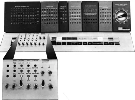
The operator's console includes control keys, switches, indicators, and an input/output typewriter. The control keys and switches are used for manual and/or automatic operation of the system. The indi-cators provide visual indication of the status of various registers, program indicators, and input/output units. The typewriter enables operator entry of data and instructions into core storage; it also provides a per-manent log of operator intervention during program operation. As an output unit, the typewriter provides operator-oriented messages of job progress and detail. Information is entered into the system via the following input units: 1621 Paper Tape Unit, 1622 Card Read-Punch, 1311 Disk Storage Drive, and the console typewriter. Maximum input speeds are:
1621-150 characters per second 1622 Model 1-250 cards per minute 1622 Model 2-500 cards per minute
1311-100 characters (one sector of data) per 2 ms. Seek time (the time required to move the read/write heads to the desired disk track) is 75 ms minimum, 250 ms average, and 392 ms maximum. This time is zero if the heads are already located at the proper disk track.
Console typewriter-operator's speed
The system provides output information via the 1622, the tape punch in the 1621, the console type-writer, the 1443 Printer, and the 1627 Plotter. (The 1621 and 1627 units cannot be installed on the same
system except by special order.) Maximum output speeds are:
1443 Model 1-430 lines per minute 1443 Model 2-600 lines per minute 1621-15 characters per second 1622 Model 1-125 cards per minute 1622 Model 2-250 cards per minute
1627 Model 1-18,000 steps per minute (11 inch horizontal plot)
1627 Model 2-12,000 steps per minute (2m~ inch horizontal plot)
Console typewriter-10 characters per second
The 1443 and 1622 units contain buffer storage
media, which enables CPU operation concurrent with
printing, card reading, and card punching. When printing and/or punching, the CPU transfers the out-put data from core storage to the 1443 print buffer and the 1622 punch buffer in 8.06 ms and 3.4 ms, respectively, and then continues program operation while the line is being printed and the card is being punched. Simultaneously, the data from a card in the 1622 read feed can be read into the read buffer. Following loading of the read buffer, the CPU transfers the card data to core storage and then continues proc-essing while the next card is being read into the read buffer. Thus, reading, punching, and printing can be done simultaneously.
The 1620 CPu (Figure 1) contains the arithmetic and
logic section of the system.
Data Representation
Data can be classified as digits, fields, or records, depending upon the operation in which the data is addressed.
Digits
BCD Bit Array. Each core storage position is ad-dressable and can store one digit of information in BCD fonn (C, F, 8, 4, 2, and 1). The bit positions of each digit consist of four numerical bits, one flag (F) bit, and one check (C) bit.
Check Flag
Bit Bit Numerical Bits
~--~---/
C F 8 4 2
The value of a decimal digit is the sum represented by the bits present in the 8, 4, 2, and 1 numeric bit positions. Only bit combinations whose sum is nine or less are used. A negative numeric expression has a sign flag in the units position of its field. Consider-ing only the numeric bit positions, the decimal 6 is
Figure 1. IBM 1620 Modell Central Processing Unit
1620 Central Processing Unit, Model 1
represented as 0110, the decimal 7 as 0111, etc., as shown in Figure 2.
Check Bit (C). Each digit position within the com-puter must contain an odd number of coded bits, in-cluding a flag bit, if there is one, for correct parity. To create this odd-bit number, a C bit is automatically added, when required, to each digit position as data enters core storage. Thereafter, during processing, a digit position with an even number of bits causes the machine to signal a parity error. A C bit alone repre-sents a plus zero.
Flag Bit (F). Depending on its location and the operation performed, the flag bit is used in five ways:
o
1
2
3 4 5
6
7 8 9
1. Sign Control
A numeric data field is negative if the units (low-order) digit contains a flag bit, and posi-tive if the units digit does not contain a Hag bit. Minus five is shown as
5;
plus five is shown as 5. The BCD representations for minus and plus five are F-4-1 and C-4-1, respectively.2. Field Mark
A flag bit as a field mark defines the leftmost (high-order) digit of a numeric data field. A field is shown as XXXX where the dash over the high-order digit is the field mark.
3. Carries
Flag bits present in certain digits of the Add table (Appendix B) are interpreted in arith-metic operations as carries. For example, an eight with a carry is shown as
8.
Flag bits are contained in table storage and transferred automatically, as required.4. Minus Zero
The F bit alone represents a minus zero (0).
C F 8 4 2
x
X X
X X X
X
X X X
X X X
X X X X
X X X
5. Indirect Addressing (Special Feature)
A flag bit over the units position of an instruc-tion address (P or Q) indicates an indirect ad-dress.
Record Mark (=f=). The record mark is a nondecimal machine digit coded C-8-2. It is used primarily in input/ output operations and in record transmission within the 1620; it cannot be used as a significant digit in an arithmetic or compare operation.
Group Mark ($). The group mark, coded C-8-4-2-1,
is used in disk storage operations to verify the correct length of records written on or read from disk storage. Numerical Blank. The numerical blank ( coded
C-8-4) is used for format control of blank columns in card punching, and cannot be used in arithmetic or
compare operations. The I/O instructions, Read
Nu-merically and Write NuNu-merically, further detail the use of the numerical blank.
Field
A field is composed of related digits that are treated as a unit of information (temperature, flow rate, etc.). The digits of a field are consecutively addressed. A field is addressed by its rightmost (low-order) digit which occupies the highest-numbered core storage position of the field. Fields are processed from right to left into successively lower-numbered core storage positions until a digit with a flag bit is sensed. The shortest admissible field consists of two digits: the addressed digit which mayor may not contain a flag (negative or positive) and the high-order digit con-taining the flag bit or field mark.
I - - F i e l d - - I
X X . • • • X
t
O;,ec,;o" P<oce ... d!
Flag Bit Addressed Digit (End of Field) (Low-Order Position of Field)
Record
A record consists of a field or fields of related data normally grouped for input/ output operations and internal data transmission. A record is addressed at the leftmost (high-order) digit which occupies the lowest-numbered core storage position of the record. Records are processed serially from left to right into successively higher-numbered core storage positions.
Output and internal record transmission are termi-nated when a record mark is sensed, except for card output which is terminated only after 80 columns are transferred to 1622 buffer storage.
A record is entered into core storage, starting at the addressed digit and continuing from left to right into successively higher-numbered core storage posi-tions, until terminated by an end-of-record signal from the input unit. The end-of-record signal from paper tape causes a record mark to be placed in core storage as the rightmost digit of the record. When input is from the typewriter, the Record Mark key must be depressed to place a record mark in core storage. When input is from punched cards, a record mark is automatically placed in core storage only when 0, 8, 2 are punched in a card column.
Record Mark Record Mark
~
_d _
XX+X • • • XX • • • XX X =+= X X
F i e l d F i e l d F i e l d
-- -- -- I I -- -- -- -- -- -- -- R e c o r d -- -- -- -- -- -- -- -- I
•
Arrows Indicate Direction of Processing
Magnetic Core Storage
A core storage module, which is 20,000 addressable positions of magnetic core storage, is located in the
1620. Two additional modules are available in the
IBM 1623, Models 1 or 2, to increase the total core
storage capacity of the 1620 System to 40,000 or
60,000 positions. Data and instructions in core storage are not affected by the manual turning on or off of power if care is taken to ensure that the 1620 System is in the manual mode before power is turned off.
Core Array
Each core storage module (20,000 positions) is made up of 12 core planes as shown in Figure 3. Each core plane contains all cores for. a specific bit value. The core planes are labeled C, F, 8, 4, 2, and 1. The even-address planes are· the top six planes, and the odd-address planes are the bottom six planes. An even address has an even number as its units digit, while an odd address has an odd-numbered units digit.
Bit Core Planes (Even)
C
F
8
4
2
Bit Core Planes (Odd) C
F
8
4
2
MBR-Even MBR-Odd
ION"Cores are shown solid black to indicate that they contain a bit.
Figure 3. 1620 Core Storage Readout
6
condition. If on, the core contains a bit; if not, it is said to be off.
Two-Character Transfer
During a core storage readout cycle, which takes 20
p.sec, the addressed core in each plane is read out, as illustrated by the vertical line in Figure 3. However, only cores that are on cause data to enter the 2-digit Memory Buffer Register (MBR) as bUs.
The function of the MBR is to. receive digits entering or leaving core storage. Digits leaving storage are
4
the even-digit planes. The 4 core is on in the odd-digit plane. Thus MBR-E and MBR-O contain 64.
Because all 12 core planes are affected, any single-core storage address affects two adjacent storage posi-tions: one with an odd-numbered address and one with an even-numbered address. Even-numbered ad-dresses affect the next higher position. If the digit at address 00500 (even) is addressed and program-med to be read from core storage, the digit at address 00501 is also read. Odd-numbered addresses affect the next lower position. Address 00501 (odd) also affects address 00500. The selection of the digit to be used is determined by the operation to be per-formed. The digit actually addressed is moved to the I-digit Memory Data Register.
Sequential Core Storage Addressing
Core storage positions are addressed sequentially from 00000 to the highest-numbered address of the core storage positions installed-19999, 39999, or 59999. Character transfer to, from, and within core storage embodies the c'wrap around" principle, i.e., the highest-numbered address is followed by the numbered address when incrementing and the lowest-numbered address is followed by the highest-num-bered address when decrementing. Thus, assuming a 20,000-position core storage capacity, the increment-ing sequence is 19998, 19999, 00000, 00001, etc.; and the decrementing sequence is 00001, 00000, 19999, 19998, etc.
Character Representation
The 1620 can be programmed to read and write numeric and alphameric data. The input! output in-struction (numeric or alphameric) determines wheth-er data is read and/or written numwheth-erically or alpha-merically.
Numerical Representation
One decimal digit is required in core storage to rep-resent a numerical character. No alphabetic or special characters except the record mark and numeric blank can be represented in the numeric mode.
Alphameric Representation
Two decimal digits are required in core storage to represent an alphameric character, i.e., an alphabetic character, a special character, or a numeric character. A 2-digit alphameric representation of numeric char-acters is provided to permit reading of mixed alpha-betic, special and numeric characters without changing from an alphameric to a numeric instruction.
Figure 3 shows the bit configuration of a <CU" if the 1620 is in the alphameric mode. The two alphameric digits of a character must occupy adjacent core stor-age positions, and the zone digit must occupy the even address. This storage requirement is satisfied by programming; alphameric read/write instructions must contain an odd-numbered P address. Figure 4 shows the zone and numeric digits that have been assigned to represent all the alphameric characters used in the 1620.
rr
zone Digit ,-Numerical Digit
+
r-Character00 b 03 04 ) 10 + 13 $
14 * 20
-21 /23 I
24 ( 33 = 34 @
41 A 42 B
43 C 44 D 45 E
46 F
47 G 48 H
49 I 50 0
51 J
52 K
53 L 54 M 55 N 56 0
57 P
58 Q
59 R 62 5
63 T 64 U 65 V 66 W
67 X
68 Y 69 Z
70 0 71 1 72 2 73 3 74 4 75 5 76 6
77 7 78 8 79 9
Stored Program Concept
The 1620 CPU is a stored program computer, that is, it stores and executes its instructions internally. The computer can perform distinct operations such as adding, subtracting, multiplying, comparing, branch-ing, and so on. It is directed by an instruction placed in core storage to perform a specific operation. The programmer can select the most suitable operations, from various computer operations, to solve a problem or process data. A group of instructions representing the operations to be performed is called a program. Once the program is placed in core storage, thE) computer can be directed to execute automatically the instructions composing the program. The program normally is executed in a sequential manner, that is, the computer starts with the first instruction and pro-gresses serially through the program, interpreting and executing each instruction. However, this sequence of operations can be altered by the use of instructions that may direct the computer to an instruction located somewhere other than the next sequential position.
Instruction
Characteristics
The 1620 uses a 12-digit machine language instruction divided into three parts: a 2-digit operation ( Op ) code, a 5-digit P address, and a 5-digit
Q
address. An instruction as it appears in core storage may be divid-ed into 0, P, and Q subscripted numbers, as follows:In contrast to a data field, which is addressed at its rightmost (low-order) digit and read from right to left, instructions are addressed at 0o, the leftmost
(high-order) digit, and read from left to right.
Op Code
Upon initiation of an instruction, the Op code is placed in a 2-digit Op register and is analyzed to
1620 Instructions
determine the operation to be performed. The address of an instruction must always be even, i.e., the 00 digit of an operation code must be stored in an even-numbered address so that the Op register can receive both digits.
P Address
The P address specifies: (1) the location to which data is transmitted, (2) the location to which the program branches, (3) the location from which data is transmitted (output instructions), or (4) the loca-tion of the alphameric field in the Transfer Numerical Strip and Transfer Numerical Fill special feature in-structions.
QAddress
The
Q
address specifies: (1) the location from which data is transmitted, (2) the indicator being interro-gated, (3) the input/output device being used, or ( 4) the location of the numeric field in the Transfer Numerical Strip and Transfer Numerical Fill special feature instructions. Also, instruction modifier digits are placed in the Q address for those instructions with the same Op code number.Instruction Execution Time
Each instruction or operation performed by the com-puter is divided into two parts: I (Instruction) cycle and E (Execution) cycle.
INSTRUCTION CYCLE
During the I -cycle, an instruction is read from core storage and interpreted; control circuitry is established. The I-cycle always takes eight 20-microsecond machine cycles (160 microseconds).
EXECUTION CYCLE
The operation specified by the instruction is carried out during the E-cycle. The number of machine cycles necessary to execute an instruction depends on the operation, size of the data fields, and signs of the fields (in arithmetic operations). The last E-cyde of an instruction is followed by the first I -cycle of the next instruction.
Appendix A. The symbols used in the formulas are defined as follows:
Dp Number of digits, including high-order zeros, in the field at the P address. Dq Number of digits, including high-order
zeros, in the field at the
Q
address. D q' Number of digits, including high-orderzeros, in the data field of an immediate instruction.
Dz Number of positions compared, prior to the detection of a digit other than zero. T Time in microseconds ( {J-sec ) or
milli-seconds (ms), as noted.
Additional symbols used only in Load Dividend, Load Dividend Immediate, Divide, and Divide Immediate instructions are defined under Execution Time, follow-ing the explanation of the individual instruction.
Immediate Instructions
Certain arithmetic, internal data transmissions, com-pare, and branch instructions are labeled "immediate." Immediate instructions use the digits in the Q7, Qs, Q9, QlO and Ql1 positions of the instruc,:tiOn as data instead of as a core storage address. .
Thus, the
Q
data is located immediately within the instruction. For example, when the Transmit Field Immediate instruction, 16 00543 18765, is executed, the Q part of the instruction, 18765, is transmitted to the P address (Figure 5). Data transfer begins at Ql1of the instruction, and continues until a flag bit is found, Q7 in this case. If the flag bit was at QI0,
65
would be transferred to 00543. The difference be-tween the Transmit Field and Transmit Field Imme-diate instructions can best be shown by comparing Figures 5 and 6. The Transmit Field instruction, Figure 6, tranfers the data at the Q address to the P addresses.OP
Code P Address Q Address
1116101015141311/81716151
I I I
---~
Core Storage
Figure 5. Transmit Field Immediate - Data Flow
OP
Code P Address Q Address
121610101514131118171615\
I~I~
Core Storage
~
~&
294
~
I
The Indirect Addressing special feature saves pro-gram steps and computer time by providing a direct
method of address modification. Its primary use is in programs where multiple instructions have the same address, and this address is to be modified by the program. Indirect Addressing may also be used for linking subroutines~
Description
Normally, the P or
Q
address of an instruction is the location of the data used during execution of the instruction. An indirect address, however, is the address of a second address instead of the address of data. This "second address" is the core storage ad-' dress of the data to be used unless the second address is yet another indirect address. In effect, the address at the indirect address location is a subsitute for the address of the instruction.The data field specified by the indirect address is always five digits in length. The upper digit of the address does not require a flag bit to define the field.
Indirect Addressing
Moreover, its length is always five digits, even though flag bits exist within the field.
The P or Q address of an instruction is indirect when a flag bit is over the units position. Figure 7 shows that (1) the instruction (21 00500 00650) has an indirect P address of 00500, (2) the data at 00500 is 00780, which is used as the P address during execu-tion of the instrucexecu-tion, and ( 3 ) the instrucexecu-tion
(21 00500 00650) is not altered in core storage; only the instruction register of the 1620 is changed.
The data at the location specified by the indirect address is also an indirect address if a flag bit exists in the units position. This chaining effect continues until a flag bit does not exist in the units position of the address. The address is then treated as a direct address.
Any P or Q address of an instruction that specifies the location Of data can be an indirect address. See Table 1 in the next section of this manual. When the P address of an immediate inst:t:uction is an indirect address, the Q data cannot be more than six digits in
CORE STORAGE
( 1) Instruction with Indirect P Address
(2) The data (00780) at the indirect address is substituted as the new P address in the instruction.
(3) The resultant instruction is executed normally with the New P Address.
Figure 7. Indirect Addressing Data Flow
OP
.~
length because the flag bit over the units position of the P address also defines the end of the immediate data.
Execution Time.
Each address interpreted as an indirect address requires four additional 20-ftsec mem-ory cycles. For example, an instruction with two indirect addresses requires an additional 160 ftsec.Examples
The Add instruction, 21 00500 00650, is shown in Figure 8 with both direct and indirect
Q
addresses. Line 1 shows direct addressing; the Q data is obtained from the Q address. Line 2 shows the Q address as indirect; the Q data is obtained from the addressspecified by the indirect address. Line 3 shows that the address specified by the indirect address is also indirect; the
Q
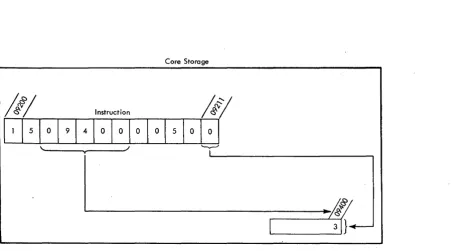
data is obtained from the address specified by the second indirect address.The data flow diagram for an Add Immediate in-struction, 11 00500 00650, is shown in Figure 9. The Q data 000650, is added to the data at the address specified by the indirect P address. The result, 1155078, replaces the original P data, 1154428, at 09400.
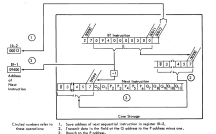
A data flow diagram for a Branch instruction is shown in Figure 10. The first five digits at that in-direct address are the address to which the computer branches for its next instruction.
Instructions Data at Storage Locations Resultant Modified Actual Q Actual Q
00650 1 5225 12500
0)2 1 00500 00650 1 5225
@21 00500 00650 15225 12500
@21 00500 00650 15225 12500 12345
Figure 8. Examples of Indirect Addressing
OP Code
Dr:
pT
Q~
500': 00650~
I, IY I
I
I
II
& 10 9400i
2 1
(0)2 1
(b) 2 1
{6 Digits Maximum}
00065 1 15442 1 15507 0 8 8
Figure 9, Indirect Addressing, Add Immediate Instruction
Instruction Address Data Used Used
00650 15225
00500 15225 1 5225 125.00
00500 15225
00500 12500 12500 12345
CORE STORAGE
\:)/.
~Af}
IT
1 54428~
L
Add149100500100000
I
'---v--J
The OP code for the new instruction is contained in core storage locations
16000 and 16001.
Figure 10. Indirect Addressing, Branch Instruction
CORE STORAGE
Instruction Types
All 1620 instructions fall into six general categories according to function:
1. Arithmetic 2. Compare 3. Branch
4. Internal Data Transmission 5. Input/Output
6. Program Control
The Divide and Floating-Point instructions are 1620 Model 1 special features and must be ordered as such for inclusion in the 1620 Model 1 repertoire of in-structions-Move Flag, Transfer Numerical Fill, and Transfer Numerical Strip.
Table 1. 1620 Instructions
I nstruct ions Arithmetic
Add Add (1) Subtract Subtract (1)
Multiply Multiply (I)
Load Dividend* Load Dividend (1)* Divide*
Divide (1)* Floating Add* Floating Subtract* Floating Multiply* Floating Divide* Compare
Compare Compare (I)
Branch Branch Branch No Flag Branch No Record Mark Branch No Group Mark * Branch on Digit Bronch Indicator Branch No Indicator Branch and Transmit Branch and Transmit (I)
Branch Back Branch and Transmit
Floating* * Speci a I Feature
(I) Immediate
Mnemonic A AM S SM M MM LD LDM 0 OM FADD FSUB FMUL FDIV C CM B BNF BNR BNG BD BI BNI BT BTM BB BTFL
Code P&Q P
21 X
11 X
22 X
12 X
23 X
13 X
28 X
18 X
29 X
19 X
01 X
02 X
03 X
09 X
24 X
14 X
49 X
44 X
45 X
55 X
43 X
46 X
47 X
27 X
17 X
42
07 X
All 1620 instructions with their associated Op codes, mnemonics, modifier' digits, and allowable indirect addresses are shown in Table 1. Modifier digits are those required in Qs, QI), and Qll to differentiate be-tween instructions having the same Op codes.
Arithmetic Instructions
Data flow, field length definition, indicator control, and sign analysis are common to all 1620 Arithmetic instructions, and are therefore explained before the actual instructions.
Instructions Mnemonic Code P&Q P
Internal Data Transmission
Transmit Digit TO 25 X
Transmit Digit (I) TOM 15 X
Transmit Field TF 26 X
Transmit Field (I) TFM 16 X
Transmit Record TR 31 X
Transfer Numerical Strip* TNS 72 X
Transfer Numerical Fill* TNF 73 X
Floating Shift Right* FSR 08 X
Floating Shift Left* FSL 05 X
Transmit Floating* TFL 06 X
Input/Output
Read Numerically RN 36 X
Write Numerically WN 38 X
Dump Numerically ON 35 X
Read Alphamerically RA 37 X
Write Alphamerically WA 39 X
Seek* K 34 X
Program Control
Control K 34
Set Flag SF 32 X
Clear Flag CF 33 X
Mave Flag* MF 71 X
Halt H 48
Data Flow and Field Length Definition
Data is read serially from right to left (low-order to high-order) until terminated by a flag bit defining the high-order position of the field. For example, where the data in a field is 285, the dash (flag bit) over the high-order digit indicates a field mark. The Program Testing section of this manual provides more specific data flow information.
The minimum length of both the P and Q fields is two digits: a units digit which contains the sign, and at least one higher-order digit which is needed for field definition.
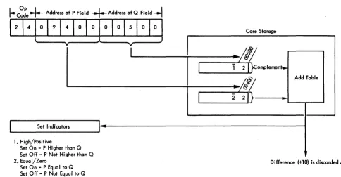
Arithmetic Indicators
Three arithmetic indicators and their associated con-sole lights are controlled by Arithmetic instructions and turned off by the Reset key on the 1620 console.
High/Positive. The High/Positive (H/P) indicator is turned on at the beginning of each Arithmetic in-struction and remains on if the result is positive and not zero. It is turned off if the result is negative or zero.
Equal/Zero. The Equal/Zero (E/Z ) indicatO'r is turned on at the beginning of each Arithmetic instruc-tion and remains on if the result is zero. It is turned off if the result is not zero.
Arithmetic Overflow (O'flow). The Arithmetic
Check indicator is turned on during the execution of Add, Subtract, and Compare instructions, if either of the following conditions exists:
1. The number of digits in the
Q
data exceeds the number of digits in the P data. Only the number of digits in the Q data that equal the number of digits in the P data are used in de-veloping the result.2. The result causes a carry beyond the high-order position of the initial field at P. (The carry is lost.)
This indicator is also turned on during a Divide operation if more than nine successful subtractions occur (ten or more subtractions indicate the divisor is mispositioned) .
The Arithmetic Check indicator is turned off by the execution of a Branch Indicator or Branch No Indicator instruction, or by m'anual pressing of the Reset key, and does not automatically turn on at the beginning of each Arithmetic instruction.
Table Look-up
A unique method of doing arithmetic calculations is used in the 1620. Two tables (Multiply and Add),
stored in the "table area" of core storage, are auto-matically referred to by the computer during arith-metic operations. The positions of core storage con-taining the table data are addressable but must not be altered; altering can cause incorrect arithmetic operations to result.
Three hundred positions of core storage have been assigned to the Table area. Two hundred positions,
00100 through 00299, are assigned to the storage of the Multiply table. One hundred positions, 00300
through 00399, are assigned to the storage of the Add table used in all arithmetic operations. (See Appen-dix B.) A digit with a flag bit in the table indicates that a carry is associated with that digit.
In addition, 20 positions, 00080 through 00099, are used to receive the product or partial product in Multiply operations.
Sign Analysis
Addition and Subtraction. The data in the Q field is either true-added or complement-added to the data in the P field. A true-add operation causes the Q data to be added just as it is. A complement-add operation causes the Q data to be altered before addition, as follows: the units digit is tens-complemented and the remaining higher-order digits are nines-complemented
(95 becomes 05, 139 becomes 861, 2476 becomes
7524, etc.). The sign analysis chart in Figure 11 shows that (1) the Q data is complement-added dur-ing addition and subtraction when the signs of the P and Q fields are different and alike respectively,
( 2) if the
Q
field is complemented and if the value of the originalQ
data is higher than the value of the P data, the sum or difference is recomplemented, and (3) if a recomplement occurs, the original sign of the P field is changed.For example:
Add
+15
(Q data) to-35
(P data). According to the sign control analysis chart1. The Q data is complement-added
(15
becomes85 ),
and85
+
35
==
'2[
The hundreds carry is lost. A carry is always lost when it causes the sum or difference to exceed the size of the P field. Arithmetic Check is not turned on since the carry in this case indicates that recomple-menting the P field is not required.2. The sum is not recomplemented (15 is less than 35).
ADD
Sign of P Field + +
-Sign of Q Field +
-
+True or Complement Add Q Field True Comp Comp Recomplement only if value of , , ,
2
Q Field is greater than value of
,-!
P Field ,
, " ,
3 Change P ~ield sign only if
-
+recomplement occurs (changed si gn shown).
Figure 11. Sign Control Chart
Multiplication and Division. The sign of each prod-uct and quotient is determined algebraically from the signs of its factors, as follows:
+a x +b +c
-a x +b -c
-a x -b +c
+a +b +c
-a +b -c
-a -b +c, etc.
Add (A-21)
Description. The data in the field at the
Q
address is added to the data in the field at the P address and the sum replaces the P field data. TheQ
field data remains unchanged.In Figure 12, the sum (14) is "looked up" in the Add table and replaces the 12 at 00500 (P address). The field mark remains at the high-order position. When the sum is zero, the sign of the P field is
re-Op Code
I---
Address of P Field+
Address of Q Field--l
Q Value at 09400 =
02
P Value at 00500::
12
Sum at P ..
14
(replaces original value)Figure 12. Add Instructions - Data Flow
,
l
I I
:
l
SUBTRACT
-
+ + --- + - +
-True Comp True True Comp
,
~
I
I
,
,
, :
I
- +
tained. For sums other than zero, the sign of the field with the larger value is retained. High-order zeros are supplied if the number of signiRcant digits in the Q field is less than the number of signiRcant digits in the initial field at P.
The H/P indicator is on if the sum is positive and not zero; the E/Z indicator is on if the sum is zero. Neither indicator is on if the sum is negative.
Execution Time. Execution time varies according to the number of digits (high-order zeros included) in the ReId at P and according to whether recomple-menting is necessary. Recomplement time must be added to the basic time when the signs of the Relds at the Q and P addresses are different initially and the absolute numeric value of the
Q
field is greater than the absolute numeric value of the P field.Basic Execution Time: T
==
160 + 80Dp f-LsecRecomplement Time: T
==
80Dp f-LsecCore Storage
~/Il
o
2f}--... -,
<~
Add Tablel~~D---"'''~'
Add Immediate (AM-ll)
Description. The description is the same as that for Add (A-21) except that the data in the
Q
part of the instruction is used as the Q data. For example, if the Op core were 11 in Figure 12, theQ
data would be 09400 and the result would be 12 (00+
12). The three high-order positions of the Q data (094) are not used because the P-data flag bit (above the one in 12) stops the add operation. The Arithmetic Checki~dicator is turned on because the
Q
data field (09400) exceed the two digits of data (12) contained in the field defined by the P address (00500).Execution Time. Same as Add.
Subtract (5-22)
Description. The data in the field at the
Q
address is subtracted from the data in the field at the P address and the difference replaces the data in the field at the
P
address. The data in the field at theQ
address remains unchanged.
The data in the field at the Q address is comple-mented if it has the same sign as the data in the field at the P address.
A zero result retains the sign of the field at the P address. The sign of a result, other than zero, is
determined by algebraic analysis of the P and Q
fields. High-order zeros are supplied if the number of significant digits in the Q field is less than the number of significant digits in the initial field at the P address.
I
Address ofI
Address ofI
Op Coder----
Multiplicand • • Multiplier----1
Multiplicand Value
=
12
Multiplier Value = 02Product Value
=
0024Figure 13. Multiply Instruction - Data Flow
The H/P indicator is on it the difference is positive and not zero; the E/Z indicator is on if the difference is zero. Neither indicator is on if the difference is negative.
Execution Time. Execution time is computed by using the Add instruction formula. Recomplement time is added to basic time when the signs of the fields at the Q and P addresses are the same initially and the absolute numeric value of the field at the
Q
address is greater than the absolute numeric value of the field at the P address.
Subtract Immediate (SM-12)
Description. The description is the same as for Subtract (S-22) except that the digits in the
Q
part of the instruction are used as theQ
data.Execution Time. Same as Subtract.
Multiply (M-23)
Description. The data in the field at the P address is multiplied by the data in the field at the
Q
address, and the result (product) is placed in core storage, beginning at position 00099 and extending through successively lower-numbered positions. The data in the fields at the Q and P addresses is not changed by the operation.In Figure 13, the multiplicand (12) at 00500 is multiplied by the multiplier (02) at 09400. The prod-uct (0024) is developed and stored at 00096-00099.
Core Storage
Product Area
The 20 digits of the area in core storage specified as the "product area" (positions 00080 through 00099) are automatically cleared to zeros before multiplica-tion begins. Formamultiplica-tion of the product then proceeds serially from right to left until terminated by the flag bit marking the high-order position of the field at the
Q
address. A flag bit is stored in the high-order position of the product, and the sign of the product is indicated by the presence (negative) or absence (positive) of a flag bit in position 00099. A zero prod-uct may have a negative or positive sign, depending upon the signs of the fields at theQ
and P addresses. The number of digits in the product is equal to the sum of the digits (high-order zeros included) in the fields at theQ
and P addresses. The size of the product is limited only by the core storage positions available. A product longer than the 20 positions of the product area may be formed, but positions in excess of 20 digits must be cleared to zeros by pro-gram instructions preceding the Multiply instruction.It is possible to develop a product so large that it extends from its units position (location 00099),
left-ward to location 00000, continues at the highest-order core storage location (19999, 39999, or 59999), and finally terminates with its high-order digit at some location lower than the highest-order location. The Arithmetic Check indicator is not turned on when the product exceeds 20 digits in length. The H/P indicator is on if the product is positive and not zero; the E/Z indicator is on if the product is zero. Neither indicator is on if the product is negative.
Execution Time. The execution time varies accord-ing to the number of digits in the fields at the
Q
and P addresses.T
==
560+
40Dq+
168 DqDp fJ-secMultiply Immediate (MM-13)
Description. The description for Multiply (M -23 ) applies except that the data in the
Q
part of the in-struction is used in place of the data in the field at theQ
address.Execution Time. T
==
560+
40D/+
168Dq'DpThe Automatic Division special feature simplifies programming and increases the processing speed of division problems by two to four times that of pro-grammed routines. Only one command need be given. Four commands are provided, however, to facilitate positioning of the dividend and divisor in core stor-age. There are no practical limitations placed upon the size of the dividend. divisor, or quotient.
A quotient and remainder of 20 digits are devel-oped in the product area (00080-00099). When the quotient plus the remainder exceeds 20 digits, core storage positions lower than 00080 ( 00079, 00078, etc.) must be reset to zeros by programming. One additional position should also be cleared to allow for a possible overdraw. For example, if 25 positions ary required for the quotient and remainder, 00074-00079 would have to be reset to zeros before the divide command was given.
The four instructions provided with the Divide feature are:
Load Dividend (LD-28)
Load Dividend Immediate (LDM-18) Divide (D-29)
Divide Immediate (DM-19)
The formula for computing the total execution time follows the description of each instruction.
Data at Core
Instruction Storage Address Description
00650
(1) 28 00096 00650 21365 Load Dividend
(2) 28 00099 00650 01234 Load Dividend
(3) 18 00098 00650 56789 Load Dividend Immediate
Figure 14. Load Dividend Instructions
Automatic Division
Load Dividend (LD-281
Description. The dividend must be stored in the product area before a Divide command is given. The Load Dividend instruction may be used to satisfy this requirement.
The product area (00080-00099) is automatically reset to zeros. The dividend (Q address) is transmit-ted to the product area (P address), beginning at the low-order dividend digit and terminating at the flag bit marking the high-order· position of the dividend field. The P address is 00099 minus the number of zero positions desired to the right of the dividend.
The algabraic sign of the dividend is automatically placed in location 00099 regardless of where the low-order dividend digit is placed by the P address. A flag bit automatically marks the high-order digit of the dividend.
Example: Two Load Dividend instructions and one Load Dividend Immediate instruction are shown in Figure 14.
0
00
0 0 0
0
0
0
1. The Load Dividend instruction, , 28 00096 00650
causes the low-order position of the dividend to be placed at 00096. The sign (minus) is stored at 00099.
~ N N C") "<t l() -.0 r--.. 00
0-00 0-00 0- 0- 0- 0-0 0
·
...
0 0 0 0 0 0 0 00 0 0 0 0 0 0 0 0 0
o 0 0 0 0 0 0 0 0 0
0 0
·
...
2 1 3 6 5o
0 00 0
·
...
0 0 0 0 1 2 3 42. The Load Dividend instruction,
28 00099 00650,
causes the low-order position of the dividend to be placed at 00099. The sign (plus) is stored at 00099.
3. The Load Dividend Immediate instruction,
18 00098 00650,
causes the low-order position of the dividend (the Q part of the instruction) to be placed in the field beginning at 00098. The sign (plus) is stored at 00099.
Execution Time. T
==
400 +40Dn fLsec, whereDn equals the number of digits in the dividend.
Load Dividend Immediate (LDM-l 8)
Description. The description for Load Dividend applies except that the data in the Q part of the instruction is transmitted to the P address.
Execution Time. Same as a Load Dividend (LD-28).
Divide (0-29)
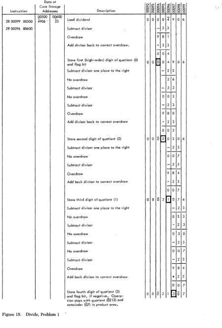
Description. The divisor (Q address) is successive-ly subtracted from the dividend. The P address of the Divide instruction positions the divisor for the first subtraction from the high-order positions of the divi-dend, as in manual division. The P address is deter-mined by subtracting the number of digits in the quotient from 100.
Examples: Problem 1: 4906
+-
23==
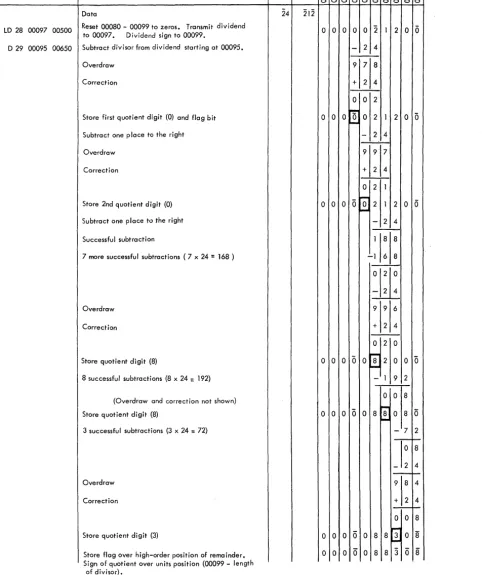
0213 and a remainder of 07. Figure 15 shows the manner in which the 1620 solves this problem.Problem 2: -212 (212)
+-
24
==
-8.83 (00883) anda remainder of
08.
Figure 16 shows how the 1620solves this problem.
As illustrated in these examples, each subtraction without overdraw causes the quotient digit to be increased by 1. Quotient digits are developed in the units position of the Multiplier/Quotient register. An overdraw initiates a correction cycle (the divisor is added once), and the next subtraction occurs one place to the right.
The first (high-order) quotient digit is stored at the address equal to the P address of the Divide in-struction minus the length of the divisor. A Hag bit is generated and stored with the first quotient digit. Subsequent quotient digits are stored to the right of the last-stored quotient digit. Division is terminated
after the last quotient digit is developed by sub-tractions with the units position of the divisor at 00099.
The quotient and remainder replace the dividend in the product area. The address of the quotient is 00099 minus the length of the divisor. The algebraic sign of the quotient (determined by the sign of the dividend and divisor) is automatically placed in the low-order position of the quotient. The address of the remainder is 00099. A Hag bit is automatically placed in the high-order position. The remainder has the sign of the dividend and the same number of digits as the divisor.
The H/P indicator is on if the quotient is positive
and not zero; the E/Z is on if the quotient is zero. N either indicator is on if the quotient is negative. The quotient must be at least two digits in length; one position is required for the sign and one for the field mark (Hag bit).
Execution Time. T
==
160+
520DvQt+
740 QtfLsec. Dv and Qt equal the number of digits in the
divisor and quotient, respectively. The formula as-sumes an average quotient digit of 4.5. If a Load Dividend or Load Dividend Immediate instruction is used, the divide operation execution time may be considered as the total time for both the Load Divi-dend and Divide instructions.
T
==
560+
40Dn + 520DvQt+
740Qt fLsecDivide Immediate CDM-19J
Description. The description of Divide (D-29) ap-plies except that the data in the Q part of the in-struction is used as the divisor.
Execution Time. Same as Divide (D-29).
Decimal Point Location
Data at Core Storage Instruction Addresses
00500 00600 2800099 00500 4906 " 23
2900096 00600
Figure 15. Divide, Problem 1
Description Load dividend
Subtract divisor Overdraw
Add divisor back to correct overdraw.
Store first (high-order) digit of quotient (0)
and flag bit
Subtract divisor one place to the right No overdraw
Subtract divisor No overdraw Subtract divisor Overdraw
Add divisor back to correct overdraw
Store second digit of quotient (2)
Subtract divisor one place to the right No overdraw
Subtract divisor Overdraw
Add back divisor to correct overdraw
Store third digit of quotient (1) Subtract divisor one place to the right No overdraw
Subt.ract divisor No overdraw Subtract divisor No overdraw Subtract divisor Overdraw
Add back divisor to correct overdraw
Store fourth digit of quotient (3) Opera-and flag bit, if negative~ tlon stops with quotient (0213) and remainder (07) in product area.
N ~
0-0 0 0 0 0 0
0 0
0 0
0 0
0 0
0 0
~ I.() -0
'"
co 0-0- 0- 0- 0- 0- 0-0 0 0 0 0 0 0 0 0 0 0 0 0 0 0 0 0 00 0 4' 9 o -6
-
2 3~
+ 2 3 ---0 0 4~
0 0 4 9 0 6
-
-
2 3-T
- 2 3IF
- 2 3~
+ 2 3 0 0 3_
...
0 2 0
...
3 0 6-
2 3'j1
- 2 31k
+ 2 3 0 0 7~
0 2
...
1a
7 6-
2 3±t1
- 2 3To
- 2 3
~
- 2 39 8 4 + 2 3 1 - -
-;.-0 -;.-0 7
[image:23.620.70.521.65.730.2]Instruction
LD 28 00097 00500 D 29 00095 00650
Description Data
Reset 00080 - 00099 to zeros. Transmit dividend to 00097. Dividend sign to 00099.
Subtract divisor from dividend starting at 00095. Overdraw
Correction
Store first quotient digit (0) and flag bit Subtract one place to the right Overdraw
Correction
Store 2nd quotient digit (0) Subtract one place to the right Successful subtraction
7 more successful subtractions (7 x 24 = 168 )
Overdraw Correction
Store quotient digit (8)
8 successful subtractions (8 x 24 = 192)
(Overdraw and correction not shown) Store quotient digit (8)
3 successful subtractions (3 x 24 = 72)
Overdraw Correction
Store quotient digit (3)
Store flag over high-order position of remainder. Sign of quotient over units position (00099 - length
of divisor).
Figure 16. Divide, Problem 2
~O:~~~~~\):g§
00650 00500
§ § § §
8
§ § §
8 00 0 0 0 0 2 1 2 0 6
- 2 4
-;--1
7
1
8
+ 2 4
0 0 2
000~021200
J,o..,j - 2 49 9 7
+ 2 4
o
2 1o
0 0 0 ~...
2 1 2 0 0- 2 4
118 8 -1 6 8
01,2210 0
f t
9 9 6 + 2 4
0 2 0 0 0 0 0 0 r a 2 0 0 0
r--o - 1 9 2
0 0 8
0 0 0 0 0 8 r a ' 0 8 0
"""'"
- 7 2~IO;
- 2 4
':1::
0 0 8 0 0 0 0 0 8 8 2 : 0 8 [image:24.620.46.528.88.663.2]Incorrect
D;v;sor
Pos;t;on;ng
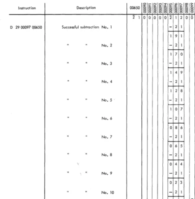
The following error conditions are caused by an in-correct P address in the Divide instruction:
Overflow. As illustrated in Figure 17, an incorrectly positioned divisor can cause more than nine success-ful subtractions and an incorrect quotient. The divide operation is terminated, the Arithmetic Check indi-cator and light are turned on, but processing does not stop unless the Overflow Check switch is set to STOP. Note the absence of a field-length flag in posi-tion 00095 when division is terminated. The flag is not placed automatically because the first quotient digit, which normally causes the flag bit to be gener-ated and stored, is not achieved.
If, after a division overflow, the field remaining in the product area is to be used for further operations,
I nstruct ion Description
D 29 00097.00650 Successful subtraction No.1
" " No.2
" " No. 3
" " No.4
" " No.5·
" " No.6
" " No.7
" " No.8
'.
" " No.9
11
" No. 10
Figure 17. Divide Overflow
the program must provide for a flag to be set in the desired position.
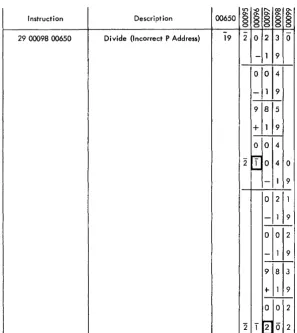
Loss of One or More High-Order Digits of the Dividend. The high-order digit of the dividend is assumed by the 1620 to be one position to the left of the high-order digit of the divisor. Figure 18 shows how the high-order digits of the dividend are lost if the di"isor is positioned too far to the right. Proc-essing continues with no indication of an incorrect quotient.
I ncorrect Termination. If the P address is less than 10000, i.e., between 00100 and 09999, the divide op-eration will terminate when a subtraction occurs at OXX99. This, in effect, restricts the size of the divi-dend to 10,020 digits, if only 20,000 positions of core storage are installed.
0 - " 1 M ~I.t') -or-.... coO-00650 0-0-0 0 0 0 0 0 0 0 0 0 0-0- 0-0- 0-0- 0-
0-0 0-0 0-0 0-0 0-0 0-0 0-0 0-0 0-0 0-0 0 0 0 0 0 0 0 0 0 0
2 1 0 0 0 0 0 2 1 2 0 0
-
2 1 1 9 1-
2 11 7 0
-
2 11 4 9
-
2 11 2 8
-
2 1 1 0 7-
2 10 8 6
- 2 1
0 6 5
-
2 1 0 4 4-
2 10 2 3
-
2 1 [image:25.618.54.444.302.700.2]§
-0 ~ ~0-§
0-Instruction Description 00650
§ § §
0
-29 00098 00650 Divide {Incorrect P Address} 19 2 0 2 3 0
- 1 9 0 0 4
-
1 9-9 8 5
+
1 9-0 0 4 -~
Figure 18. Division Error, Incorrect Programming
Summary of
Automatic Division Rules
1. Decimal point location: the number of divi-dend decimal digits minus the number of divisor decimal digits equals the number of quotient decimal digits (decimal digits are those digits to the right of the assumed deci-mal point).
2. Dividend position (P address of LD instruc-tion): determined by the number of quotient digits desired. An anaylsis of the problem and its relationship to these rules is necessary. 3. First subtraction (P address of divide ins
truc-2
2
1 0 4 0
II--- 1 9
0 2 1 - 1 9
-0 0 2
-
1 9-9 8 3
+- 1 9
-0 -0 2
-,....,
01 2
~
2
tion): 00100 minus the length of the quotient (the minimum length of the quotient is gen-erally the length of the dividend).
4. Quotient length: 100 minus the P address (minimum of 2).
5. Quotient address: 00099 minus the length of the divisor.
6. Remainder length: same as divisor length. 7. Remainder address: 00099 ( assuming
divi-dend at 00099).
-8. Sign of quotient: determined by algebraic signs of dividend and divisor.
[image:26.617.42.340.67.400.2]This special feature provides the 1620 with the ability to do floating-point' arithmetic, using floating-point instructions instead of program sub-routines.
The use of automatic floating-point operations can result in a 50 to 100 per cent increase in the
com-puting power of the 1620 CPU, depending on the
amount of floating-point computations required. Also, up to 15 per cent of the basic 1620 core-storage capacity can be saved through the elimination of subroutines and call sequence instructions associated with Floating Add, Floating Subtract, Floating Mul-tiply, and Floating Divide.
The Automatic Division special feature is a pre-requisite to the installation of Automatic Floating Point Operations.
floating-Point Arithmetic
Scientific and engineering computations frequently involve lengthy and complex calculations in which it is necessary to manipulate numbers that may vary Widely in magnitude. To obtain a meaningful answer, problems of this type usually require that as many significant digits as possible be retained during cal-culation and that the decimal point always be prop-erly located. When applying such problems to a computer, several factors must be taken into con-sideration, the most important of which is decimal point location.
Generally speaking, a computer does not recognize the decimal point present in any quantity used during the calculation. Thus, a product of 414154 will re-sult regardless of whether the factors are 9.37 x 44.2, 93.7 x .442, or 937 x 4.42, etc. It is the programmer's responsibility to be cognizant· of the decimal point location during and after the calculation and to ar-range the program accordingly. In a floating-add operation, for example, the decimal point of all num-bers must be lined up to obtain the correct sum. To facilitate this arrangement, the programmer must shift the quantities as they are added. In the manip-ulation of numbers that vary greatly in magnitude, the resulting quantity could conceivably exceed al-lowable working limits.
The processing of numbers expressed in ordinary form, e.g., 427.93456, 0.0009762, 5382, -623.147, 3.1415927, etc., can be accomplished on a computer only by extensive anaylsis to determine the size and
Automatic Floating-Point Operations
range of intermediate and final results. This anaylsis and subsequent number scaling frequently takes longer than does the actual calculation. Furthermore, number scaling requires complete and accurate in-formation as to the boundaries of all numbers that come into the computation (input, intermediate, out-put). Since it is not always possible to predict the size of all numbers in a given calculation, anaylsis and number scaling are sometimes impractical.
To alleviate this programming problem, a system must be employed in which information regarding the magnitude of all numbers accompanies the quan-tities in the calculation. Thus, if all numbers are represented in some standard, predetermined for-mat which instructs the computer in an orderly and simple fashion as to the location of the decimal pOint, and if this representation is acceptable to the routine doing the calculation, then quantities which range from minute fractions having many decimal places to large whole numbers having many integer places can be handled. The arithmetic system most com-monly used, in which all numbers are expressed in a format having the above feature, is called-. "floating-point arithmetic."
The notation used in floating-point arithmetic is basically an adaptation of the scientific notation widely used today. In scientific work,. very large or very small numbers are expressed as a number, be-tween one and ten, times a power of ten. Thus
427.93456 is written as 4.2793456 x 10² and
0.0009762 as 9.762 x 10⁻⁴• In the 1620 floating-pOint
arithmetic system, the range of numbers is modified to extend between .1 and .99999999; that is, the deci-mal point of all numbers is placed to the left of the high-order (leftmost) nonzero digit. Hence, all quan-tities may be thought of as a decimal fraction times a power of ten (e.g., 427.93456 as .42793456 x 103
1620 Automatic Floating-Point Operations
In 1620 Automatic Floating-Point Operations, a floating-point number is a field consisting of a var-iable length mantissa and a 2-digit exponent. The exponent is in the two low-order positions of the field, and the mantissa is in the remaining high-order posi-tions, as shown:
M,
MEEThe mantissa must have a minimum of two digits
and ca~ have a maximum of 100 digits. However,
when two fields are operands (quantities being added, subtracted, multiplied, divided), they must have man-tissas of the same length. The extremity of the field is marked by a flag over the high-order digit.
The exponent is established on the premise that the mantissa is less than 1.0 and equal to or greater than 0.1. The exponent is always two digits and has a range of -99 to +99. The length of the ex-ponent field is defined by a flag over the high-order
( tens) digit.
The mantissa and the exponent each have an al-gebraic sign represented by the presence (negative) or absence (positive) of a flag over the units position. A floating-point number with a negative mantissa and a negative exponent is represented as follows:
M .... MEE
Sign contro