2017 2nd International Conference on Computer Engineering, Information Science and Internet Technology (CII 2017) ISBN: 978-1-60595-504-9
An Optimized Interpolation Algorithm for Bayer
Pattern CFA Images based on Gradient
JIE XIAO, GUOZHENG YAN, ZHIWU WANG and YONGBING WANG
ABSTRACT
Digital cameras acquire images by using color filter array, each pixel contains information of only one color channel. In order to get the rest color channel information, interpolation of the image is needed. The interpolation algorithm directly affects the image quality, and most of the current algorithms have defects in some way. Some interpolation algorithms are very simple, thus causing image distortion, some perform well but are too complex to implement. This paper proposes an improved interpolation algorithm for the most widely used color filter array, Bayer array. The proposed algorithm can achieve both interpolation efficiency and interpolation effect. Based on bilinear interpolation algorithm and edge oriented interpolation algorithm, applying gradient method and color difference rule, the proposed algorithm makes full use of the correlation between color channels, and the algorithm doesn’t have great complexity. The experimental results show that the improved interpolation algorithm performs well.
INTRODUCTION
The photosensitive surface of digital camera is covered with a layer of Color Filter Array (CFA). In various CFA, Bayer CFA [1] is the most classic and most widely used. Bayer CFA is shown in Fig.1, photosensitive surface is covered with blue, red and green filters in order.
There is only one color channel in each pixel of Bayer CFA images, in order to obtain the other two missing color channels, the estimation process based on the correlation between pixel and surrounding pixels needs to be done [2], and this process is called Color Interpolation or DE mosaicking. Good interpolation algorithm can make the image seem clear and smooth, while some interpolation algorithm can lead to image distortion, such as Zipper effect or pseudo-color [3].
The color interpolation algorithm can be divided into two categories. The first category, in the process of interpolation, the missing color channel is estimated only by the same color channel of surrounding pixels, and has nothing to do with the other two color channels. The first interpolation algorithm includes bilinear interpolation algorithm [4], neighborhood interpolation algorithm [5], and convolution interpolation algorithm [6]. The bilinear interpolation algorithm is one of the most typical interpolation method among the first category. The first kind of interpolation algorithm has low complexity, and is easy to implement, but the algorithm ignores the correlations between color channels, as a result, there exists obvious distortion in the border area.
_________________________________________
B11 G12 B13 G14 B15 G16
G21 R22 G23 R24 G25 R26
B31 G32 B33 G34 B35 G36
G41 R42 G43 R44 G45 R46
B51 G52 B53 G54 B55 G56
G61 R62 G63 R64 G65 R66
Figure 1. Bayer CFA.
The second category, the missing color channel is estimated not only by the same color channel of surrounding pixels, but also by the other two color channels. The second interpolation algorithm includes edge oriented interpolation algorithm [7], adaptive color interpolation algorithm [8], interpolation algorithm based on wavelet transform and Fourier transform [9]. Although the second type of interpolation algorithm has good effect, some of these algorithms are too complex to implement, some are not very complex, but there exists room for improvement.
The improved algorithm proposed in this paper belongs to the second kind of interpolation algorithm. It is based on bilinear interpolation algorithm and edge oriented interpolation algorithm, so this paper first introduces these two interpolation algorithms, and then deduce the improved interpolation algorithm.
2. INTERPOLATION ALGORITHMS
2.1 Bilinear Interpolation Algorithm
In bilinear interpolation algorithm, a 3 by 3 window is usually used to deal with image. The essence of this algorithm is that the missing color component is equal to the mean of the same color component of adjacent region. For example, for B33,
𝑅33= (𝑅22+ 𝑅24+ 𝑅42+ 𝑅44)/4 (1)
𝐺33= (𝐺23+ 𝐺32+ 𝐺34+ 𝐺43)/4 (2)
Bilinear interpolation algorithm ignores the correlation between the color channels, therefore may cause image interpolation. But because this interpolation algorithm is simple and easy to implement, it is the foundation of many improved algorithms.
2.2 Edge Oriented Interpolation Algorithm
𝑅𝑚𝑛− 𝐺𝑚𝑛 = 𝑅𝑝𝑞− 𝐺𝑝𝑞 (3)
𝐵𝑚𝑛− 𝐺𝑚𝑛 = 𝐵𝑝𝑞− 𝐺𝑝𝑞 (4)
The edge oriented interpolation algorithm, which applies the color difference rule and combines the idea of edge orientation and bilinear interpolation, improves the interpolation effect. The process of the edge oriented interpolation algorithm is as following.
1) Green interpolation (Based on gradient)
First, calculate the horizontal gradient △H and vertical gradient △V, then compare △H and △V to determine the interpolation direction and implement the interpolation. Take B33 for example,
△ H = |2𝐵33− 𝐵35− 𝐵31| (5)
△ V = |2𝐵33− 𝐵13− 𝐵53| (6)
𝐺33= {
(𝐺32+ 𝐺34)/2 △ H <△ V
(𝐺23+ 𝐺43)/2 △ H >△ V
(𝐺32+ 𝐺34+ 𝐺23+ 𝐺43)/4 △ H =△ V
(7)
2) Red interpolation (Based on color difference rule) For green pixels, take G34 for example,
𝑅34 = 𝐺34+ ((𝑅24− 𝐺24) + (𝑅44− 𝐺44))/2 (8)
For blue pixels, take B33 for example,
𝑅33= 𝐺33+ ((𝑅22− 𝐺22) + (𝑅24− 𝐺24) + (𝑅42− 𝐺42) + (𝑅44− 𝐺44))/4 (9)
3) Blue interpolation
Blue interpolation process is similar to red interpolation.
The edge oriented interpolation algorithm takes the correlation between color channels into account, compared with the bilinear interpolation algorithm, it’s significantly improved. But the interpolation algorithm is based on the 5 by 5 window; a lot of boundary region can’t be interpolated. Furthermore, the interpolation direction is only considered in green interpolation.
2.3 Improved Interpolation Algorithm
The improved interpolation algorithm proposed in this paper takes into account the interpolation direction not only in green interpolation, but also in blue and red interpolation, so it makes full use of the correlation between color channels. The process is as follows.
(1) Green interpolation (Based on gradient)
△ H = |𝐺34− 𝐺32| (10)
△ V = |𝐺23− 𝐺43| (11)
𝐺33= {
(𝐺32+ 𝐺34)/2 △ H <△ V
(𝐺23+ 𝐺43)/2 △ H >△ V
(𝐺32+ 𝐺34+ 𝐺23+ 𝐺43)/4 △ H =△ V
(12)
The green interpolation of red pixels is similar to blue pixels. So far, all the pixel’s green components have been interpolated.
(2) Red interpolation of blue pixels (Based on gradient and color difference rule) First, calculate the gradient of the main diagonal (△M) and sub diagonal (△N) of the blue pixel, then determine the interpolation direction and implement the interpolation using color difference rule. Take B33 for example,
△ M = | |𝑅22− 𝐺22|−|𝑅44− 𝐺44| | (13)
△ N = | |𝑅24− 𝐺24|−|𝑅42− 𝐺42| | (14)
𝑅33= 𝐺33+ {
𝐴 = ((𝑅22− 𝐺22) + (𝑅44− 𝐺44))/2 △ M <△ N
𝐵 = ((𝑅24− 𝐺24) + (𝑅42− 𝐺42))/2 △ M >△ N
𝐶 = (𝐴 + 𝐵)/2 △ M =△ N
(15)
(3) Blue interpolation of red pixels (Based on gradient and color difference rule) Similar to red interpolation of blue pixels.
(4) Blue and red interpolation of green pixels
Take G34 for example, besides the two known pixels, B33 and B35, the unknown blue components B24 and B44 have been interpolated in step (3), so the blue components can be obtained by a process similar to step (1).
△ H = |𝐵35− 𝐵33| (16)
△ V = |𝐵24− 𝐵44| (17)
𝐵34 = {
(𝐵35+ 𝐵33)/2 △ H <△ V
(𝐵24+ 𝐵44)/2 △ H >△ V
(𝐵35+ 𝐵33+ 𝐵24+ 𝐵44)/4 △ H =△ V
(18)
The red interpolation of green pixels is similar. So far, all the missing color channels have been interpolated.
EXPERIMENT AND RESULT
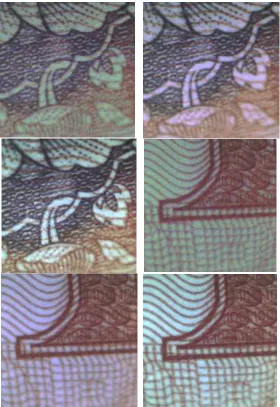
shows two images acquired by bilinear interpolation, edge oriented interpolation, and improved interpolation. TABLE I lists the PSNR of the two images acquired. As can be seen from Fig.2 and TABLE I, the proposed interpolation algorithm performs better than bilinear and edge oriented interpolation algorithm, and its complexity doesn’t increase.
[image:5.612.158.438.135.542.2]
Figure 2. Images acquired using different interpolation algorithms (From left to right: bilinear interpolation, edge oriented interpolation, improved interpolation).
TABLE I. PSNR OF THE IMAGES. Tested
images
Color channels
PSNR of bilinear algorithm
PSNR of edge oriented algorithm
PSNR of improved algorithm
1
R 29.8124 33.702 36.329
G 29.440 32.432 37.783
B 30.123 34.955 36.712
2
R 29.137 33.716 39.383
G 29.241 32.608 38.476
REFERENCES
1. Color imaging array. Bayer B E. U.S. Patent 3971065. 1976.
2. Kiku D, Monno Y, Tanaka M, et al. “Beyond color difference: residual interpolation for color image demosaicking.” IEEE Transactions on Image Processing, 2016, 25(3): 1288-1300.
3. Duran J, Buades A. “Self-similarity and spectral correlation adaptive algorithm for color demosaicking.” IEEE transactions on image processing, 2014, 23(9): 4031-4040.
4. Rani, K. Sudha, and W. Jino Hans. "FPGA implementation of bilinear interpolation algorithm for CFA demosaicing." Communications and Signal Processing (ICCSP), 2013 International Conference on. IEEE, 2013.
5. Wang, Chengyou, Baochen Jiang, and Hao Yuan. "Comparison of interpolation methods in Bayer CFA image compression based on structure separation and APBT-JPEG." J. International Journal of Signal Processing Image Processing & Pattern Recognition 7.1 (2014): 87-98.
6. Ramanath, Rajeev, et al. "Demosaicking methods for Bayer color arrays." Journal of Electronic imaging 11.3 (2002): 306-315.
7. Hibbard R H. Apparatus and method for adaptively interpolation a full color image utilizing luminance gradients: US, 5382976[P].
8. Chen, Xiangdong, et al. "Multidirectional weighted interpolation and refinement method for Bayer pattern CFA demosaicking." IEEE Transactions on Circuits and Systems for Video Technology 25.8 (2015): 1271-1282.