2016 International Conference on Manufacturing Science and Information Engineering (ICMSIE 2016) ISBN: 978-1-60595-325-0
Minimum-Variance Ultrasonic Beamforming
Implemented on High-Performance Desktop
and Embedded GPUs
JUNYING CHEN, JINHUI CHEN and HUAQING MIN
ABSTRACT
Ultrasonic imaging is a widely-used medical diagnostic imaging technique, which is commonly used to observe heart movements, blood flow and fetal developments. The widespread imaging algorithm for ultrasonic imaging is delay-and-sum beamforming algorithm. This algorithm is easy to implement and fast to achieve real-time performance. However, its image quality is not high enough for some complicated diagnostic scenarios. In these cases, advanced algorithms with higher image quality is required. As such, we studied minimum-variance ultrasonic beamforming algorithm which can improve ultrasonic imaging quality, and implemented it on both high-performance desktop and embedded GPUs. By applying our GPU implementation scheme, the desktop or embedded GPU implementation performance was more than 80x better than its CPU or ARM processor counterpart. 1
INTRODUCTION
Medical ultrasonic imaging technologies have been widely used and rapidly developed recently [1, 2]. Ultrasonic imaging technique has advantages such as real-time performance, high safety and low cost. Therefore, it is usually used to observe heart movements, blood flow and fetal developments. Current wide-spread common ultrasonic imaging algorithm is delay-and-sum (DAS) beamforming, which is easy to implement on various computing platforms and fast to achieve real-time performance. However, although the output image quality of DAS beamforming is sufficient for many diagnostic cases, its image quality cannot provide enough anatomical details for some complicated diagnostic scenarios. As a result, we
1
studied minimum-variance (MV) beamforming technique which improved the output image quality, so that it can provide more anatomical details which increased the diagnostic correctness.
MV beamforming technique outputs high-quality images at the expense of computational complexity, i.e., its computation is time-consuming. Such computational complexity hinders MV beamforming technique to implement in real-time on conventional computing platforms such as conventional CPU and ARM processors. As such, we explored MV implementations on high-performance desktop and embedded graphics processing units (GPUs) to evaluate the real-time capability of MV beamforming algorithm. The following sections will describe MV algorithm, GPU implementation scheme, evaluation experiments and result discussions.
MINIMUM-VARIANCE BEAMFORMING ALGORITHM
According to medical ultrasound minimum-variance beamforming algorithm development[3-5], we implemented the MV algorithm with the following descriptions.
MV beamforming algorithm is developed based on the DAS beamforming algorithm framework. They have the same input and output data flow, and the same delay-and-sum process. The major difference is that MV beamforming algorithm uses apodization weights adaptive to input ultrasound data, while DAS beamforming algorithm uses fixed apodization weights which are not adaptive to the input data. This major difference is the reason why MV beamforming algorithm has higher output image quality as compared to DAS beamforming.
In MV beamforming, sub-aperture averaging is applied. A receive aperture is constructed by M continuous input data channels, and segmented into a set of sub-apertures with L consecutive input channels. Therefore, (M − L + 1)sub-apertures are constructed. With sub-aperture averaging, the covariance matrix for image pixel
p0 can then be calculated as:
𝐑(p0) =M−L+11 ∑M−L+1k=1 𝐱k(p0)𝐱Hk(p0) (1)
where 𝐱k(p0) is a (L × 1) vector of input data in kthsub-aperture, i.e., 𝐱k(p0) is the assemble of kthto (k − L + 1)th elements in 𝐱(p0), while 𝐱(p0) is a (M × 1) input
data vector. After 𝐑(p0) is calculated, adaptive apodization weights are estimated as:
𝐰(p0) =𝐚H𝐑𝐑−1−1(p0)𝐚(p
where 𝐚 is the steering vector with simply all ones. This is because the input channel data is already delayed. Finally, the amplitude estimate of the image pixel p0 is obtained by:
z(p0) =M−L+11 ∑ 𝐰H(p
0)𝐱k(p0)
M−L+1
k=1 (3)
GPU IMPLEMENTATION SCHEME
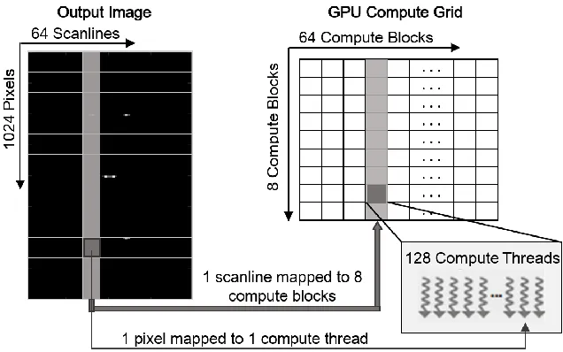
We use Figure 1 to illustrate our GPU programming architecture [6] and its implementation scheme of MV beamforming algorithm. There are three programming hierarchy levels in GPU programming architecture, they are: grid, block and thread. When a GPU computing kernel is invoked, all of its computing statements are within one GPU compute grid. A GPU compute grid calculates a whole medical ultrasound image by decomposing an output target image into scanlines and pixels. Therefore, there is a matrix of compute blocks inside a GPU grid. Each block handles one scanline’s pixel amplitude estimates, while each thread computes one pixel amplitude estimate, as interpreted in Equation (3). To obtain the final value of a pixel amplitude estimate, the algorithm details described in the previous section are implemented in a bunch of parallel computing threads. They can cooperate via shared memory to calculate independent pixel estimates simultaneously. The best practices of the block size and thread size relied on the computing platform resources and the computational problem size.
Figure 1. GPU programming architecture and implementation scheme.
EVALUATION EXPERIMENTS AND RESULT DISCUSSIONS
The experiments used Field II simulator [7] to simulate the ultrasound channel data samples. The simulation simulated a 128-element ultrasonic transducer with 0.3048mm element pitch, using a 5KHz pulse repetition rate and 40MHz sampling rate. The simulated experimental scenario is shown in Figure 2(a). The experimental high-performance desktop and embedded GPU computing platform was NvidiaGTX 980 Ti and NvidiaJetson TK1 evaluation platform respectively. The implementations followed our implementation scheme described in previous section. Figure 2(b) illustrates the MV beamforming output image of the experimental scenario, which demonstrates MV beamforming’s high image quality.
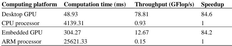
[image:5.612.110.481.414.488.2]The computation time of MV beamforming algorithm on high-performance desktop and embedded GPUs for a specific experiment case are shown in Table I. The computation time of their CPU and ARM processor counterparts are also shown in Table I. As seen from Table I, both desktop and embedded GPU implementations achieved more than 80x speedup as compared to related CPU and ARM processors. As a result, MV beamforming algorithm implementation on clinical medical ultrasound machines can be made possible by using such GPU implementation scheme.
TABLE I. IMAGING PERFORMANCE FOR VARIOUS COMPUTING PLATFORMS (NUMBER OF OPERATIONS = 3856400384OPS).
Computing platform Computation time (ms) Throughput (GFlop/s) Speedup
Desktop GPU 48.93 78.81 84.6
CPU processor 4139.31 0.93 1
Embedded GPU 304.27 12.67 84.2
ARM processor 25621.33 0.15 1
CONCLUSIONS
ACKNOWLEDGEMENTS
This work is supported by “Guangzhou Science and Technology Program” (Key Laboratory Project, No. 15180007) and “the Fundamental Research Funds for the Central Universities (No. 2015ZM081)”.
REFERENCES
1. Havlice, J.F., and Taenzer, J.C. 2005. “Medical ultrasonic imaging: An overview of principles and instrumentation,” IEEE Trans. Ultrason. Ferroelectr. Freq. Control, 67(4), pp. 620-641. 2. Szabo, T. L. 2013. “Diagnostic Ultrasound Imaging: Inside Out,” Academic Press, pp. 832. 3. Synnevag, J.-F., Austeng, A., and Holm, S. 2007. “Adaptive Beamforming Applied to Medical
Ultrasound Imaging,” IEEE Trans. Ultrason. Ferroelectr. Freq. Control, 54(8), pp. 1606- 1613. 4. Synnevag, J.-F., Austeng, A., and Holm, S. 2009. “Benefits of Minimum-Variance Beamforming
in Medical Ultrasound Imaging,” IEEE Trans. Ultrason. Ferroelectr. Freq. Control,56(9), pp. 1868-1879.
5. Chen, J., Yu, A. C. H. and So, H. K.-H. 2012. “Design Considerations of Real-time Adaptive Beamformer for Medical Ultrasound Research using FPGA and GPU,” Int. Conference on Field-Programmable Technology (ICFPT), Dec 10-12. 2012.
6. Cheng, J., Grossman, M., and McKercher, T. 2014. “Professional CUDA C Programming,” Wrox Press, pp.528.