2016 International Conference on Electronic Information Technology and Intellectualization (ICEITI 2016) ISBN: 978-1-60595-364-9
PID Neural Network Motor
Synchronization Control Based on the
Improved PSO Algorithm
Zhenxin Gao and Jianhong Sun
ABSTRACT
PID neural network controller was designed, and the adaptive mutation particle swarm optimization (PSO) algorithm was adopted to optimize its initial weights. The adaptive mutation PSO-PIDNN learning algorithm of motor synchronization control was put forward. According to the need of engineering, the algorithm was simplified. In proportion of multiple motor synchronization control system simulation showed that the simplified PSO-PIDNN controller also can effectively realize the motor synchronization control, solve the problem about the parameter setting is not easy for traditional PID control, and has good stability, fast convergence speed, and no overshoot.
INTRODUCTION
Multi-motor synchronization control is the core problem in printing, paper, binding, textile and other mechanical transmission system with high precision, high speed. The stand or fall of synchronous control algorithm directly affects the system's reliability and the quality of the products[1].
Because of its simple structure, good robustness, high reliability and other features, traditional PID[2] synchronous control is widely used in the synchronous control system. But the key problem of designing PID controller is how to choose
____________________________
the proportion, integral, differential coefficient, and it makes the application of PID controller is restricted. In order to overcome the shortcoming of traditional PID controller, control community puts forward some methods of PID setting. For example, the literature[3]set PID fuzzy control algorithm, but the realization of the fuzzy control is too dependent on human experiences and the scope of its application was very limited. In order to achieve effective control, the neural network was introduced into synchronous control system. Literature [4] uses the combination of neural network and fuzzy algorithm, but its underlying layer is overmuch, increase the complexity of the system and the amount of calculation. Literature [5] uses single neuron PID synchronous control, this kind of single-layer network only has linear classification ability, can't make simple logic operations, so this controller in the complex system is difficult to achieve good performance.
Due to the learning convergence speed of general neural network is slow, easily trapped in local minimum point and there is no guarantee for real-time control system. At the same time, the hidden layer unit number and the connection weights is difficult to determine, thus restricting its extensive applications in control system. Literature [6] proposes a new type of neural network model―PID neural network (PIDNN) model. The PIDNN is an amalgam of PID control and neural network, thus it has the advantages of neural network and PID control and overcome the shortcomings of traditional control method and the general neural network.
Particle swarm optimization (PSO)[7] is a kind of new, global optimization algorithm. It obtained the ideal effect in terms of solution to find the optimal solution. Compared with genetic algorithm, PSO has no crossover and mutation operation, and just through internal speed to update particles. Its principle is simpler, less parameters and easier.
In conclusion, this paper designs the PSO - PIDNN controller and simulated for the parallel multiaxial proportional synchronous control system. PSO-PIDNN uses PSO algorithm to define the PIDNN hidden layer to output layer weights, and makes it has better convergence direction from the start. Moreover, according to the engineering requirements, we make some optimization.
PROPORTION OF MULTI-MOTOR SYNCHRONIZATION CONTROL STRATEGY
In no axis synchronous motor control system, the running between the drive shafts need to maintain a certain speed. Synchronized proportional relationship
commonly is w1y1 w2y2 ... wnyn. When the motor synchronous ratio wi
is 1, it’s the most simple synchronous relationship. But in actual production, running between the motor need according to the different proportion, as:
n n
w w
Current motor synchronization control strategy have parallel, master-slave control, virtual control total shaft coupling control, cross coupling control and deviation control and so on[8-11].
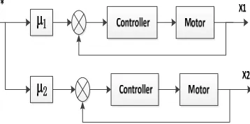
[image:3.612.215.394.174.263.2]In parallel synchronous control, each shaft has a good synchronization performance. The system uses this control structure without instruction time lag, can extend the number of shaft and has a simple structure. In multi-axis synchronous
Figure 1. Proportion of multi-motor synchronization control model.
control system, it is widely used. In this paper, the model uses parallel type synchronous control with 2 motors as actuators. The synchronous control method is shown in figure 1.
PERMANENT MAGNET SYNCHRONOUS MOTOR
In the motor shaft less synchronous control system, permanent magnet synchronous motor, with simple structure, reliable operation, high power factor, large torque at low speed, is widely used. But it is a nonlinear, strong coupling, multi-variable system, and need through some changes to convert to dc motor features and modeling[12]. In engineering design, in order to simplify the analysis of the problem, we have to simplify and get simplified model for permanent magnet synchronous motor[13]:
) (
) (
)
( 2
m e m m
m
K K Rf s L f JR JLs
K s
G
(1)
L、R、I are the armature winding inductance, resistance and current; Ke is
counter electromotive force proportion coefficient; Km is the moment coefficient of the motor; J is the moment of inertia of the motor shaft; fm is the damping coefficient.
Using the two same motor servo system, and the parameters for:
J=0.1982013kg·m3;fm=10-4N·m/(rad·s-1);R=25Ω;L=0.3744 H; Km=0.727
2034 . 0 * 81578 . 6 * 10207231 . 0 1 ) ( 2 s s s G (2)
We have the discretization process for formula(2) and use zero order retainer with sampling period ts = 0.01 s, having
) 2 ( 0003179 . 0 ) 1 ( 0003968 . 0 ) 2 ( 5129 . 0 ) 1 ( 513 . 1 )
(k y k y k u k u k
y (3)
SYNCHRONOUS CONTROL ALGORITHM WITH MULTI-MOTOR
PID Neural Network (PIDNN)
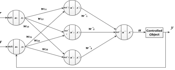
Traditional PIDNN is a three layer forward neural network with 2*3*1 structure. The features of PIDNN is that the middle layer defines the proportion, integral and differential three neurons ,equivalent to put PID control into the neural network and make it has a good network dynamic characteristics. Figure 2 is the PIDNN structure.
THE PIDNN CONTROLLER ALGORITHM AND VALUE FUNCTION
Figure 2 illustrates the forward algorithm consists of input layer and hidden layer and output layer. PIDNN hidden layer has three neurons, they are proportion, integral, and differential dollar. The status of each neuron and input/output function in the forward algorithm as shown in literature [6].
Value function is the basis of neural network training, commonly used with the mean square error function. Whole neural network uses the minimum mean square error (MSE) as the training of learning principles and objectives. The weights of each layer of PIDNN controller forward propagation and error back propagation is constant adjustment, and this is neural network training process.
PIDNN according to the gradient descent method is used to correct the weights of the network. In order to improve the convergence speed of learning process, to add a momentum factor with weight learning. The following type:
) 1 ( ) ( ) (
w k
w k E k w li li
li
Figure 2. PIDNN control system structure.
In type,
is the learning rate, is the inertia coefficient, k is the sampling time,) (k wli
is a weight correction, E(k) is the mean square error (MSE) value.
CONNECTION WEIGHTS INITIAL VALUE SELECTION OF PIDNN
(1)The initial value selection for input layer to hidden layer connection weights According to the characteristics of the PID control algorithm: e(k)=r(k)-y(k), selecting the input layer to hidden layer connection weights of the initial value and make the tracking error e as an intermediary input neurons. So input layer to hidden layer connection weights of the initial value are
1, 1 (5)
(2)The initial value selection for hidden layer to output layer connection weights Select PIDNN hidden layer to output layer connection weights of the initial value and make the PID connection weights output when the initial value is equivalent to PID controller output. Selecting
′ ; ′ ; ′ (6)
Particle swarm optimization (PSO) algorithm is used to select the PIDNN kp, ki, kd initial value, so as to learning process is easy to fall into local optimal value and learning rate is slow when solving the initial weights randomly.
Particle Swarm Optimization (PSO)
According to the literature[7], the particles update their speed Vi and location Xi by following type. Namely, the standard PSO algorithm:
)) ( (
)) ( (
) ( ) 1
(k wV k c1 rand1 pbest X k c2 rand2 gbest X k
Vi i i i i (7)
) ( ) ( ) 1
(k X k V k
Xi i i (8)
In type: i=1,2,3...M, is populations in the algorithm; pbesti is the optimal position of each particle; g best is the best location for population; k is the number of iterations; w is inertia weight;c1 and c2 are two positive acceleration coefficient, generally taking c1 = c2 = 2;rand1 and rand2 as a random number between [0, 1].
PARAMETER ANALYSIS [15]
A. Linear adjustment strategy B. random inertia weight strategy
Figure 3. Simulation of different inertia weight adjustment strategies.
The selection of appropriate inertia weight w can better balance the global search
and local search ability of the algorithm. Inertia weight coefficient adjustment strategy which are frequently used has linear adjustment strategy and random inertia weight strategy.
Figure 3 is respectively using two kinds of inertia weight strategy simulation diagram. We can see from the figure 3, random inertia weight strategy achieving stability needs far less iterations than linear adjustment strategy. In the analysis of dynamic nonlinear problem of synchronous control, random inertia weight strategy was adopted to choose w, namely: w=0.5+rand()/2
0 10 20 30 40
0.0663 0.0664 0.0664
PSO evolution process (linear adjustment strategy )
the number of iterations
fitn
e
ss
0 10 20 30 40
0.0664 0.0664 0.0664 0.0664 0.0665
the number of iterations
fit
n
e
ss
ADAPTIVE MUTAION PSO ALGORITHM
Due to PSO has some disadvantages, such as premature convergence, low search accuracy and late iterative efficiency. This paper improves the standard particle swarm optimization algorithm, and blends the mutation of genetic algorithm into the particle swarm, that is to initialize some variables again at a certain probability. This can make the particles out of the previous optimal value position and carry out the search in a bigger space, thus improving the ability of algorithm to find the best value.
Introducing the mutation probability Pj. In order to avoid the mutation affects the stability of the algorithm, the mutation probability need to be selected reasonably. Pj is too small may affect the stability of the system, if the Pj is too large, will make small particle in the stagnant for too long, weaken the effect of mutation operator
According to the experiment, taking Pj> 0.9 and occurring variation. The MATLAB code is as follows:
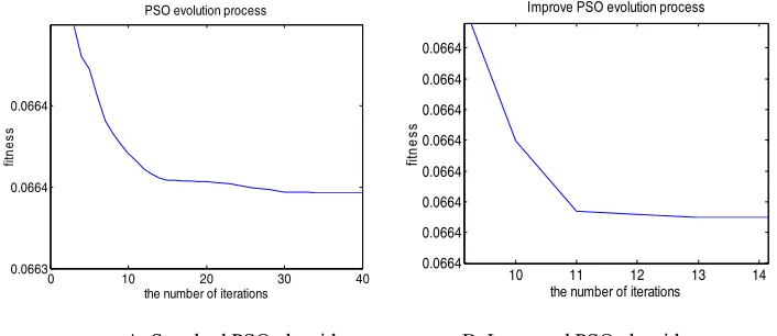
[image:7.612.118.471.319.472.2]A. Standard PSO algorithm B. Improved PSO algorithm
Figure 4. Two optimization simulation diagram of the algorithm.
For k=1:N
Pj=rand()
If Pj>0.9,
Xj(k)=rand
end end
Figure 4 is standard particle swarm optimization algorithm and improved particle swarm algorithm simulation results under the same condition. It can be seen
0 10 20 30 40
0.0663 0.0664 0.0664
PSO evolution process
the number of iterations
fitn
es
s
10 11 12 13 14 0.0664
0.0664 0.0664 0.0664 0.0664 0.0664 0.0664 0.0664
Improve PSO evolution process
the number of iterations
fitn
e
that the adaptive PSO algorithm can quickly jump out of local optimum and come into a stable state, get the optimal solution.
ADAPTIVE MUTATION PSO ALGORITHM PROCESS
The algorithm process is as follows:
(1) The initialization of particle swarm, including population size N, the position of
each particle Xi and velocity Vi.
(2) Calculate the value of each particle function, namely fitness value of the particle. According to the fitness value, the initial position of each particle is set to
individual optimal position pbesti, populations of the optimal location gbestis set
to the global optimal position of the initial particles.
(3) According to the formula (7), (8) to update the particle's velocity Vi and position
Xi; To make adaptive mutation in position of the particles for meeting the
conditions.
(4) Calculate the fitness of each particle value, according to the fitness of each particle, compare the current position and its history optimal location, if it is better than the history optimal location, the current position will be as an individual optimal position, otherwise continuing to use the history optimal location.
(5) For each particle, comparing its individual optimal location and population optimal position, if it is better than that of the optimal location with population, replacement; Otherwise unchanged.
(6) Check whether achieve algorithm termination conditions, if satisfied, terminate the iteration; Otherwise, return (3).
The PIDNN Algorithm Based on Adaptive Mutation PSO
ADAPTIVE MUTATION PSO - PIDNN ALGORITHM OPTIMIZATION
In order to reduce control operation time in engineering, we need to simplify the control algorithm. According to a special relationship with the PIDNN and the PID controller and the analysis of the literature [16], the input layer to hidden layer weights with PIDNN can be fixed that maintain the initial values the same, only for the hidden layer to output layer weights are modified.
PIDNN ALGORITHM PROCESS BASED ON ADAPTIVE MUTATION PSO
(1) The initialization of each particle search scope, speed, initial position, each group of particle number, group number, the learning efficiency, etc. Initialize the PIDNN input layer to hidden layer weights.
(2) Run adaptive PSO algorithm, return population optimal position, namely the
PIDNN hidden layer to output layer weights kp, ki, kd.
(4) According to the value function, carrying on the back propagation arithmetic, updating the PIDNN hidden layer to output layer weights.
(5) Compute system output.
(6) Return(3) and cycle calculation. When reach cycles, terminating calculation and drawing.
SIMULATION AND ANALYSIS
Making input r = 1, scale factor 1 = 1, 2 = 0.8; Using MTALAB simulation
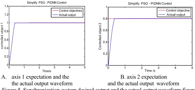
for parallel type proportional synchronization control system. Population size is 20, particle dimension is 3, iteration for 50 times, the input signal sampling points is 500. Particles search range is [-30, 30], maximum speed is [3, 3]. The simulation waveform in motor synchronization control system is shown in figure 5.
[image:9.612.133.472.302.459.2]A. axis 1 expectation and the B. axis 2 expectation the actual output waveform and the actual output waveform
Figure 5. Synchronization system desired output and the actual output waveform figure.
The simulation results can be seen in figure 5, the simplified adaptive mutation PSO - PIDNN algorithm enables the system axis 1 and 2 output without overshoot phenomenon, and can quickly reach the stable state, has good quickness and adaptability, meets the requirements of synchronous control system in industrial
control. Moreover the PID parameters kp, ki, kd selection does not need to rely on the
experience of artificial selection and engineering subjects, and has a certain universality.
CONCLUSIONS
For proportion of synchronous control system based on multiple motor, the synchronous controller is designed, and adaptive mutation PSO-PIDNN synchronous control algorithm was presented. The initial PIDNN weight was
0 1 2 3 4 5
0 0.2 0.4 0.6 0.8 1 1.2
1.4 Simplify PSO - PIDNN Control
co
nt
ro
lled
o
b
je
ct
1
Time/s
Control objectives Actual output
0 1 2 3 4 5
0 0.2 0.4 0.6 0.8 1
Simplify PSO - PIDNN Control
C
ont
rol
led
obj
ect
2
Time /s
determined with adaptive mutation PSO algorithm, and it can solve the shortcomings that learning process is easy to fall into local optimal value and learning rate is slow when the initial weights is random, also avoid the disadvantages for the traditional PSO search precision is low and late iterative efficiency is not high. Then analyzing the selection of the PSO inertia weight, and choosing the weight adjustment strategy which suitable for synchronous control system. Finally, in the process of PIDNN training, network input layer and output layer weights are set for fixed values according to the actual system. It greatly reduces the computational complexity and improves the practicability of synchronous controller. Optimization of adaptive mutation PSO - PIDNN controller has good adaptability and quickness, no overshoot by simulation analysis. In addition, it solves the disadvantages of the traditional PID control parameters selection difficultly, and can effectively realize the motor synchronization control performance, can meet the engineering requirements about synchronized control system.
ACKNOWLEDGEMENTS
This work has been supported by the Production Research funding of joint innovation of Jiangsu Province of China (Grant No. BY2014004-08).
REFERENCES
1. Fu-cailiu, Zhang Xuelian Liu Liwei. Multi-stage synchronous motor drive system control theory and application research on what]. Control Engineering. 2002, 9 (4): 87-90. (In Chinese)
2. You-rui Huang, Li-guo Qu. The PID controller parameter setting and implementation [M]. Beijing: Science Press, 2010. (In Chinese)
3. Pengfei-li, Wei-tao Wang, Yabin-wang. Fuzzy PID based on adjacent deviation coupling motor synchronization control [J]. Mechanical Design and Research, 2013, 29 (5), 45-48. (In Chinese)
4. Zhang Jing. Shaftless drive printing machine synchronous control system research D.Wuhan: Huazhong University of Science and Technology, 2012. (In Chinese)
5. Xingang-miao, Su-Wang, Lingpang-Han, etc. Based on the deviation coupling of single neuron synchronous motor control [J], Micro-motor, 2011, 2, 44-47. (In Chinese)
6. Huailin-shu. Neural network and its control system. [M], Beijing: national defense industry press, 2006. (In Chinese)
7. Kennedy J., Eberhart R.C. Particle swarm Optimization [C]. Proceedings of IEEE International Conference on Neural Networks. New York: IEEE Press, 1995: 1942 - 1948.
8. Shim H.M., Hong J.P., Chung S.B. Powered wheelchair controller based on master-slave control architecture industrial electronics [J]. IEEE International Symposium, 2001(3): 1553~1556.
10. Valenzuela M.A., Lorenz R.D., Electronic line-shafting control for paper machine drives[J].Industry Applications, IEEE Transactions on. 2001, 37(1): 158-164.
11. Perez-Pinal F., Caladeron G., AraujoI. Relative Coupling Strategy. IEEE, IEMDC 03, Madison Wisconsin USA. 2003, 2(6): 1162-1166.
12. Noriel. Permanent magnet synchronous motor drive system control strategy study [D] Master Thesis of Zhejiang University, 2014. (In Chinese)
13. JianHong-Ji, Jinda-Ca. Arm9-based and adaptive fuzzy PID algorithm of honeycomb cardboard flying shear control system [J]. Packaging Engineering, 2013, 21, 75-79. (In Chinese)
14. Al-Othman A.K., Abdelhamid T.H. Elimination of harmonics in multilevel inverters with non-equal DC sources using PSO [C]//IEEE Power Electronics and Motion Control Conference. Poznan, IEEE, 2008: 606-613
15. Feng-qian. Particle swarm optimization (PSO) algorithm and its industrial application [M]. Beijing: Science Press, 2013.(In Chinese)