PID Neural Network Motor Synchronization Control Based on the Improved PSO Algorithm
Full text
Figure


Related documents
Therefore, in the Internet of things, the BP network topology used in the classification experiment of the data set is: 10 input layer nodes, 24 hidden layer nodes, and 6 output
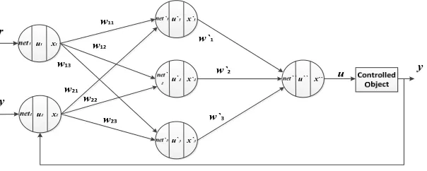
variable selection considering external influence factors, the input structure of the neural network structure. is 5 nodes, the hidden layer is 1 node, and the output layer is
By applying the improved genetic algorithm, for different types of attacks, the optimal number of hidden layers and neurons in a hidden layer can be
The RBF network is consist of two layers except input layer, the hidden layer and output layer, where the network with feed forward and contain two types of training,
The BLDC motor with variable input source was controlled using PSO-PID controller and the SEPIC converter. The SEPIC converter regulates the input voltage of the
is determined by the function of the input layers and the weights on the connections between the input and the hidden layer. The behavior of the output
Neural network structure is 5×100×1(input layer: 5 nodes, hidden layer: 100 nodes, output: 1 node).In the training process, 5 critical part measurements (chest 、 waist 、 shoulder
SUM is collection of the output nodes from hidden layer that have been multiplied by connection weights, added to get single number and put through sigmoid function