SETC2009
2009-32-0018/20097018
Analysis of Relation between Mixture Formation during
Ignition Delay Period and Burning Process in Diesel
Combustion
Amir Khalid, Tomoaki Yatsufusa, Takayuki Miyamoto, Jun Kawakami, Yoshiyuki Kidoguchi
The University of Tokushima
Copyright © 2009 SAE Japan and Copyright © 2009 SAE International
ABSTRACT
Many technologies for reducing exhaust emissions of wide variety of diesel engines from small size to large size ones have been considered with the improvement throughout the combustion process. To reduce emissions, mixing of fuel and air is still important phenomena.
Purpose of this study is to clarify the relation between mixture formation during the ignition delay period and burning process in diesel combustion that strongly affects the exhaust emissions. In this study, a rapid compression machine was used to simulate actual phenomenon inside the combustion chamber with changing ambient density. In addition, swirl velocity and injection pressure were changed as experimental parameters to improve mixture formation at high ambient density. This study constructed schlieren photography system with a high-speed digital video camera to investigate the detail behavior of mixture formation during ignition delay period. This method can capture spray evaporation, spray interference and mixture formation process clearly. Ignition process and flame development were investigated by direct photography method using a light sensitive high-speed color digital video camera. The sensitive camera can capture flame development clearly with the mixture of dark and bright flames. Moreover, the mechanism and behavior of flame pattern were analyzed by newly developed image analysis technique.
Flame images reveals that spray ignition occurs with dark flame between sprays at the middle and downstream of the spray where combustible mixture is first formed; then bright flame appears near the centerline of each spray where fuel is continuously injected to rich and high temperature atmosphere. Increasing ambient density restrains spray tip penetration, resulting that mixture is only formed at the center region of the combustion chamber. It is necessary for high ambient density condition to improve mixture formation. High-pressure injection is most effective in
improvement of mixture formation under condition of high ambient density.
INTRODUCTION
The diesel engines are still widely needed and applicable to wide variety of applications from small to large sizes. Despite years of improvement attempts, diesel engines still have problem of emitting NOx and Particulate Matter (PM) into the atmosphere. Thus, the improvement of emissions exhausted from diesel engines is urgently required to meet the future stringent emission regulations.
Diesel combustion is by nature heterogeneous combustion. NOx is formed at high temperature and stoichiometric mixture region; on the other hand, PM is emitted at rich region. It is known to control mixture formation is indispensableto improve exhaust emissions from diesel engines[1-7]. In particular, mixture formation during ignition delay period is important process because ignition is controlled by physical process caused by multi-hole injection and air motion and chemical process of fuel decomposition and oxidation[8]. Ishiyama et al.[9] has reported that, in diesel combustion, fuel gasification, thermal cracking and oxidation process begin at early time during ignition delay period. The authors reported the concepts of the evaporation of spray droplets, atomization of a spray. In the report, it was suggested that mixture is first formed at spray boundary at middle stream of the spray[10]. It is complicated to understand ignition because above two processes progress simultaneously during ignition delay period; moreover, there are a lot of design parameters related to mixture formation.
injection pressure has a great effect on the mixture formation, ignition delay, flame pattern, turbulence, ambient density and ambient pressure, then affects to the flame development, combustion characteristics and emissions elements. Although some results have been reported to improve emissions by the concept of improving mixing[6], it is necessary to make clear the effect of every design parameter on mixture formation and combustion in detail.
Authors have started research to investigate mixture formation focusing on ignition delay period[12][13]. In our previous reports, we investigated the relation between mixture formation and design parameters such as swirl velocity, injection pressure and number of holes (hole diameter) using schlieren photography method. It is suggested that there is optimum relation between spray momentum and air motion caused by design parameters. Next, it is necessary to make clear the relation between combustion characteristics and physical phenomena such as air entrainment and mixing ratio. To go forward to the next step, effect of other parameters such as ambient density and ambient temperature on mixture formation should be also investigated, as high boost combustion, that is high ambient density, is important technology for the future diesel engines.
This study investigates the effectsof ambient density on mixture formation and combustion process using schlieren photography and direct photography methods with a rapid compression machine; then tries to make clear the mixture formation during ignition delay period and flame development. In addition, this study intends to improve mixture formation at high-density condition.
EXPERIMENTAL SETUP
Rapid Compression Machine and Injection System
A free-piston type rapid compression machine (RCM) was used to simulate diesel combustion in a constant volume over a wide range of ambient temperature and pressure conditions similar to actual diesel engines as shown in Fig.1. Details of this device have been described in the previous report[14]. The spray chamber was disc type with a diameter of 60mm and a width of 20mm. One of the base surfaces of the chamber was composed of pyrex glass to observe spray and flame developments, and the other side surface had a injector holder. Piston motion induced air inside the chamber. A swirler with a 14mmX16mm-size connecting port installed at inlet of the chamber created swirl flow inside the chamber. The port inclination angle controlled swirl velocity. Swirl velocity was defined as the velocity at 2/3-location of radial direction from the chamber center. Base swirl velocity rs was rs=19m/s in this study. This
swirl velocity corresponds to the standard swirl velocity of the real engine in our laboratory.
Baseline ambient conditions at start of injection were ambient temperature of Ti=850K and ambient pressure
of pi=4MPa. Ambient density was ρ=16.6kg/m3 at
baseline condition. This study changed ambient pressure by changing initial charging pressure pc before
compression by the piston. The increasing ambient pressure simulated high boost pressure condition. The ambient pressure pi were changed to pi=4MPa
(pc=100kPa), 6MPa (pc=150kPa), and 8MPa
(pc=200kPa) with keeping ambient temperature of
Ti=850K. At every condition, ambient density ρ was ρ=16.6kg/m3 (pc=100kPa), ρ=25.0kg/m3 (pc=150kPa), ρ=33.3kg/m3 (pc=200kPa), respectively. A common rail
fuel injection system and a six-hole injector with hole-diameter of dn=0.129mm were used to inject JIS#2
diesel fuel (a density of 836kg/m3 and lower heating value of 42.7MJ/kg) into the spray chamber. The injector was set at the center of the chamber base surface. The injection pressure Pinj was varied at 100MPa (baseline)
and 160MPa by using this common rail system. Varying injection duration controlled the amount of injected fuel. This study kept injection quantity at q=0.05 ml. The injection durations were 2ms for Pinj=100MPa and 1.5ms
for Pinj=160MPa. Therefore, equivalence ratio φ was
changed according to the ambient density; that is, φ=0.40 for ρ=16.6kg/m3, φ=0.26 for ρ=25.0kg/m3 and φ=0.20 for ρ=33.3kg/m3, respectively. Injection
commencement was measured from the needle lift detected by a hole sensor installed in the injector.
Gas pressure inside the combustion chamber was measured by a piezoelectric pressure transducer (Kistler, 601A). NOx concentration was measured by a chemiluminescence analyzer (Yanako, ECL-77A). The heat release rate dQ/dt was calculated from the combustion pressure. This study introduced two types of chamber pressure marked with pf and pa. The pf is the
pressure in the combustion chamber when air is compressed and combustion occurs. The pressure change is resulting from competition between endothermic process such as fuel evaporation, decomposition and heat loss to the chamber wall, and exothermic process i.e. combustion. In contrast,
SETC2009
pressure pa is the pressure when air is compressed
without fuel injection. In this case, the pressure pa
gradually decreases as time passes by the heat release to the chamber wall after the end of compression. Of course, pf also experiences the heat loss to the wall.
Therefore, pf - pa roughly represents the net pressure
history excluding the effect of the heat loss to chamber wall. At early ignition delay period, the pf -pa shows
negative because of fuel evaporation and thermal decomposition without oxygen. In this case, pressure drop is mainly controlled by fuel evaporation. When chemical reaction involving heat release becomes predominant, it will increase as pressure recovery. In this case, pressure drop is mainly controlled by heat loss. Ignition delay was defined as time from start of injection to the early time when the pf -pa reaches zero.
EXPERIMENTAL RESULTS
The Effects of Injection Pressure and Swirl Velocity on Mixture Formation and Initial Flame Development
This section tries to improve mixture formation under the condition of high ambient pressure. As shown in Fig.6, high ambient pressure causes high-density atmosphere, resulting that spray tip penetration is restricted and mixture formation is prevented. This study took two measures to develop spray tip penetration; one was high-pressure injection and the other was low-swirl air motion. Injection pressure was raised from Pinj=100MPa
to 160MPa with keeping the injector specification. When injection pressure is raised in this case, injection rate was increased and injection duration was shortened from 2ms (Pinj=100MPa) to 1.5ms (Pinj=160MPa). Swirl
velocity was decreased from rs=19m/s to 10m/s.
Figure 10 shows histories of combustion pressure and heat release rate. As compared with baseline condition of Pinj=100MPa and rs=19m/s, high-pressure injection
gives early rise of heat release rate. Greater injection rate and promoted both mixing and atomization increase
heat release rate and shorten combustion duration. Low swirl motion lengthens ignition delay; however, heat release rate is high after ignition, leading to short combustion duration. Both high-pressure injection and low swirl have an effect of improving combustion against baseline condition.
[image:3.612.346.537.222.376.2]Next, the improvement of combustion is investigated on the point of mixture formation.
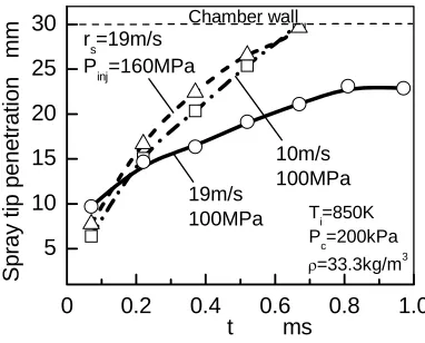
Figure 11 shows spray tip penetration at pc=200kPa with
nitrogen atmosphere and ambient temperature of Ti=850K. It is clearly shown that both high-pressure
injection and low swirl have an effect of promoting spray tip penetration. The sprays impinge on the chamber wall at about t=0.7ms.
Figure 12 compares mixture formation and initial flame development. The schlieren images shown at the first and second rows from the upper reveal that both high-pressure injection and low swirl can make spray tip penetration longer. The long penetration promotes mixture formation near the wall region. High-pressure injection distributes larger amount of fuel between sprays. High injection pressure creates good spray atomization. At low swirl condition, swirl flow can hardly bend the spray although spray penetration is long enough; thus less mixture is formed as compared with high-pressure injection case.
These mixture formation processes affect initial flame development shown in the images at the third and forth rows from the upper. In contrast with the baseline condition of rs=19m/s and Pinj=100MPa, high injection
pressure condition of Pinj=160MPa shows dark flame at
wider region between the sprays around spray tip region as well as middle stream of spray boundary, which is the effect of promoted mixture formation. Meanwhile, at low swirl condition of rs=10m/s, ignition is delayed and dark
flame is observed at small region of the chamber. In addition, smaller amount of flame is observed near the wall. There is little effect of wall impingement due to high ambient density. Images in Fig.12 infer that it is hard for low swirl condition to promote initial mixture formation at high ambient density.
Fig.11 Comparison of spray tip penetration
0 0.2 0.4 0.6 0.8 1.0
5 10 15 20 25 30 10m/s 100MPa 19m/s 100MPa
t ms
rs=19m/s Pinj=160MPa
T
i=850K
P
c=200kPa
ρ=33.3kg/m3
[image:3.612.52.264.468.665.2]Chamber wall S p ra y t ip pe ne tr a ti o n mm
Fig.10 Effect of injection pressure and swirl velocity on combustion process
under high density condition
4 6 8 10 12 14 16 pf MP a 0 1 2 3 19m/s 100MPa 10m/s 100MPa
rs=19m/s
Pinj=160MPa
T i=850K pc=200kPa p
i=8MPa
ρ=33.3kg/m3
dQ
/dt MJ
/s
0 1 2 3 4
t ms
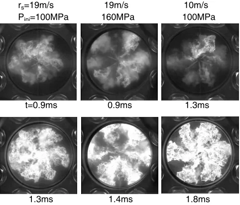
Figure 13 compares flame development after ignition. At baseline condition of rs=19m/s and Pinj=100MPa, as
mentioned in Fig.8, dark flame develops within middle of the chamber and bright flame slowly develops to the wall side region. Increasing injection pressure up to Pinj=160MPa, promoted mixture formation causes dark
flame at wide region of the chamber at initial burning. Comparing bright flame developments between Pinj=160MPa at t=1.4ms and rs=10m/s at t=1.8ms,
wide-size bright flame is observed along spray centerline at low swirl condition of rs=10m/s; furthermore, blank region
without dark and bright flames appears near the wall. It is estimated that low swirl condition cannot fully utilize fresh air in the chamber. On the other hand, at Pinj=160MPa and t=1.4ms, bright flame develops fast
[image:4.612.39.283.49.532.2]and widely at spray tip region. Dark flame is observed between bright flames. Bright and dark flames cover whole the chamber. It is assumed that high-pressure injection accelerates mixture formation all over the chamber and also promotes mixing after ignition.
Figure 14 investigates histories of global flame area in the images. Same as seen in Fig.12 and 13, high-pressure injection of Pinj=160MPa causes dark flame fast
and the flame covers wide area of the chamber; then bright flame develops and it soon goes out due to short combustion duration. At other cases of Pinj=100MPa with
swirl velocities of rs=19m/s and 10m/s, dark flame
covers smaller area than Pinj=160MPa. Flame
development starts later at low swirl case because of long ignition delay.
To investigate time histories of flame distribution and flame intensity quantitatively in detail, this study employed image analysis described in the above section of “Images Analysis Method”.
Figure 15 shows the results of image analysis. The flame images at each condition are analyzed into circular (Fig.15(a)) and radial (Fig.15(b)) distributions. Fig.12 Effect of injection pressure and swirl velocity
on mixture formation and initial flame development Initial flame occurs
0.1ms after initial flame occurs
Swirl
0.6ms
0.7ms 1.1ms
1.0ms 0.6ms
0.7ms
rs=19m/s 19m/s 10m/s
Pinj=100MPa 160MPa 100MPa
t=0.52ms 0.52ms 0.52ms
0.82ms 0.82ms 0.82ms
0.6ms 0.6ms 1.0ms
[image:4.612.329.570.107.313.2]0.7ms 0.7ms 1.1ms
Fig.13 Effect of injection pressure and swirl velocity on flame development
t=0.9ms 0.9ms 1.3ms
rs=19m/s 19m/s 10m/s
Pinj=100MPa 160MPa 100MPa
1.3ms 1.4ms 1.8ms
Fig.14 Effect of injection pressure and swirl velocity on histories of dark and bright flames
0 0.5 1.0 1.5 2.0 2.5 3.0 0
20 40 60 80 100
Bright flame Dark flame
10m/s 100MPa 19m/s
100MPa r
s=19m/s,
Pinj=160MPa
Ti=850K pc=200kPa
ρ=33.3kg/m3
Fl
ame area
rat
io %
[image:4.612.337.545.480.618.2]SETC2009
The horizontal axis indicates time from start of injection and the vertical axis in Fig.15(a) indicates circular angle θ to swirl direction calculated from the centerline of base spray out of six sprays. The centerline of each spray is indicated by broken line in the diagrams. In Fig.15(b), the vertical axis means radial direction from the nozzle center that is also the center of the chamber. The high and low intensity color in the diagrams indicates flame intensity.
As compared with circular distribution of the flames in Fig.15(a), both high-pressure injection and low swirl conditions show dark flames. In particular, high-pressure injection forms dark flame widely between each spray and its intensity is high. This is because fuel is injected with high injection rate and the spray tends to be bended by swirl motion greater than low swirl case. Ignition seems to occur at every region between sprays almost
the same time. Moreover, dark flame is observed relatively long time after the appearance of bright flame at high injection case. It is inferred that mixture is formed whole the chamber at high injection pressure. Low swirl condition shows dark flame at later time due to long ignition delay. Base condition of Pinj=100MPa and
rs=19m/s cannot show dark flame at all regions between
sprays. First ignition occurs at the specific region where combustible mixture is just formed. At the time of ignition, the amount combustible mixture is smaller at baseline condition than high-pressure injection condition.
Bright flame is first observed near spray centerline and a little later than appearance of dark flame at every condition. As bright flame is carried away by swirl flow, it is observed between sprays as time passes. High-pressure injection case shows bright flame relatively short time due to short combustion duration.
Almost same discussion can be made on radial distribution of the flame in Fig.15(b). Similar to circular distribution, high-injection condition shows dark flame at wide region. Dark flame develops mainly at 20-30mm from the center and high intensity dark flame is seen at 20-25mm. The dark flame develops at 20-30mm as time passes. It is assumed that, at high-pressure injection condition, mixture is formed more at spray tip region during ignition delay period. At low swirl condition, dark flame is observed at 20-25mm, which is a bit to the
center. Mixing near the wall region during ignition delay period is insufficient for low swirl case.
As seen from the radial distribution of bright flame, both baseline and low swirl conditions have high intensity region near the center of the chamber and the region hardly moves as time passes. Considering that bright flame comes from rich combustion of intermittently injected fuel, mixing after ignition is insufficient for baseline and low swirl cases. In addition, high intensity bright flame is observed for a long time at baseline condition. This is mainly because mixture is formed
0 0.5 1.0 1.5 2.0 2.5 3.0
0 60 120 180 240 300
θ
degr
ee
t ms 0.5 1.0 1.5 2.0 2.5 3.0t ms
0 60 120 180 240 300
θ
degr
ee
0 60 120 180 240 300 360
θ
d
egre
e
Dark flame Bright flame
Spray centerline
19m/s 100MPa
19m/s 160MPa
10m/s 100MPa
0 0.5 1.0 1.5 2.0 2.5 3.0
0 5 10 15 20 25
r mm
t ms 0.5 1.0 1.5 2.0 2.5 3.0t ms
0 5 10 15 20 25
r
mm
0 5 10 15 20 25 30
r mm
Injector outlet
19m/s 100MPa
19m/s 160MPa
10m/s 100MPa
Dark flame Bright flame
55
0 100 0
(a) θ direction (b) r direction
mainly at center of the chamber during ignition delay period and fuel is being injected into rich region at baseline condition. Contrarily, bright flame has lower intensity at high-injection condition. Bright flame disappears sooner than base and low swirl conditions; main reason is that, at high-injection pressure case, mixing is promoted after ignition, and the other region is that it is short injection period.
CONCLUSIONS
This study investigated the effects of mixture formation on ignition and combustion of a multi-hole diesel spray. Experiment was carried out using rapid compression machine. Flame development was analyzed in detail using optical flame-visualizing system with digital video cameras. Effects of ambient density on mixture formation were first investigated by changing ambient pressure with keeping ambient temperature. To improve mixture formation during injection period at high-density condition, high-pressure injection and low swirl motion were employed. The results are summarized as follows.
1. Spray ignition occurs with dark flame between sprays at middle and downstream of the spray where combustible mixture is first formed; then bright flame appears near the centerline of each spray where fuel is intermittently injected to rich and high temperature atmosphere. Dark flame is one of signal that tells the region where well-mixed mixture is prepared.
2. Increasing ambient density shortens ignition delay. High heat capacity at spray boundary resulting from high density mitigates temperature drop of ambient gas, and promotes formation of combustible mixture. However, this condition tends to produce high intensity bright flame due to locally rich combustion and lengthen combustion duration. It is important to improve mixture formation so as to fully consume oxygen under high ambient density condition.
3. Both high-pressure injection and low swirl motion lengthen spray tip penetration and promote mixture formation at spray tip region near the chamber wall; however, mixture is distributed at smaller region under low swirl condition than high-pressure condition.
4. High-pressure injection promotes mixture formation during ignition delay period and large amount of combustible mixture is formed; therefore, after ignition, dark flame develops widely at spray tip region and between sprays before appearance of bright flame. Furthermore, bright flame has less intensity due to well mixing.
REFERENCES
1. Matsui, Y., Kimura, S., Koike, M., “A New Combustion Concept for Small DI Diesel Engines – 1st Report : Introduction of the Basic Technology ”, Trans. of JSAE, 28-1, pp.41-46, 1997.
2. Takeda, Y., Nakagome, K., Niimura, K., “Emission Characteristics of Premixed Lean Diesel Combustion with Extremely Early Staged Fuel Injection”, Trans. of JSME, Series B, 62-599, pp.2887-2894, 1996.
3. Sasaki, S., Ito, T., Iguchi, S., “Smokeless Low-Temperature Diesel Combustion Concept (First Report) – Soot-less Combustion at a Near Stoichiometry and Rich Air Fuel Ratios by a Large Amount of Cooled EGR -”, Trans. of JSAE, 34-1, pp.65-70, 2003.
4. Hotta, Y., Inayosi, M., Fuyuto, T., Nakakita, K., Sakata, I., Fujiwara, K., “Smoke Reduction in HSDI Diesel Engine under High-Speed Condition with Supression of Air Flow Motion in Combustion Chamber”, Trans. of JSAE, 32-3, pp.17-23, 2001. 5. Shimazaki, N., Nishimura, T. “Improvement of
Exhaust Emissions of Premixed-type Diesel Combustion with Fuel-Injection Near Top Dead Center”, Trans. of JSAE, 34-1, pp.53-58, 2003. 6. Goda, E., Kidoguchi, Y., Nitta, M., Miwa, K., “An
Appraisal of Pressure Injection and High-Squish Combustion Chamber for Reduction of Diesel Particulate”, Trans. of JSAE, 34-3, pp.49-54, 2003.
7. Ogawa, H., Shimizu, H., Kido, S., Miyamoto, N., “Characteristics of Ultra-High EGR and Low Oxygen Diesel Combustion and Its Dependence on Injected Fuel Quantity”, Trans. of JSME, Series B, 71-710, pp.2601-2608, 2005.
8. Miwa, K., Mohammadi, A., Kidoguchi, Y., “A Study on Thermal Decomposition of Fuels and NOx Formation in Diesel Combustion Using a Total Gas Sampling technique”, Int. J. of ENGINE RESEARCH, Vol.2, No.3, pp.189-198, 2001.
9. Ishiyama, T., Miwa, K., Horikoshi, O., “A Study on Ignition Process of Diesel Spray”, COMODIA1994, , pp337-342, 1994.
10. Abdullah, A., Gomi, T., Yatsufusa, T., Kidoguchi, Y., Miwa, K., “Analysis of Droplet Evaporation Process of Diesel Spray during Ignition Delay Period”, COMODIA2008, pp.377-382, 2008.
11. Aoyagi, Y., Kunishima, E., Asaumi, Y., Aihara, Y., Odaka, M., Goto, Y., “Diesel Combustion and Emission Using high Boost Pressure in a Single Cylinder Engine, (First Report) – Effects of Boost Pressure on Thermal Efficiency and Exhaust Emissions , Trans. of JSAE, 35-3, pp.35-40, 2004. 12. Kidoguchi, Y., Fujita, Y., Umemoto, K., Miwa, K.,
Omae, K., “A Study on Multi-hole Spray Interference and Mixture formation in Diesel Combustion”, Trans. of JSAE, 39-3, pp.137-143, 2008.
13. Yatsufusa, T., Kawakami, J., Khalid, A., Fujita, Y., Omae, K., “Effects of Supercharging, Swirl Strength and Fuel Injection Pressure on Development and Combustion of Diesel Spray”, Trans. of JSAE, 40-3, 2009. (in press)
SETC2009