DESIGN, ANALYSIS AND OPTIMIZATION OF A
MICROSTRIP PATCH ANTENNA AT FREQUENCY
3.55 GHZ FOR WIMAX APPLICATION
ALI EL ALAMI1, SAAD DOSSE BENNANI2, MOULHIME EL BEKKALI3, ALI BENBASSOU4
1, 3, 4
University Sidi Mohamed Ben Abdellah, Higher School of Technology, Fez, Morocco
Laboratory of Information Processing and Transmission
Route d'Imouzzer, BP 2427- 30000- Fès, Maroc
2University Sidi Mohamed Ben Abdellah, National School of Applied Sciences, Fez, Morocco
Laboratory of Information Processing and Transmission
Quartier Industriel Ain Chkef, Route Ben Souda, BP 72, Fès Principale, 30000, Maroc
E-mail: 1 [email protected]
,
2 [email protected] 3[email protected], 4 [email protected]
ABSTRACT
This article introduces some of the basic concepts of patch antennas. The main focus will be on optimizing of dimensions of patch antenna for WIMAX application with resonance frequency of 3.55 GHz. This design is simulated with HFSS program that based on finite element method. This method gives good impedance bandwidth of the order of 3.94%, a gain of 7.49 dB, reflection coefficient of -47.23 dB and a standing wave ratio equal to 1.
Keywords: Antenna patch, WiMAX, HFSS, Design
1. INTRODUCTION
The concept of microstrip antenna dates back to the 1950’s, but it was not until the 1970’s that greater emphasis was given to develop this technology. This is mainly due to the availability of good substrates. Since then, extensive research and development of microstrip antenna and arrays, exploiting the numerous advantages such as light weight, low volume, low cost, planar configuration, compatibility with integrated circuits, have led to diversified applications and to the establishment of the topic as a separate entity within the broad field of microwave antennas [1].
In recent years, microstrip antennas have been one of the most innovative topics in antenna theory and design. The basic idea of microstrip antenna came from utilizing printed circuit technology not only for the circuit component and transmission lines but also for the radiating elements of an electronic system. They are used in a wide range of modern microwave applications because of their simplicity and compatibility with printed-circuit
technology. A microstrip antenna, in its simplest form, consists on a rectangular shape (or other shapes such as circular, triangular etc.) on top of a substrate backed by a ground plane [2].
Several authors [5, 6, 7, 8, 9] have focused on technical design patch antennas for WiMAX applications.
To optimize the geometrical dimensions of a patch antenna excited by a coaxial probe, we will precede a series of simulations of many characteristics of antenna patch as: reflection coefficient S11, input impedance, gain, standing wave ratio (VSWR), phase of the reflection coefficient and directivity.
2. FEEDING METHOD
There are many configurations that can be used to feed microstrip antennas. The most popular and the widely used is the coaxial probe [10], [11], [12], [13], [14], [15]–[16].
The inner conductor of the coax is attached to the radiation patch while the outer conductor is connected to the ground plane.
The coaxial probe feed is also easy to fabricate and match, and it has low spurious radiation. However, it also has narrow bandwidth and it is more difficult to model, especially for thick substrates (h > 0.02λ0).
The main advantage of this type of feeding method is that it can be applied to any desired location inside the patch, with ease of manufacture.
3. ANTENNA DESIGN
3.1 Design Principles
A microstrip patch antenna in its basic form consists of a metallic radiating patch on one side of dielectric substrate, which has a ground plane on other side. The radiating elements and feed lines are usually photo etched on the dielectric substrate [17].
A strip line to feed the patch antenna from its radiating edge with the highest gain achievable and minimum antenna return loss has been employed. The first part of the design is to estimate the length (L) and width (w) of the antenna. The length and width of the patch antenna were calculated using equations (1-4) [18].
𝑊=2𝑓𝑐
𝑟 �
2
𝜀𝑟+1 (1)
Where 𝑓𝑟the resonant frequency of the patch antenna,
𝜀
𝑟 is the dielectric constant of theeffective dielectric constant for (w/h > 1) is given by
𝜀𝑟𝑒𝑓𝑓 =𝜀𝑟2+1+ 𝜀𝑟2−1� 1
�1+12𝑊ℎ�
(2)
The extension ΔL of the patch length due to the fringing effect can be obtained by
𝛥𝐿 = 0.412ℎ (𝜀𝑟+0.3)� 𝑊
ℎ+0.264�
�𝜀𝑟 – 0.258��𝑊ℎ+0.8�
(3)
While the final effective length of the patch, after taking into account the fringing effect, can be calculated by
𝐿=2 𝑓 𝐶
𝑟 .�𝜀𝑟𝑒𝑓𝑓 −2𝛥𝐿
(4)
3.2 Antenna Configuration
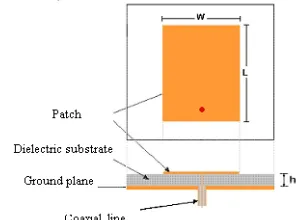
Figure 1 shows the proposed antenna excited by probe coaxial, with W is the patch width and L is the length.
[image:2.612.338.490.426.536.2]The proposed antenna is constructed on one layer substrate and the substrate having a relative permittivityεr= 2.2 (Rogers RT/duroid 5880 (tm)), substrate of thickness h = 0.32 cm and loss tangent tan(δ) = 0.001 . The standard power port of the antenna will be set to 50 Ω.
Figure 1: Geometry of the proposed antenna
4. OPTIMIZATION AND RESULTS
4.1 Optimization of the Dimensions of Patch Antenna
(VSWR), Phase of the reflection coefficient, input impedance, gain and directivity of the proposed antenna.
The main objective of the design is to achieve specific performance characteristics for a desired frequency (3, 55 GHz).
The design of the antenna requires basic calculations for the design, the choice of the structure and simulation enables us to optimize the structure chosen.
The calculation carried out by a numerical code “MATLAB” for determining the geometrical dimensions of the antenna gave the following results: the width of the patch is 33 mm and the length is 27 mm.
[image:3.612.318.522.99.260.2]The use of these dimensions in the design does not achieve a minimum level of reflection coefficient S11 (Figure 2). For this reason, it is necessary to change the width and length of the proposed patch antenna to achieve specific performance characteristics.
Figure 2: Reflection coefficient (S11) as a function of
the frequency of the patch antenna for L = 27 mm & W = 33 mm
Table 1 shows the variations of the width and length of the patch antenna optimized.
Table 1: Optimization of the dimensions of patch antenna
Antenna Width
(mm)
Antenna Length
(mm)
Simulated frequency (GHz)
Return Loss
S11 (dB)
VSWR
31 25 3.50 -10.20 1.89
28 25 3.52 -12.53 1.61
26 25 3.53 -20.47 1.20
25.8 25 3.53 -22.64 1.15
25.6 25 3.54 -26.52 1.09
25.1 24 .9 3.55 -47.23 1
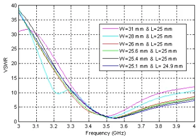
The results of different values in terms of reflection coefficients and voltage standing wave
ratio (VSWR) are respectively represented in figures 3 and 4.
[image:3.612.104.285.343.466.2]
Figure 3: Reflection coefficient for different values of W & L according to the frequency
Figure 3 shows the variation of the parameter S11 for different values of the length and width of the patch antenna according to the frequency. We note that this change gives us an offset parameter S11 as shown in the figure above.
Figure 4: Voltage standing wave ratio (VSWR) for various values of W & L as a function of frequency
From the results of Table 1,the following observations were concluded and summarized in Table 2.
When antenna width decreases, there is a decrease in the reflection coefficient S11 as the VSWR and an increase in the central frequency
When antenna length decreases, there is a decrease in the reflection coefficient S11 as the VSWR , a broadening of the bandwidth and an increase in the central frequency.
Table 2: Resonant frequency and S11 as a function of
[image:3.612.327.524.368.505.2]Antenna Width
(w)
Antenna Length
(L)
Resonant Frequency
(GHz)
Return Loss (S11)
VSWR
Increase Increase Decrease Increase Increase Decrease Decrease Increase Decrease Decrease
4.2 Results of Optimization
4.2.1Reflection coefficient
The reflection coefficient as a function of frequency is given by the following curve:
Figure 5: Reflection coefficient as a function of the frequency of the patch antenna
It was found that the reflection coefficient S11 at the input of the patch antenna reaches the level of -47.23 dB (at a resonance frequency of 3.55 GHz) with a bandwidth of 3.94% (the difference between 3.48 GHz and 3.62 GHz). This means that the reflected power is minimal and therefore it will have a positive impact on increasing the level of the power transmitted by the antenna.
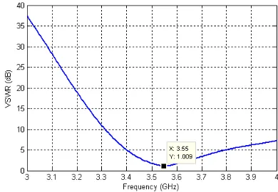
4.2.2 Voltage standing wave ratio
[image:4.612.321.528.171.307.2]The voltage standing wave ratio as a function of frequency is given by the figure 6:
Figure 6: Voltage Standing Wave Ration (VSWR) as a function of frequency
We note that the Voltage standing wave ratio operating at frequency 3.55 GHz is minimum and
equal to 1. This value is used to calculate the bandwidth of the antenna patch.
4.2.3 Phase of the reflection coefficient
The figure 7 shows the phase of reflection coefficient S11 as a function of frequency.
Figure 7: Phase of reflection coefficient S11 as a function
of frequency
It is observed that the phase value of the reflection coefficient S11 is zero at the resonant frequency of 3.55 GHz.
4.2.4 Input impedance of the antenna patch
[image:4.612.323.509.458.581.2]The impedance matching would optimize the transfer of electric power between a source and a load. The following figure shows the layout of the input impedance of our geometry (Figure 8).
Figure 8: Input impedance of the patch antenna as a function of frequency
As shown in Figure 8, the input impedance of the antenna has a resistive part of 49.96 Ω while the reactive part is zero at the operating frequency (3.55 GHz). The antenna is matched to the source.
4.2.5 Gain of the antenna patch
[image:4.612.102.297.532.667.2]allows to immediately reporting the ability of the antenna to radiate evenly over the tape.
Figure 9: Gain pattern of the antenna at 3.55 GHz for .phi = 0° & phi = 90°
We note that the gain of the patch antenna is maximum and its value is 7.49 dB.
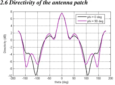
4.2.6 Directivity of the antenna patch
Figure 10: Directivity of the antenna at 3.55 GHz for .phi = 0° & phi = 90°
We note that the directivity of the antenna patch is maximum and its value is 7.53 dB.
5. CONCLUSION
The design and simulation of microstrip patch for WIMAX applications are discussed.
In this work, we obtained a reflection coefficient S11 of -47.23 dB, a standing wave ratio equal to 1, a gain of 7.49 dB, a directivity of 7.53 dB, bandwidth of 3.94% and an efficiency of 99.11% at the resonant frequency of 3.55 GHz. The proposed design has simple design structure and can easily be fabricated at low cost thus being a good solution for many WIMAX applications.
REFERENCES:
[1] R. Garg, P. Bhartia, I. Bahl and A. Ittipiboon, “Microstrip Antenna Design Handbook”, Artech House Antennas & Propagation Library, Nov 2000 .
[2] J.L. Volkais: “Antenna Engineering Handbook”, Mc Graw Hill Companies, 2007. [3] P. Pigin, “Emerging mobile WiMax antenna
technologies”, IET Communication Engineer, October/ November 2006.
[4] Y. Yu, Y. Lee, S. Lee and J. Choi, “A compact internal antenna for wireless USB Dongle application”, in Proc. ICAT 2009, pp1084-1086.
[5] Nazish Irfan, Mustapha C. E. Yagoub, Khelifa Hettak “Design and FDTD Analysis of Single -Band and Dual--Band Antennas for RFID and WiMAX Applications”, Publishers, 2011. [6] R. Dewan, S. K. A. Rahim, S.F. Ausordin, H.
U. Iddi and M.Z.A. Abd. Aziz,” X-Polarization Array Antenna with Parallel Feeding for WiMAX 3.55 GHz Application”, IEEE International RF and Microwave Conference (RFM 2011), 12th - 14th December 2011, Seremban, Malaysia,pp.368-372.
[7] Adnane-Latif,” Design of Miniature Patch Antenna Around the Frequency 3.5 GHz for WIMAX Technology “, IJCSI International Journal of Computer Science Issues, Vol. 9, Issue 1, No 2, January 2012,pp.357-361.
[8] Anamika Singh, Aadesh Arya and Sanjay Sharma,”High Gain of C Shape Slotted Microstrip Patch Antenna for Wireless System”, International Journal of Applied Engineering Research, ISSN 0973-4562 Vol.7 No.11 (2012).
[9] Boutheina Tlili,” Design of Double C-Slot Microstrip Patch Antenna for WiMax Application”IEEE, 2010.
[10] I. J. Bahl and P. Bhartia, Microstrip Antennas, Artech House, Dedham, MA, 1980.
[image:5.612.97.288.321.463.2][12] P. B. Katehi and N. G. Alexopoulos, “On the Modeling of Electromagnetically Coupled Microstrip Antennas-The Printed Strip Dipole,” IEEE Trans. Antennas Propagat., Vol.AP-32, No. 11, pp. 1179–1186, November 1984.
[13] J. R. James and P. S. Hall, Handbook of Microstrip Antennas, Vols. 1 and 2, Peter Peregrinus, London, UK, 1989.
[14] Pozar, “Microstrip Antennas,” Proc. IEEE, Vol. 80, No. 1, pp. 79–81, January 1992.
[15] H. G. Oltman and D. A. Huebner, “Electromagnetically Coupled Microstrip Dipoles,” IEEE Trans. Antennas Propagat., Vol. AP-29, No. 1, pp. 151–157, January 1981. [16] G. Gronau and I. Wolff, “Aperture-Coupling of a Rectangular Microstrip Resonator,” Electronic Letters, Vol. 22, pp. 554–556, May 1986.
[17] Constantine A. Balanis: “Antenna Theory, Analysis and design” (John Wiley & Sons). [18] R. B.Waterhouse, Microstrip Patch Antennas