58
FAULT TEST DEVICE OF ELECTRICAL SYSTEM BASED
ON EMBEDDED EQUIPMENT
1
XIONG YUN, 2YANG XIAOQIANG, 3DUAN ZHUANGZHI AND 4LI NING
1PLA University of Science & Technology, Nanjing, China
2PLA Institute of Engineer Corps, Xuzhou, China
E-mail: 1[email protected] , 2[email protected]
ABSTRACT
The electrical system of the construction machinery usually works on circumstance of high temperature, serious vibration and shock, dust pollution as well as electromagnetic interference, so the electrical system is very likely to go wrong while compared with other systems, for example working attachment, under chassis and so on. In view of this, an advanced fault test device, with application of embedded equipment and virtual technology, is developed in this work. The function and implementation of software are illustrated. The device is composed of PDA, cradle and CF-bus data acquisition card. It can test and diagnose the circuit and electronic component fault. Furthermore it stores the data and upload data to server simultaneously for further diagnosis and processing of repair and maintenance expert. The fault test device may be utilized in fault diagnosis of electrical system and components of engineering vehicles, subsequently improve the maintenance and diagnosis capability for the electrical system.
Keywords: Embedded Equipment, Virtual Instrumentation, Fault Diagnosis, Electrical System.
1. INTRODUCTION
Due to the high technology content, complex structure and operating principle of electrical system of the construction machinery, the traditional testing method is incapable of testing and localizing the fault . These effects may result in the degradation and inefficiency of maintenance and combat support for the engineering vehicles and construction machineries, thus portable fault test device is more and more critical for the demand of combat engineering support. According to statistics, fifty percents to sixty percents sudden and random malfunctions of engineering machinery are concentrated in the electrical equipment, electronic control unit and auxiliary equipment. Yet for these malfunctions, the general use and maintenance unit has significant deficiencies either from the technical data reserves, the maintenance technology training, or from the complete sets of maintenance tools and the rapid detection instrumentation. Therefore we need more support from the manufacturer or the external technology. So far, most units still lack an effective solution. This present condition is clearly unable to satisfy the use and maintenance requirements of the engineering machinery.
Consequently, developing a set of portable electrical system fault diagnosis device has a momentous significance. It can assist maintenance personnel in locating, assembling and disassembling, and renewing the electronic control and electric device of the engineering equipment, thus achieving the rapid detection, maintenance and support.
2. OVERALL DESIGN SCENARIO
59 weight, low energy consumption, high reliability, plug and play, and precise measurement, and also can be programmed by software, thus to calibrate,
analysis, process and record the datas. It is an ideal choice of portable measurement and handheld PDA data recording.
Figure1 System Hardware Block Diagram
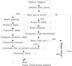
3. FAULT TEST PROCEDURE
In order to facilitate the operation and use of the detector, the detector designed the testing of the electrical control system into two cases. The first case is to measure the important testing points of the various types of electrical control system of engineering machinery. The testing system has put the name of these important points and their correct range of values into the system, and the operator only need to select the measuring points through the drop-down box by using the PDA touchpen, then place the testing instrument pen on the testing point, after that the detector will display the testing result on the interface. The display is achieved by logic lights: the red light indicates that the testing point is not in the correct range and that may have trouble, and the blue light indicates that the testing point is
well. The second case is random measurement: measure every electronic device’s voltage, current and resistance of various types of electrical control system of engineering machinery directly, and then determine the fault positions by gradual sieve method. The testing flow chart is shown in Figure 2.
4. FUNCTION AND SOFTWARE
DEVELOPMENT
System Function. The detector mainly includes four
functions: “Basic Testing”, “Preliminary Diagnosis”, “Data Storage”, and “Data Reading”.
60 control system circuit and electronic components of the engineering machinery.
“Preliminary Diagnosis” is mainly to determine whether the testing points are within the scope of the provisions through the correct values predetermined in the program. Red lights indicate that the testing points may have a problem, and the blue lights indicate that the testing point is normal and the testing can be continued.
“Data Storage” is mainly to save the data into a text file of the PDA, in order to provide data references for the following fault diagnosis and the remote fault diagnosis experts. While running this function, the operator should set the save location and the file name first, otherwise it will prompt an error.
[image:3.612.157.458.234.510.2]“Data Reading” is mainly to read the testing data, including the pre-detection data and the detecting data, which is used to be the quantitative analysis of the fault diagnosis.
Figure 2 Fault Testing Schematic
Software Development. The first step of the
software programming to the detector system is to install LabVIEW PDA Module for PPC, and then the operator can choose the platform that will be running while opening the LabVIEW. The second step is to copy the NI PCMCIA-4050 PDA driver into the Windows folder, so that the system can run well after the NI PCMCIA-4050 inserting into the PDA clip. After the preparative work, the operator can have the development and design of the testing system in the LabVIEW development environment.
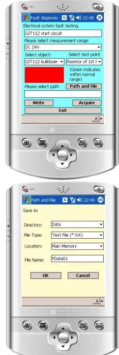
In this paper, we use LabVIEW7.1 development platform, and the main interface is designed to function button and drop-down menu form, and the function modules are achieved by function buttons, which is shown in Figure 4. There are four function buttons: “PATH AND FILE”(Determine the save
location and save file), “WRITE”(Record data), “READ”(Read data), “EXIT”(Exit system). There are three drop-down menus: “SELECT RANGE”, “SELECT MACHINE”, “SELECT TESTING POINT”. Click “PATH AND FILE” menu, and select the save location and the save filename in the pop-up dialog box. Click “WRITE” and “READ” menu will separately pull the recording data sub-window and the reading data sub-sub-window (also known as sub-VI), and when the sub-VI is closed, the main window will reappear.
61 information table, standard data table, diagnosis procedure table, fault symptom and cause table, repair and maintenance of data table etc. The basic information table involves the technical parameters, working performance, operating requirements of electrical system. The standard data table is a storage file of standard working characteristics and failure threshold data of the system. The diagnosis procedure table stores information of fault detection procedure, method and other data. The table of fault symptom and cause contains the conventional fault symptoms and the coresponding causes. And the repair and maintenance data table includes all the information of fault troubleshooting method, parts or subsystem dimension data as well as the repair procedure data etc.
The database files on PDA are stored in format of XML file. XML is Extensible Markup Language. It uses classification document composed of component and property to describe complex structure data. This description format ensures the database document independent of the hardware platform, operating system and development software. Because of the standard architecture and properties, the representation difference of text-language based fault information is easy to be solved. Thus this makes it possible to establish compact and integrated solution with components on various operating platform. The data on database server are converted to XML document by C# progaming language. The general code is illustrated in the following.
SqlConnection conn = new SqlConnection (connstring)//Create connection object
SqlCommand selcmd = new SqlCommand(“SELECT * FROM Table”, conn); //Create SQL command object
SqlDataAdapter da = new
SqlDataAdapter(selcmd); //Create SQL data adapter DataSet ds = new DataSet();//Create data set da.Fill(ds, Table); //Fill data set
ds.WriteXmlSchema(FileName);//Save XSD format file
ds.WriteXml(FileName);//Save XML file
5. APPLICATIONS
Take example for the high-speed excavator of a certain unit, when a machine idling the shaking phenomenon could occur, with the accelerating reaction becoming slowly and the vent-pipe giving off black smoke, and the fault still exists after
restarting. Through checking the machine native state display, we reach the following consensus: the fault phenomenon may be caused by the malfunction of the intake air temperature sensor and the intake air pressure sensor. Under normal circumstances, the resistance value of the
temperature sensor is 2~3 kΩ at 20℃, 1.0~1.8 kΩ
at 40℃, 500~800Ω at 60℃. No.2 terminal voltage
is 4.85~4.95V, and the resistance of No.1 terminal
to No.30 terminal is 0Ω. After the machine starting,
the range of No.2 and No.1 terminal voltage value is between 0.6~3.5V. The pressure sensor voltage of No.12 terminal to No.3 terminal is 5V, No.7 terminal earthing voltage is 4.0~4.5V, and after the machine starting, the range of voltage is changing between 1.0~1.5V.
Figure 3 (A) Main Panel, (B) Saving Data Panel
[image:4.612.356.473.289.637.2]62 testing point” drop-down menu, and the testing points order is: temperature sensor resistance – No.2 terminal voltage –resistance of No.1 terminal to No.30 terminal – No.2 and No.1 terminal voltage– the pressure sensor voltage of No.12 to No.3 terminal – No.7 terminal voltage. Select the measurement points corresponding voltage shelves or the resistance shelves in the “select range” drop-down menu, then place the two detection pens at the both ends of the measuring point, and if the data is a negative value, replace the position of the two detection pens. Check the indicator whether the light is red or green, after noting the result, selects a new measuring point orderly. In Figure 5, it is separately shown detection platform main panel(a), saving data panel(b).
6. CONCLUSIONS
In this work, the fault device for electrical system of construction machinery is described. This device integrates virtual instrumentation technology, embedded technology with the portable electronic equipment. Compared with conventional electronic monitoring device, this parameter recorder has many advantages such as large storage capacity, high work stability, high reliability and friendly operation interface. Some of its benefits are presented as follows:
(1) High precision measurement, fast speed, stable operation and easy operating
The measurement of the platform using NI PCMCIA-4050 is so precise that can be accurate to five decimal places, and the detecting speed is so fast that can detect tens to hundreds times each second. The impedance value of the NI
PCMCIA-4050 is up to 10000MΩ above, so as to the
measurement error is very low, and with the consummate protection circuit it can protect against the damage to the board because of overcurrent, overvoltage and overload, therefore making the board more stable. The alarm setting of the module upper limit and lower limit makes the operation of the PDA electronic manual more simple.
(2) Flexible function and powerful capability This platform not only has all the functions of the digital multimeter, but also can simply analyze, save, read and send the obtained datas by using the advantages of PDA, that make it have a certain ability of circuit diagnosis and signal collection, and provide some quantitative basis for the following fault diagnosis. The design of the distinctive detection clip and testing interface makes the testing platform can be used for the maintenance of
multiform engineering equipment electrical system. Especially, the application of the electronic manual carried on the engineering equipment vehicle or as a module of the electronic manual, can greatly enhance the overall maintenance and diagnostic capabilities of the platform.
REFERENCES
[1]http://www.ech.ee.echz.ch/uploads/tx_ethpublicati ons/bockarjova_powertech03.pdf.
[2] Rasli A Ghani, Azah Mohamed, Hussain Shareef. “ANFIS Approach for Locating Precise Fault Points withCoordinated Geometries in a Test Distribution System” , European Journal of Scientific Research, ISSN 1450-216X Vol.35 No.3 (2009), pp.461-473. [3] Li Xingshan, Zuo Yi, Sun Jie. Auto-testing
System Integration Technique[M].Peking: Electronic Industry Press, 2004.
[4] Guo Yi’an, Wang Xudong, Wang Xuejun. Research of Automobile Fault Diagnosis System Based On CAN BUS [J]. Electronic Science and Technology, 2007,(01).
[5] L.B. JACK, A.K. NANDI. Fault Detection