ISSN: 1992-8645 www.jatit.org E-ISSN: 1817-3195
APPLICATION OF BOILER-PREHEATER FUZZY
COORDINATED CONTROL FOR CLINKER PLANT
1, 2XIANG ZHANG, 1, 3JIDONG LU
1State Key Laboratory of Coal Combustion, Huazhong University of Science and Technology, Wuhan
430074, Hubei, China
2
Guangdong Institute of Metrology, South China National Centre of Metrology, Guangzhou 510405,
Guangdong, China
3School of Electric Power, South China University of Technology, Guangzhou 510641, Guangdong, China
ABSTRACT
A boiler-preheater fuzzy coordinated control system used in new type dry rotary kiln and pure low temperature waste heat recovery power generation has been presented in this paper. Heat of waste gas from cement kiln is recovered by the power generation. Significantly, SP boiler of the power generation recovers heat of the gas from kiln preheater. The temperature of the recovered gas from cement kiln is continuous fluctuant because of severe condition of cement kiln. The fluctuant temperature is unfavorable for power generation. For high efficiency of systems in of cement kiln and waste heat power generation, development and tests of the boiler-preheater fuzzy coordinated control system have been carried out in a cement kiln plant adding low-temperature waste heat power generation in Guangdong, China. The actual application result shown that the boiler-preheater fuzzy coordinated controller is available and efficient.
Keywords: Coordinated Control, Fuzzy Controller, Kiln Preheater, SP Boiler, Clinker
1. INTRODUCTION
New type dry rotary kiln is a facility for new type processing cement, which product cement clinker using raw material. The provide heat in processing is from coal that is fed into rotary kiln and precalciner. The produced exhaust gas in processing is discharge through chimney in both ends of cement rotary kiln. From measuring to the two parts gas, it carried heat that can be recovered. The temperature of gas discharged from kiln head clinker cooler is about from 520K to 820K, and the temperature of gas discharged from kiln end preheater is about from 570K to 650K [1]. Although the cement rotary kiln plant adopt some recovery heat measures, such as: drying coal, drying raw material etc., the 20% to 40% [2] of the energy is lost with the flue gases flowing out preheater and the hot air flowing out clinker cooler, According to energy audit analysis of dry type rotary kiln system[3]. In order to reduce energy consumption, some possible ways to recover the heat losses are introduced and applied, such as: waste heat power generation, supplying hot water [4]. It is proved that approximately 15% of the total
input energy can be recovered in new type dry rotary kiln.
Pure low temperature waste heat power generation is a new technology recovering heat of exhaust gas from new dry cement kiln. The SP boiler recoveries heat of gas from kiln preheater. Because condition of cement kiln is every severe, it is unfavorable for power generation that the temperature of the recovered gas from cement kiln is continuous fluctuant. Only the power generation and kiln are controlled coordinate near design conditions, the product of two systems will become easy to satisfy; otherwise, product of clinker and power generation will go down. For high efficiency and product, effective control measures should be applied.
To improve the control effect, many researchers study the control approaches of clinker rotary kiln [5][6][7] and waste heat captive boiler[8][9].
ISSN: 1992-8645 www.jatit.org E-ISSN: 1817-3195 efficiency, it is necessary to study the relationship
between preheater and SP boiler, and to design a control system for coordinating two production systems [10]. In this paper, a boiler-preheater fuzzy coordinated control system is presented.
2. PROCESS DESCRIPTIONS
2.1 Overall System Of Cement Kiln And Waste Heat Power Generation
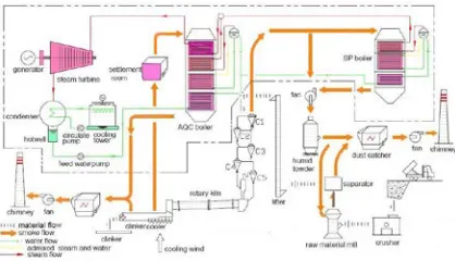
[image:2.612.315.528.276.388.2]The cement clinker plant considered is a 2500TPD dry process rotary kiln production line of cement clinker in Guangdong, China. The plant contain rotary kiln, clinker cooler, precalciner, preheater, coal mill, raw material mill, silos, and so on. The overall system of cement kiln and waste heat power generation is shown as Figure 1.
Figure 1: Overall System of Cement Kiln And Waste Heat Power Generation
2.2 Waste Heat Power Generation System Waste heat source in the cement clinker plant includes the exhaust gas from suspension preheater and the hat air from clinker cooler discharge, which is used separately for pure low temperature waste heat power generation. Because of different temperature levels for the two waste heat sources, waste heat power generation system should designed two boilers to recover waste heat. The first one is called AQC boiler for the preheater exhaust gas, and the other is called SP boiler for the clinker cooler exhaust gas. The two boilers produce over heating stream to drive generators. For drying raw material, the temperature of from SP boiler to raw material mill should be no less than the requested 470K.
In Figure 2, the waste heat power generation system for the considered cement clinker plant is the single pressure waste heat power generation system, which contain AQC boiler, SP boiler, steam tribute, generator, condenser, feed water pump, cooling tower, and so on. Water is fed from deaerator to AQC public economizer by feed water
[image:2.612.91.300.303.423.2]pump. The heated water out public economizer flows into AQC boiler drum and SP boiler economizer. The water is turned to stream in boilers. The two parts stream from two boilers are mixed in AQC boiler mixed stream room. The mixed stream is heated in over high-temperature superheater of AQC boiler and becomes main stream. The main stream flows into the turbine and drives generators. The exhaust steam flowing from turbine to condenser becomes condensation water. The condensation water is pumped into deaerator, and then the feed water from deaerator is pumped into public economizer of AQC boiler. The cycle is finished, and the waste heat is transform electric energy.
Figure 2: Single Pressure Waste Heat Power Generation System
2.3 Analysis Of Control
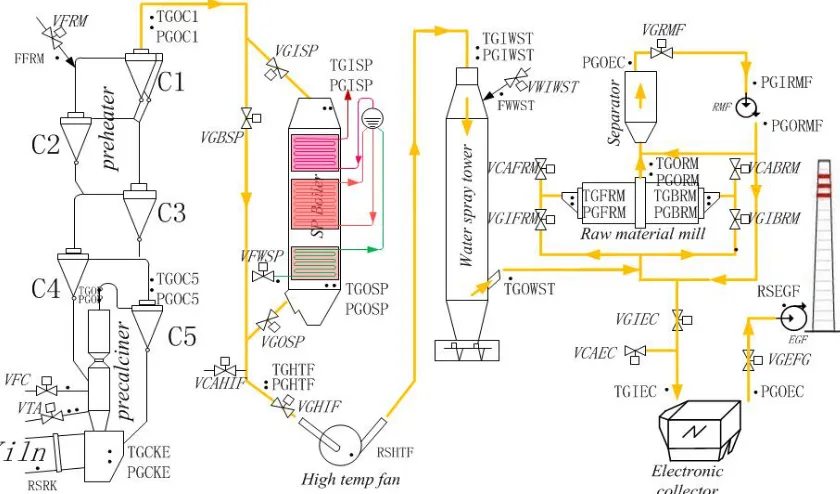
In Figure 3, there are many feeders, fans, valves, thermocouples, manometers and flowmeters Installed in the system.
Three feeders: raw meal feeder (FRM), kiln coal feeder (FKC), precalciner coal feeder (FPC). Fans: high temperature fan (HIF), exhaust gas fan (EGF), raw meal system fan (RMF).
Valves: cold air inlet valve of raw meal mill front end, gas inlet valve of raw meal mill front end, cold air inlet valve of raw meal mill back end, gas inlet valve of raw meal mill back end, gas inlet valve of high temperature fan, cold air inlet valve of high temperature fan, gas inlet valve of Electronic collector, cold air inlet valve of Electronic collector, gas inlet valve of raw meal mill fan, gas inlet valve of exhaust gas fan, gas inlet valve of AQC boiler, gas outlet valve of AQC boiler, gas by-pass valve of AQC boiler, raw meal feeder, valve of fed raw meal, valve of fed coal.
ISSN: 1992-8645 www.jatit.org E-ISSN: 1817-3195 temperature of gas into high temperature fan
(TGHTF), temperature of gas into water spray tower (TGIWST), temperature of gas out of water spray tower (TGOWST), temperature of gas in front end of raw meal mill (TGFRM), temperature of gas in back end of raw meal mill (TGBRM), temperature of gas out of raw meal mill (TGORM), temperature of gas into Electronic collector (TGIEC).
Manometers: pressure of gas in chamber at kiln back end (PGCKE), pressure of gas out of precalciner (PGOP), pressure of gas out of 5-stage cyclone pre-heater (PGOC5), pressure of gas out of 1-stage cyclone pre-heater (PGOC1), pressure of gas into SP boiler (PGISP), pressure of gas out SP boiler (PGOSP), pressure of gas into high
temperature fan (PGHTF), pressure of gas into water spray tower (PGIWST), pressure of gas in front end of raw meal mill (PGFRM), pressure of gas in back end of raw meal mill (PGBRM), pressure of gas out of raw meal mill (PGORM), pressure of gas out of Electronic collector (PGOEC), pressure of gas into raw meal mill fan (PGIRMF), pressure of gas out of raw meal mill fan (PGORMF), pressure of gas out of Electronic collector (PGOEC).
[image:3.612.98.518.282.529.2]Flowmeters: feed flow of coal into kiln (FFCK), feed flow of coal into precalciner (FFCP), feed flow of raw meal into preheater (FFRM), feed flow of water into SP boiler (FFWSP).
Figure 3: Valve and Measuring Point Of Control Process
2.4 Control Objective
1. Temperature
of gas in chamber at kiln back
end 1220~1370K
2. Temperature of gas out of precalciner 1120~1170K
3. Temperature
of
gas out of C4 1070~1150K 4. Temperatureof gas
out of C1 590~620K5. Temperature of gas into high temperature fan 590K
6. Temperature of gas in front end of raw meal mill 470~520K
7. Temperature of gas in back end of raw meal mill 8. Temperature of gas out of raw meal mill
350~380K
9. Pressure of gas in kiln head hood -20~-60Pa 10. Pressure of gas in chamber at kiln back end
-200~-400Pa
11. Pressure of gas in front end of raw meal mill -600Pa
12. Pressure of gas in back end of raw meal mill -600Pa
13. Pressure of gas into raw meal mill fan 7500Pa 14. Pressure of gas out of raw meal mill fan
0~500Pa
ISSN: 1992-8645 www.jatit.org E-ISSN: 1817-3195 3. COORDINATED CONTROL SYSTEM
DEVELOPMENT
3.1 Operating Experience Of Operator
From the above discussion of the process, it is obvious that the temperature of gas out of C1 is the main factor to affect the heat consumption of clinker production and thermal efficiency of SP boiler. If the temperature of gas out of C1 is too high, the heat consumption of clinker production and thermal efficiency of SP boiler are increased; else if the temperature is too low, the productivity of clinker and thermal efficiency of SP boiler are reduced, and the heat consumption of clinker production is increased also. So, appropriately controlled temperature of gas out of C1 is the main factor for clinker production and power generation.
3.2 Coordinated Control Strategy
The valves 2123~2126 (VGIFRM, VCAFRM, VGIBRM, VCABRM) are regulated to change the flow rate of hot gas and cold air according to the temperature of gas into raw meal mill and the temperature of gas out of raw meal mill.
The water inlet valve of water spray tower (VWIWST) is regulated to change the temperature of gas out of water spray tower.
The valve 2209 (VCAEC) is regulated to change the temperature of gas into electronic collector.
The raw meal feeder is regulated to change the feed flow of raw meal according to temperature of gas out of C1 and the rotate speed of rotary kiln.
The valve of fed coal into precalciner is regulated to change the feed flow of coal into precalciner according to the temperature of the temperature of gas out of 5-stage cyclone pre-heater and the temperature of gas out of precalciner.
The VGISP, VGOSP and VGBSP are regulated to change the flow of gas through SP boiler according to the temperature of gas out of 1-stage cyclone pre-heater and the temperature of gas into high temperature fan.
The VCAHTF is regulated to change the flow of cold air to reduce the temperature of gas into high temperature fan.
The VFWSP is regulated to change the flow of feed water according to the drum water level.
When the running parameters of rotary kiln system are normal, the raw meal feeder is regulated to change the feed flow of raw meal according to temperature of gas out of C1 and the rotate speed of rotary kiln. The higher the temperature is, the bigger the feed flow is. Similarly, the higher the rotate speed is, the bigger the feed flow is. So long as the running parameters of rotary kiln system are
abnormal, such as: the pressure of gas out of every stage cyclone pre-heater, the pressure of gas out of precalciner, etc. the raw meal feeder is turned off firstly. The steady temperature of gas out of C1 is propitious to operation of cement clinker production and SP boiler.
In cement clinker production line, the temperature of gas out of C1 is about 620K, but the temperature of gas into raw meal mill is about 490K only. The heat of gas is lost by spraying water and mixing cold air without waste heat recovery. Now, the SP boiler of waste heat recovery power generation recovers the loss heat. The temperature of gas out of SP boiler should be controlled for drying of raw meal. The nearer the temperature of gas out of SP boiler gets to the requested temperature of dry raw meal, the less the spraying water is and the more the recovered heat is. Another part of gas out of C1 flows through by-pass pipe of SP boiler. Two parts of gas is mixed before high temperature fan. If the temperature of the mixed gas is satisfactory for drying raw meal, it is send to raw meal mill without spraying water in water spraying tower. Spraying water is reduced, and much more waste heat is recovered by SP boiler. So according to monitoring values of the temperature of gas out of SP boiler, the temperature of gas into high temperature fan, the temperature of gas into SP boiler, the controller regulates three valve: gas inlet valve of SP boiler, gas outlet valve of SP boiler, gas by-pass valve of SP boiler. If raw meal mill is stopped, the setting temperature of gas out of SP boiler will set low temperature range and much more waste heat of gas will be recovered.
4. FUZZY CONTROLLER
4.1 Fuzzy Control Strategy
According to the above analysis of control process and coordinated control strategy, the control scheme was made. It can be divided into seven parts: controlling raw meal feeder, controlling precalciner coal feeder, controlling high temperature fan speed, controlling SP boiler gas flow rate, controlling water flow of water spray tower, controlling cold air inlet valve of raw meal mill back end, and controlling SP boiler feed water flow. The introduction of these schemes is expatiated as follows.
ISSN: 1992-8645 www.jatit.org E-ISSN: 1817-3195 and average speed (RSERK). The output of
controller is setting feed flow of raw meal into preheater (SFFRM). And the inputs of controller Ⅱ are temperature error of gas out of 1-stage cyclone pre-heater between measured and values (TEGC1) and change rate of TEGC1 (CTEGC1). The output is setting correct value of SFFRM (SFFRM2). The addition of the two controller outputs is used to control raw meal feeder. The control logic is shown as Figure 4.
[image:5.612.315.523.79.146.2]RSRK Fuzzy Controller Ⅰ Fuzzy Controller Ⅱ SFFRM STGC1 Raw meal feeder + + -TGC1 ARSRK
Figure 4: Raw Meal Feeder Control Block Diagram
The second control strategy for precalciner coal feeder is implemented by a fuzzy controller. The controller has three inputs and one output. The inputs of controller are temperature error of gas out of 5-stage cyclone pre-heater between measurement and set values (TEGOC5), temperature error of gas out of precalciner between measurement and set values (TEGOP), and change rate of TEGOP (CTEGOP). And the output is setting feed flow of precalciner coal (SFFPC). The control logic is shown as Figure 5.
[image:5.612.94.296.214.299.2]Fuzzy Controller STGOP Feeder regulator precalciner coal feeder STGOC5 Rotary Kiln System Temperature transmitter Temperature transmitter TGOC5 TGOP
Figure 5: Precalciner Coal Feeder Control Block Diagram
The third control strategy for high temperature fan speed is implemented by a fuzzy controller. The controller has four inputs and three outputs. The inputs of controller are pressure error of gas outlet of C1 between measurement and set values (PEGOC1), minimum value of PVGISP and PVGOSP (mPVGSP), Gas by-pass valve of SP boiler (VGBSP).The outputs of controller are setting rotate speed of high temperature fan (SRSHTF), setting gas inlet valve of SP boiler (SVGISP), setting gas by-pass valve of SP boiler (SVGBSP). The control logic is shown as Figure 6.
[image:5.612.316.520.336.417.2]Fu zz y Co PGOC1 Regulator High temperature fan frequency changer Rotate speed transmitter -PVGISP PVGOSP MinmPVGSP PVGBSP SVGBSP SVGISP SRSHTF RSHTF
Figure 6: High Temperature Fan Control Block Diagram
The fourth control strategy for SP boiler Gas flow can be put into practice by a fuzzy controller. it is a very complex controller because the controller has four inputs and three outputs. The inputs of controller are temperature error of gas outlet of SP boiler between measurement and set values (TEGOSP), change rate of TEGOSP (CTEGOSP), temperature of gas into SP boiler (TGISP), and temperature of gas into high temperature fan (TGHTF). The output is setting gas inlet valve of SP boiler (SVGISP), setting gas outlet valve of SP boiler (SVGOSP), and setting gas by-pass valve of SP boiler (SVGBSP). The control logic is shown as Figure 7.
Fu zz y Co nt ro STGOSP Regulator Gas inlet valve of SP boiler (VGISP) TGHTF SVGOSP SVGBSP SVGISP Regulator Gas outlet valve of SP boiler (VGOSP) TGISP SP b oi le r & by -pa ss Temperature transmitter Temperature transmitter Temperature transmitter TGOSP Regulator Gas by-pass valve of SP boiler (VGBSP)
Figure 7: SP Boiler Gas Valves Control Block Diagram
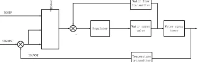
The fifth controller strategy for water flow of water spray tower is implemented by a fuzzy controller. The controller has three inputs and one output. The inputs of controller are temperature of gas into high temperature fan (TGHTF), temperature error of gas out of water spray tower between measurement and set values (TEGOWST), and change rate of TEGOWST (CTEGOWST). The output of controller is setting water flow of water spray tower (SWFWST). The control logic is shown as Figure 8.
Fu zz y Co nt ro STGOWST
Regulator Water spray valve Water flow transmitter -TGHTF Water spray tower Temperature transmitter TGOWST
Figure 8: Water Spray Control Block Diagram
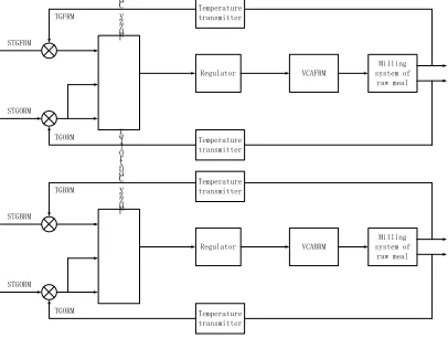
[image:5.612.93.295.455.554.2] [image:5.612.317.519.572.636.2]ISSN: 1992-8645 www.jatit.org E-ISSN: 1817-3195 Electronic collector between measurement and set
[image:6.612.93.296.269.422.2]values (TEGIEC), and change rate of TEGIEC (CTEGIEC). The output of controller is setting cold air inlet valve of raw meal mill front end (SVCAFRM). The controller Ⅱ has three inputs and one output. The inputs of controller are temperature error of gas in back end of raw meal mill between measurement and set values (TEGBRM), temperature error of gas into Electronic collector between measurement and set values (TEGIEC), and change rate of TEGIEC (CTEGIEC). The output of controller is setting cold air inlet valve of raw meal mill back end (SVCABRM). The control logic is shown as Figure 9. Fu zz y Co nt ro STGORM Regulator VCAFRM STGFRM Milling system of raw meal Temperature transmitter Temperature transmitter TGORM TGFRM Fu zz y Co nt ro ll er STGORM Regulator VCABRM STGBRM Milling system of raw meal Temperature transmitter Temperature transmitter TGORM TGBRM
Figure 9: Raw Meal Milling System Gas Temperature Control Block Diagram
The seventh controller strategy for feed water flow of towers boiler is implemented by a fuzzy controller and two PID controllers. The fuzzy controller has three inputs and three outputs. The inputs of controller are temperature of gas into SP boiler (TGISP), temperature of gas out SP boiler (TGOSP), and temperature error of feed water of SP boiler between measurement and set values (TEFWSP). The outputs of controller are setting correct of feed water flow (SCFWF), gas inlet valve of SP boiler (VGISP), and gas outlet valve of SP boiler (VGOSP). The control logic is shown as Figure 10. Fu zz y Co nt ro ll er SDWL STFWSP
PID Ⅰ VFWSP
Feed water flow transmitter -+ TGISP SP boiler Temperature transmitter Drum water level transmitter
PID Ⅱ
Drum water level TGOSP VGISP VGOSP TFWSP DWL SCFWF TFWSP
Figure 10: SP Boiler Feed Water Flow Control Block Diagram
4.2 Fuzzy Controllers Design
The boiler-preheater fuzzy coordinated control system consists eight parts: raw meal feeder controller Ⅰ & Ⅱ, precalciner coal feeder controller, high temperature fan controller, SP boiler gas valves controller, water spray controller, VCABRM controller, and SP boiler feed water flow controller.
(1) Raw meal feeder controller Ⅰ & Ⅱ
The fuzzy sets of variables are defined in Table 1 [11][12][13]. The roles are shown in Table 2.
Table 1 Fuzzy Variables Of Raw Meal Feeder Controller A. Controller Ⅰ
Variables Basic Range Range Fuzzy sets
RSRK [0r/min, 5r/min] [-5,+5] {TF,SF,O,SS,TS}
RSERK [0r/min, 5r/min] [-5,+5] {TF,SF,O,SS,TS}
SFFRM [0kg/s,120kg/s] [-5,+5] {TB,B,O,S,TS}
B. Controller Ⅱ
Variables Basic Range Range Fuzzy sets
TEGC1 [-50K,+50K] [-5,+5] {TF,SF,O,SS,TS}
CTEGC1 [-15K/min,+15K/min] [-5,+5] {TF,SF,O,SS,TS}
SFFRM2 [-15kg/s,15kg/s] [-5,+5] {TB,B,O,S,TS}
Table 2 Control Rule Of Raw Meal Feeder Controller For Controller Ⅰ
SFFRM RSRK
TF SF O SS TS
RSERK
TB TB B O S TS
B B O O S TS
B B O O TS TS
SS O O S TS TS
TS O S TS TS TS
(2) Precalciner coal feeder controller
The fuzzy sets of variables are defined in Table 3 [11][12][13]. One part of the roles (for CTEGOP=O) is shown in Table 4.
Table 3 Fuzzy Variables Of Precalciner Coal Feeder Controller
Variables Basic Range Range Fuzzy sets
TEGOC5 [-20K,20K] [-5,+5] {TF,SF,O,SS,TS}
TEGOP [-20K,+20K] [-5,+5] {TF,SF,O,SS,TS}
CTEGOP [-6K/min,+6K/min] [-3,+3] {B,O,S}
SFFPC [0kg/s,15kg/s] [-5,+5] {TB,B,O,S,TS}
Table 4 Control Rule Of Precalciner Coal Feeder Controller For CTEGOP=O
SFFPC TEGOC5
TF SF O SS TS
TEGOP
TB TB B O S TS
SF B O O S TS
B B O O TS TS
B O O S TS TS
ISSN: 1992-8645 www.jatit.org E-ISSN: 1817-3195 (3) High temperature fan controller
[image:7.612.312.523.113.301.2]The fuzzy sets of variables are defined in Table 5 [11][12][13]. One part of the roles (for PEGOC1=O & VGBSP=O) is shown in Table 6.
Table 5 Fuzzy Variables Of High Temperature Fan Controller
Variables Basic Range Range Fuzzy sets
PGOC1 [0Pa,7500Pa] [-5,+5] {TF,SF,O,SS,TS}
PEGOC1 [-100Pa/s,+100Pa/s] [-3,+3] {F,O,S}
mPVGSP [0%,100%] [-5,+5] {TF,SF,O,SS,TS}
PVGBSP [0%,100%] [-3,+3] {B,O,S}
SRSHTF [0,960r/min] [-5,+5] {TF,SF,O,SS,TS}
SVGISP [0%,100%] [-5,+5] {TF,SF,O,SS,TS}
SVGBSP [0%,100%] [-5,+5] {TF,SF,O,SS,TS}
Table 6 Control Rule Of High Temperature Fan Controller For PEGOC1=O & VGBSP=O
SRSHTF PGOC1
SVGISP
TB B O L TL
SVGBSP
mPVGSP TB
O O O SF O
O O O SF O
SF O SS SS O
B
O SF SF SF SF
O SF SF SF SF
SS SS TS TS O
O
SF SF TF TF SF
SF SF TF TF SF
SS TS TS TS SS
L
SF SF TF SF SF
SF SF TF SF SF
SS SS TS SS O
TL
TF TF TF SF O
TF TF TF SF O
TS SS SS O SF
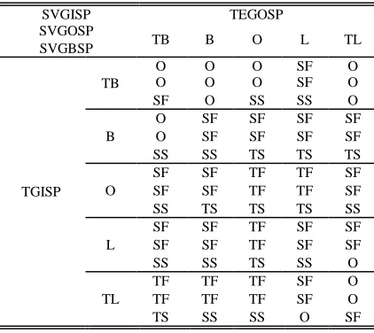
(4) SP boiler gas valves controller
[image:7.612.94.293.169.250.2]The fuzzy sets of variables are defined in Table 7 [11][12][13]. One part of the roles (for CTEGOSP=O & TGHTF=O) is shown in Table 8.
Table 7 Fuzzy Variables Of SP Boiler Gas Valves Controller
Variables Basic Range Range Fuzzy sets
TEGOSP [-100K,+100K] [-5,+5] {TF,SF,O,SS,TS}
CTEGOSP [-5K/s,+5K/s] [-3,+3] {TF,SF,O,SS,TS}
TGISP [420K,650K] [-5,+5] {TF,SF,O,SS,TS}
TGHTF [420K,650K] [-3,+3] {TF,SF,O,SS,TS}
SVGISP [0%, 100%] [-5,+5] {TF,SF,O,SS,TS}
SVGOSP [0%, 100%] [-5,+5] {TF,SF,O,SS,TS}
SVGBSP [0%, 100%] [-5,+5] {TF,SF,O,SS,TS}
Table 8 Control Rule Of SP Boiler Gas Valves Controller For CTEGOSP=O & TGHTF=O
SVGISP TEGOSP
SVGOSP
TB B O L TL
SVGBSP
TGISP TB
O O O SF O
O O O SF O
SF O SS SS O
B
O SF SF SF SF
O SF SF SF SF
SS SS TS TS TS
O
SF SF TF TF SF
SF SF TF TF SF
SS TS TS TS SS
L
SF SF TF SF SF
SF SF TF SF SF
SS SS TS SS O
TL
TF TF TF SF O
TF TF TF SF O
TS SS SS O SF
(5) Water spray controller
The fuzzy sets of variables are defined in Table 9 [11][12][13]. One part of the roles (for CTEGOWST=O) is shown in Table 10.
Table 9 Fuzzy Variables Of Water Spray Controller
Variables Basic Range Range Fuzzy sets
TGHTF [420K,650K] [-5,+5] {TF,SF,O,SS,TS}
TEGOWST [400K,570K] [-5,+5] {TF,SF,O,SS,TS}
CTEGOWST [-6K/s,+6K/s] [-3,+3] {F,O,S}
SWFWST [0%,100%] [-5,+5] {TF,SF,O,SS,TS}
Table 10 Control Rule Of Water Spray Controller For CTEGOWST=O
SWFWST TGHTF
TF SF O SS TS
TEGOWST
TF TB B O S TS
SF B O O S TS
O B O O TS TS
SS O O S TS TS
TS O S TS TS TS
(6) Raw meal milling system gas temperature controller
The fuzzy sets of variables are defined in Table 11 [11][12][13]. One part of the roles (for CTEGIEC=O) is shown in Table 12.
Table 11 Fuzzy Variables Of Raw Meal Milling System Gas Temperature Controller
A. VCAFRM
Variables Basic Range Range Fuzzy sets
TEGFRM [-150K,+150K] [-5,+5] {TF,SF,O,SS,TS}
TEGIEC [-50K,50K] [-5,+5] {TF,SF,O,SS,TS}
CTEGIEC [-3K/s,+3K/s] [-5,+5] {TF,SF,O,SS,TS}
[image:7.612.99.290.555.634.2]ISSN: 1992-8645 www.jatit.org E-ISSN: 1817-3195 B. Vcabrm
Variables Basic Range Range Fuzzy sets
TEGBRM [-140K, +140K] [-5,+5] {TF,SF,O,SS,TS}
TEGIEC [-50K,50K] [-5,+5] {TF,SF,O,SS,TS}
CTEGIEC [-3K/s,+3K/s] [-3,+3] {F,O,S}
SVCABRM [0%, 100%] [-5,+5] {TF,SF,O,SS,TS}
Table 12 Control Rule Of VCABRM Controller For CTEGIEC=O
SVCABRM TEGBRM
TF SF O SS TS
TEGIEC
TF SF SF O SS TS
SF SF O O SS TS
O SF O O TS TS
SS O O S TS TS
TS O S TS TS TS
(7) SP boiler feed water flow controller
The fuzzy sets of variables are defined in Table 13 [11][12][13]. One part of the roles (for TGISP=O) is shown in Table 14.
Table 13 Fuzzy Variables Of SP Boiler Feed Water Flow Controller
Variables Basic Range Range Fuzzy sets
TGISP [420K,650K] [-3,+3] {F,O,S}
TGOSP [420K,520K] [-5,+5] {TF,SF,O,SS,TS}
TEFWSP [-100K,+100K] [-5,+5] {TF,SF,O,SS,TS}
SCFWF [0%, 100%] [-5,+5] {TF,SF,O,SS,TS}
SVGISP2 [0%, 100%] [-5,+5] {TF,SF,O,SS,TS}
SVGOSP2 [0%, 100%] [-5,+5] {TF,SF,O,SS,TS}
Table 14 Control Rule Of SP Boiler Feed Water Flow Controller For TGISP=O
SCFWF TGOSP
SVGISP2
TB B O L TL
SVGOSP2
TEFWSP TB
O O O SF O
O O O SF O
SF O SS SS O
B
O SF SF SF SF
O SF SF SF SF
SS SS TS TS O
O
SF SF TF TF SF
SF SF TF TF SF
SS TS TS TS SS
L
SF SF TF SF SF
SF SF TF SF SF
SS SS TS SS O
TL
TF TF TF SF O
TF TF SF O O
TS SS O O SF
5. APPLICATION RESULTS
The fuzzy coordinated control system has been applied in a cement plant with pure low temperature waste heat power generation in Guangdong, China. The plant was operated respectively under conventional control mode and
fuzzy coordinated control mode for 72 hours. The operating data was recorded every 24 seconds, and processed and analyzed. In this period, some boundary conditions under conventional control are substantially the same as those under fuzzy coordinated control.
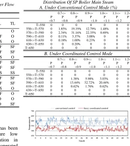
[image:8.612.319.515.212.393.2]The comparison results of SP boiler running in the fuzzy coordinated control mode and conventional control mode are shown as Figure 11 to Figure 13, and in Table 15.
[image:8.612.83.528.320.708.2]Figure 11: Main Steam Temperature Of SP Boiler (TMSP)
Figure 12: Main Steam Pressure Of SP Boiler (PMSP)
Table 15 Temperature Distribution And Pressure Distribution Of SP Boiler Main Steam A. Under Conventional Control Mode (%)
P <0.7
0.7<= P <0.8
0.8<= P
<0.9 0.9<=
P <1.0
1.0<= P <1.1
1.1<= P <1.2
1.2< P
T<550 0 0 0 0 0 0 0
550<=T<570 0 1.85% 19.19% 12.79% 1.48% 0 0
570<=T<590 0 2.34% 31.16% 22.35% 0.69% 0 0
590<=T<610 0 0.11% 3.37% 3.08% 0 0 0
610<=T<630 0 0.18% 1.00% 0.23% 0 0 0
630<=T<650 0 0 0.20% 0 0 0 0
T>650 0 0 0 0 0 0 0
B. Under Coordinated Control Mode
P <0.7
0.7<= P <0.8
0.8<= P
<0.9 0.9<=
P <1.0
1.0<= P
<1.1 1.1<=
P <1.2
1.2< P
T<550 0 0 0 0 0 0 0
550<=T<570 0 0 0 0 0 0 0
570<=T<590 0 0 1.38% 5.98% 3.03% 0 0
590<=T<610 0 0 13.44% 52.72% 20.44% 0 0
610<=T<630 0 0 0.62% 1.76% 0.62% 0 0
630<=T<650 0 0 0 0 0 0 0
[image:8.612.264.519.430.716.2]T>650 0 0 0 0 0 0 0
ISSN: 1992-8645 www.jatit.org E-ISSN: 1817-3195 In Figure 11 and Figure 12, the main steam
temperature and pressure of SP boiler operating under the fuzzy coordinated control are higher than that under conventional control in most of the operating time, and time averaged values under the fuzzy coordinated control are higher than that under conventional control.
As shown in Fig -, the temperature of air flowing into SP boiler under the fuzzy coordinated control is higher than that under conventional control for most of the time according to the temperature of air flowing into AQC boiler running in the fuzzy coordinated control and under conventional control for 72 hours. And the time averaged temperature under the fuzzy coordinated control is higher than that under conventional control. The temperature difference between maximum value and minimum value under the fuzzy coordinated control is smaller than that under conventional control.
In Table 15, it is shows that statistical results of operating data. The results show that the temperature range and pressure range of AQC boiler main steam under the fuzzy coordinated control are better than that under conventional control. The main steam temperature is almost in the range of 0K to 0K, and the main steam pressure is almost in the range of 0.8MPa to 1.1MPa from the Table 1-b under fuzzy coordinated control, which is closer to the standard running conditions of SP boiler than that under conventional control.
Figure 13 shows that the temperature of gas into high temperature fan (TGHTF) under the fuzzy coordinated control is almost in the range of 500K to 540K. It shows that the waste heat of gas is recovered just right. The TGHTF with the conventional control fluctuates within a wide range. Higher temperature of gas into high temperature fan means waste heat is not recovered completely. It will still need to spray cooling in water spray tower for drying raw meal. Similarly, the low temperature of gas into high temperature fan results that the raw material cannot dry.
6. CONCLUSIONS
In this paper, the boiler-preheater fuzzy coordinated control system was devised and designed. The key technology of the system is some controllers based on fuzzy control theory. The controllers show advantages over conventional control mode. Control actions on the SP boiler have been defined in the system. The system has been applied in a cement plant with pure low temperature waste heat power generation in China. The plant was operated respectively under
conventional control mode and fuzzy coordinated control mode for 72 hours. The application results show that the control effect of SP boiler under the fuzzy coordinated control system is superior to that under conventional controller. In most operating conditions, the fuzzy controllers can bring the TGHTF to the ideal level and exhibit high reliability and efficiency.
ACKNOWLEDGEMENTS
A science and technology major project (2008A080800023) and Sci.-tech. special researcher Project (2009B090600059) supported by Guangdong Provincial Department of Science and Technology in China. The authors wish to express thanks to engineers Dongyi Su, Zhixing Zhao, Yongjun Xu, Qile Luo, and Hong Liang for suggestions and for providing test conditions.
REFRENCES:
[1] S. Khurana, R. Banerjee, U. Gaitonde, “Energy balance and cogeneration for a cement plant”, Applied Thermal Engineering, Vol. 22, No. 5, 2002, pp. 485-494.
[2] N.A. Madlool, R. Saidur, N.A. Rahim etc., “An exergy analysis for cement industries- An overview”, Renewable and Sustainable Energy Reviews, Vol. 16, No. 1, 2012, pp. 921-932.
[3] T. Engin, V. Ari, “Energy auditing and recovery for dry type cement rotary kiln systems--A case study”, Energy Conversion and Management, Vol. 46, No. 4, 2005, pp. 551-562.
[4] J. Wang, Y. Dai, L. Gao, “Exergy analyses and parametric optimizations for different cogeneration power plants in cement industry”. Applied Energy, Vol. 86, No. 6, 2009, pp. 941-948.
[5] K.S. Stadler, J. Poland, E. Gallestey, “Model predictive control of a rotary cement kiln”, Control Engineering Practice, Vol. 19, No. 1, 2011, pp. 1-9.
[6] L. Keviczky, J. Hetthessy, M. Hilger, J. Kolostori, “Self-Tuning Adaptive Control of Cement Raw Material Blending”, Automatica, Vol. 14, No. 6, 1978, pp. 525-532.
[7] A.N.I. Wardana, “PID-Fuzzy controller for grate cooler in cement plant”. 5th ASCC Proc.,
ISSN: 1992-8645 www.jatit.org E-ISSN: 1817-3195 [8] X. Wang, C. Wang, P. Li, “Distributed
Control System of Pure Low Temperature Waste Heat Power Generation Plant in Cement Industry”, Control Engineering of China, Vol. 13, No. , 2006, pp. 23-26.
[9] P. Li, Z. G. Yuan, “Application of DCS and Fuzzy Control Technology in Surplus Heat Power Generation of Cement Factory”, Journal of Jinan University (Sci. & Tech.), Vol. 20, No. 4, 2006, pp. 322-325.
[10] X. Zhang, J. Lu, “Fuzzy control for heat recovery systems of cement clinker cooler”, Journal of Theoretical and Applied Information Technology, Vol. 42, No. 2, 2012, pp. 182-190.
[11] K. S. Ray, “Analysis, Design, Implementation and Critical Appreciation of Fuzzy Logic Controller”, Intelligent Systems, Control and Automation: Science and Engineering. Vol. 11, No. 3, 1994, pp. 199-275.
[12] K.J. Astron, T. Hagglund, “PID controllers: theory, design and tuning”, 2nd Edition. Research triangle park, NC: Instrument Society of America, 1995:120-200.