UAV Flight Path Control Using Contraction-Based
Backstepping Control
Tan Chun Kiat
1, Hungsun Son
1, Paw Yew Chai
21School of Mechanical and Aerospace Engineering, Nanyang Technological University, Singapore 2DSO National Laboratories, Singapore
Email: [email protected], [email protected], [email protected]
Received 2013
ABSTRACT
In this paper, a contraction-based backstepping nonlinear control technique was proposed. The proposed controller syn-thesis technique utilizes both the recursive nature of backstepping control and of contraction analysis. This approach results in a contracting closed-loop dynamics, with exponential stability. The use of the hierarchical contraction form in the control problem formulation also results in the exponential convergence of controlled variables and can be easily applied to non-autonomous systems. A flight path angle controller was synthesized and simulated using the proposed technique to demonstrate the exponential convergence achieved by the backstepping controller design.
Keywords: Backstepping; Contraction Theory
1. Introduction
In recent years, missions performed by unmanned aerial vehicle (UAV) has increasingly emphasized on high agility and maneuverability. An example is the tailsitter UAV [1,2] which performs maneuver that covers a large pitch angle. These maneuvers typically require the UAVs to operate outside their linear operating regime, and results in nonlinear flight dynamics characteristics. Nonlinear control techniques, such as backstepping control, were developed to control and improve the performance of such UAVs [3-8].
The stability criterion for traditional backstepping control makes use of the Lyapunov stability theory [3-8]. However, the Lyapunov stability theory often result in complex Lyapunov control function and requires the knowledge of an equilibrium point or trajectory. This often hinders controller synthesis for trajectory tracking control as the equilibrium trajectory is often unknown and the system is often non-autonomous.
The contraction theory [9,10] is a nonlinear stability theory and was applied to control formulation in several instances [11,12]. Stability in contraction theory is de-scribed as the diminishing of the effects from any per-turbation to any trajectory in the state space. The con-traction theory can be easily applied to non-autonomous systems without any added mathematical complexity and does not require the knowledge of any equilibrium point or trajectory. The contraction theory also provided a stronger form of stability as compared to Lyapunov
sta-bility theory which can thus be applied to systems that require fast convergence.
The use of contraction theory as the stability criteria in backstepping control was introduced by Jouffryo [13] with the use of standard contraction form in backstepping control and later by Sharma et al. [14] and Zamani et al. [15]. Standard contraction forms refer to the arrange-ment/ connections of contracting subsystems to form a global contracting system. The contraction form used by [13-15] belongs to the feedback interconnection form [9]. In this paper, a hierarchical form [9] was used for the backstepping controller synthesis. This hierarchical form formulation, which was not commonly found in litera-tures, provided the basis for a subsystem level control. In this way, the backstepping control law can be designed for each subsystem recursively and satisfies global sys-tem contraction conditions with exponential convergence. Different from the feedback interconnection form used by [13-15], the hierarchical form also results in the ex-ponential convergence of individual controlled variables. The proposed controller synthesis technique will be ap-plied to a flight path angle control of a generic UAV.
2. Contraction-Based Backstepping
This section provides the formulation of the contrac-tion-based backstepping control.
2.1. Contraction Theory
The contraction theory is a stability tool for examining the stability of trajectories in the state space. According to contraction theory, a trajectory is stable if it “forgets” the effects from perturbations to that trajectory.
Consider a nonlinear system, x f x=
( )
,t , wheren
∈
x is the state of the system and t is the time. By using the concept of virtual displacement on trajectories, the virtual dynamics can be written as
( )
,tδ =∂ δ
∂
f x
x x
x
(1)
where δx is the virtual displacement of the trajectory.
We can further describe the time variation of δxTδx as
(
T)
T( )
,t .d
dt δ δ δ δ
∂ =
∂
f x
x x x x
x (2)
Here, δxTδx represents the squared distance between infi-nitesimally close trajectories. If the Jacobian, ∂f x
( )
, / ,t ∂x is uniformly negative definite, then the squared distance between trajectories reduces exponentially to zero. Hence, a trajectory is stable as neighboring trajectories con-verges into each other. The state space region where the Jacobian is uniformly negative definite is known as the contraction region.2.2. Hierarchical Connection Structure
Contraction results can also be extended to different sys-tem connections. Contracting subsyssys-tems can be con-nected in different ways to obtain a globally contracting system. In this way, we can prove global contraction by examining the contraction behavior of smaller subsys-tems. The system that will be used in this paper is the hierarchical combination, which resemblances the series connection.
A system with a virtual dynamics of the form
1 11 1
2 21 22 2 0
d dt
δ δ
δ δ
=
x F x
x F F x (3)
is known as the hierarchical combination. The system will be converging if the submatrices F11 and F22 are un-iformly negative definite and F21 is bounded.
This is because subsystems
1 11 1
δx =F xδ (4) and
2 21 1 22 2
δx =F x F xδ + δ (5) are converging since x1 is converging and the term F21δx1
in equation (5) is bounded and decreases exponentially to zero due to the convergence of x1. Therefore the
trajecto-ries in the entire state space in equation (3) are converg-ing [9].
This implies that we can analyze or design a larger system by considering the contraction property of smaller subsystems and extending the results to the original sys-tem. We will use this principle in the control algorithm design.
2.3. Control Algorithm
Consider a strict feedback system in the form of
(
)
(
)
(
)
1 1 1 2
2 2 1 2 3
1 2
, , ,
, , , ,
n n n
x f x x x f x x x
x f x x x u
= =
=
(6)
where x1,x2,…,xn are the states of the system, for the
re-cursive backstepping control formulation.
A coordinate transformation will be carried out to transform the system into the hierarchical contraction form.
Define the transformation
( )
1 1 1r
z = −x x (7) where x1( )r is the reference trajectory for x1. The z1-dy- namics becomes
(
)
( )1 1 1, 2 1r
z = f x x −x (8) where x2 =g x1
( )
1 is defined as the virtual control such that the virtual dynamics is in the form of equation (9) with x1( )r as a particular solution.( )
(
)
1 11 1 1 12 1, 2 2
z h z z h z z z
δ = δ + δ (9) where z2 =x2−g x1
( )
1 with h11 uniformly negative definite and h12 bounded.It is clear that if δz2 reduces to zero, then x1→x1( )r . A similar transformation procedure is applied to the z2-
dynamics.
(
)
( )
2 2 1, ,2 3 d 1
z f x x x g x
dt
= −
(10)
where x3 =g x x2
(
1, 2)
is defined as the virtual control such that the virtual dynamics is in the form of equation (11) with x2 =g x1( )
1 as a particular solution.( )
(
)
2 22 2 2 23 2, 3 3
z h z z h z z z
δ = δ + δ (11) wherez3=x g x x3− 2
(
1, 2)
with h22 is uniformly
nega-tive definite and h23 bounded.
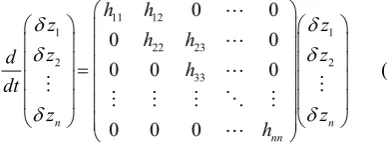
11 12
1 1
22 23
2 2
33
0 0
0 0
0 0 0
0 0 0
n n
nn
h h
z z
h h
z z
d h
dt
z z
h
δ δ
δ δ
δ δ
=
(12)
This is in the hierarchical contraction form that pro-vides the global feedback system with exponential stabil-ity.
In addition, the hierarchical contraction form provides exponential convergence for each individual state, zi
where i=1,2, , n. This is because the virtual dynamics for each state is
, 1 1
i ii i i i i
z h z h z
δ = δ + +δ + (13) where the second term can be regarded as a bounded disturbance term that diminishes to zero. In particular, the controlled variable, z1, converges to the reference
value exponentially which can be used for fast conver-gence control of a particular variable.
3. UAV Flight Path Control
3.1. Dynamical Model
[image:3.595.80.274.88.159.2] [image:3.595.115.236.460.514.2]This section provides a description of the contrac-tion-based backstepping controller synthesis with a sim-plified UAV model for flight path angle control.
Figure 1 shows the forces acting on the longitudinal axis of the UAV, the dynamical model is given by equa-tion (14) [16].
(
)
1 L Tsin gcos
mV V
q q M u
γ α γ
θ
= + −
=
= =
(14)
where γ is the flight path angle, θ is the pitch angle, q is the pitch rate, m is the aircraft mass, V is the air speed, T
is the thrust, α is the angle of attack, g is the gravitational acceleration, L is the aerodynamic lift and M is the aero-dynamic pitch moment which is defined as the control input u.
The lift force, L, is expressed in the following form.
( )
2
1
2 L
L= ρV SC α (15)
Figure 1. UAV dynamical model.
where ρ is the air density, S is the wing area and CL is the
lift coefficient and is a function of α.
The following assumptions were made to simplify the model and the control formulation.
• The control surfaces only produce aerodynamic moments. The aerodynamic forces produced were as-sumed to be small and neglected.
• The speed of the aircraft was maintained at a con-stant value independently.
• The control actuator dynamics were sufficiently fast, thus neglected.
Therefore, equation (14) was reduced to the form shown in equation (16).
( )
, gcosf t
V q
q u
γ α γ
θ
= −
= =
(16)
where f
( )
,t 1(
L( ) ( )
T t sin)
mV
α = α + α .
Equation (16) is a simplified dynamical model for the purpose of key concept demonstration and forms the ba-sis for the control formulation which will be presented in the next section.
3.2. Flight Path Angle Tracking
[image:3.595.88.289.612.721.2]The above control algorithm was applied to a flight path tracking problem of an UAV.
Figure 2 shows a block diagram of the closed-loop system, highlighting the subsystem nature of the algo-rithm.
Step 1:
Define the transformation * 1
z = −γ γ (17) where γ* is a reference flight path angle defined in
equa-tion (28). The z1-dynamics becomes
( )
(
*)
*1 , gcos 1
z f t z
V
α γ γ
= − + −
(18)
To define a suitable virtual control, we assume that
(
)
2 1
z = − −α Kz , where K>0, and consider the virtual dynamics of equation (18).
[image:3.595.307.534.625.706.2](
)
(
)
(
)
*
1 2 1 1 1
2 1 2
, sin
,
g
z Kf z Kz t z z
V f z Kz t z
δ γ δ
δ ′ = − − + + ′ + − (19)
For the subsystem in equation (19) to be in the con-traction region, the operation region is limited so that
1 min 1 g K K f V = +
′ whereK1>0 , then the subsystem given by equation (19) will be in the contraction region.
Step 2:
Hence the z2-dynamics becomes
2 1 1. z Kz q Kz α γ = + = − +
(20)
If we define z3 = −q q( )d where
( )
2 2 1
d
q = −K zδ + −γ Kz (21) and K2 >0, then the virtual dynamics will become
2 2 2 3
z K z z
δ = − δ +δ (22) which implies a contraction region.
Step 3:
Now, consider z3-dynamics
( )
3 d
z = −u q (23) If we let the control input u be
( )
3 3
d
u q= −K z (24) and K3 >0, then the virtual dynamics will become
3 3 3
z K z
δ = − δ (25) which implies a contraction region.
Hence the virtual dynamics for the entire system will be
1 11 12 1
2 2 2
3 3 3
0
0 1
0 0
z h h z
d z K z
dt z K z
δ δ δ δ δ δ = − − (26)
where
(
)
(
*)
11 2 1, gsin 1
h Kf z Kz t z
V γ
′
= − − + +
and h12= f z′
(
2−Kz t1,)
, is in the hierarchical contrac-tion form.Step 4:
For the tracked angle, γ(r), to be a particular solution so
that all trajectories contract onto it, the reference angle, γ*,
is defined as follows. Consider the resultant dynamics,
( )
(
*)
*1 1
2 2 2 3 3 3 3
, gcos
z f t z
V
z K z z
z K z
α γ γ
= − + − = − + = − (27)
It can be seen that z2=z3 =0 is a particular solution.
Putting the actual tracked flight path angle, γ(r), as a
par-ticular solution into the z1-dynamics,
( )
(
(
( ))
)
( ) ( )( )
(
(
( ))
)
( ) ( ) * * * * * cos 1r r r
r r
r r
g
f K
V
f f K
K
γ γ γ γ γ γ
α γ γ
γ α γ
− = − − − −
= − −
= +
(28)
where we had used the fact that
( )r f
( )
( )r gcos ( )rV
γ = α − γ , z2 =0
and the symbol t is omitted in equation (28) for neatness. Note that the difference between γ* and γ(r) is due to the
nonzero angle of attack, α, at equilibrium so a nonzero γ*
is required to account for this difference.
Hence the above formulated control law and reference flight path angle, γ*, tracks the flight path angle, γ(r).
4. Simulation Results
The synthesized control law was implemented and tested in Matlab for flight path angle stabilization and tracking problem.
To study the convergence of the implemented control-ler, an initial perturbation (away from equilibrium) was applied to the system and the system closed-loop re-sponse was examined.
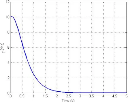
4.1. Flight Path Angle Regulation
The flight path angle regulation problem is the stabiliza-tion of the flight path angle to a reference value. It dem-onstrated the ability for the controller to reject perturba-tion exponentially fast. Figure 2 to 5 are obtained from the flight path stabilization simulation.
[image:4.595.313.537.531.708.2]Figure 4. Pitch angle response for stabilization the problem.
Figure 5. Control input for the stabilization problem.
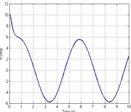
4.2. Flight Path Tracking
In the flight path tracking problem, the ability for the controller to track time-varying reference flight path an-gle was demonstrated. A sinusoidal reference was chosen as an example of time-varying signal. Figure 6 to 9
shows the results for the flight path angle tracking simu-lation.
In both examples, it was shown that exponential sta-bility was achieved by the control algorithm. This is due to the presence of a contraction region.
Furthermore, the controlled variable was made to be exponentially stable subjected to bounded disturbances due to the errors in virtual controls.
[image:5.595.62.287.302.481.2]Although simplified, this example demonstrated the potential of the contraction-based backstepping technique as an alternative to the Lyapunov backstepping technique in the formulation of a control algorithm that achieves exponential stability in a system.
Figure 6. Flight path angle error for the stabilization prob-lem.
Figure 7. Flight path angle for the tracking problem.
[image:5.595.312.538.313.496.2] [image:5.595.314.535.527.715.2]Figure 9. Control input for the tracking problem.
Figure 10. Flight path angle error for the tracking problem.
5. Conclusions
In this paper, a contraction-based backstepping technique using the hierarchical contraction structure was demon-strated. The unique hierarchical contraction structure with backstepping control formulation provides recursive control law that was formulated systematically. Expo-nential stability of the closed-loop system and individual controlled variable was achieved. The control algorithm was demonstrated on a flight path angle stabilization and tracking problem.
6. Acknowledgements
The authors would like to thank Nanyang Technological University and DSO National Laboratories for their sup-port on this project.
REFERENCES
[1] R. H. Stone, “The T-wing Tail-Sitter Unmanned Air
Ve-hicle: From Design Concept to Research Flight Vehicle,”
Proceedings of the Institution of Mechanical Engineers,
Part G: Journal of Aerospace Engineering, Vol. 218, No. 6, 2004, pp. 417-433 [2] J. Carl G. Schaefer and L. J. Baskett, “GoldenEye: The
Clandestine UAV,” in 2nd AIAA “Unmanned Unlimited”
Systems, Technologies, and Operations, 2003, pp. 1-11. [3] J. Escareno, R. H. Stone, A. Sanchez and R. Lozano,
“Modeling and Control Strategy for the Transition of a Convertible Tail-sitter UAV,” in European Control Con-ference, 2007.
[4] O. Harkegard, “Flight Control Design Using Backstep-ping,” Linkoping University, 2003.
[5] N. B. Knoebel and T. W. McLain, “Adaptive Quaternion Control of A Miniature Tailsitter UAV,” in 2008 Ameri-can Control Conference, 2008, pp. 2340-2345.
[6] A. A. Mian, M. I. Ahmad and D. Wang, “Backstepping based Nonlinear Flight Control Strategy for 6 DOF Aerial Robot,” in 2008 International Conference on Smart Man-ufacturing Application, 2008, pp. 146-151.
[7] F. M. Subolic, “Agile Flight Control Techniques for a Fixed-Wing Aircraft,” Massachusetts Institute of Tech-nology, 2009.
[8] J. H. Yang and W. C. Hsu, “Adaptive Backstepping Con-trol for Electrically Driven Unmanned Helicopter,” Con-trol Engineering Practice, Vol. 17, No. 8, 2009, pp. 903-913
[9] W. S. Lohmiller, “Contraction Analysis of Nonlinear Systems,” Massachusetts Institute of Technology, 1999. [10] W. Lohmiller and J. J. E. Slotine, “On Contraction
Anal-ysis for Non-linear Systems,” Automatica, Vol. 34, No. 6, 1998, pp. 683-696.
[11] W. Lohmiller and J. J. E. Slotine, “Control System De-sign for Mechanical Systems Using Contraction Theory,”
IEEE Transactions on Automatic Control, Vol. 45, No. 5, 2000, pp. 984-989
[12] J. Jouffroy and J. J. E. Slotine, “Methodological Remarks on Contraction Theory,” 2004 43rd IEEE Conference on Decision and Control (CDC) (IEEE Cat. No.04CH37601), Vol. 3, 2004, pp. 2537-2543.
[13] J. Jouffryo, “Integrator Backstepping Using Contraction Theory: A Brief Methodological Note,” 2002, p. 238. [14] B. B. Sharma and I. N. Kar, “Contraction Theory-based
Recursive Design of Stabilising Controller for A Class of Non-linear Systems,” IET Control Theory & Applications, Vol. 4, No. 6, 2010, p. 1005.
[15] M. Zamani and P. Tabuada, “Towards Backstepping De-sign for Incremental Stability,” 49th IEEE Conference on Decision and Control (CDC), 2010, pp. 2426-2431
[image:6.595.62.284.291.466.2]