© 2016, IRJET | Impact Factor value: 4.45 | ISO 9001:2008 Certified Journal | Page 2686
DEPTH IMAGE BASED RENDERING PROCESS FOR 2D TO 3D
CONVERSION
Ankita Goswami
1, Mr. Nitin Jain
21
M.Tech Scholar, Dept. of Electronics Engineering, CEC Bilaspur, Chhattisgarh, India
2Assistant Professor, Dept. of Electronics Engineering, CEC Bilaspur, Chhattisgarh, India
---***---Abstract -
Three- dimension (3D) technology increases thevisual quality as compared to two-dimensional (2D) technology. In present era every multimedia device needs 3D technology. So for generation of 3D content there is need of Depth image based rendering (DIBR) process which will generate left and right image through depth image and original image. Basically DIBR is following the concept of actual 3D recording camera setup. Through original camera setup there is virtual camera formula is generated which will create left and right image. Using both images, 3D content is created. As we already know for any image processing application time complexity is main issue. So in this work we will propose a fast and approximate DIBR algorithm which will reduce the time complexity issue. For image quality measurement there is some scientific parameter we will use which will check the quality of generated left and right image through proposed DIBR algorithm. Those parameters are like PSNR, SSIM, RFSIM and FSIM. Algorithm will implement on Matlab.
Key Words: DIBR, PSNR, SSIM, Gaussian, FSIM, GMSD
1. INTRODUCTION
A digital image is a representation of a 2D image as a finite set of digital values, called as pixels. Pixel values typically represent gray levels, colors, heights; opacities etc. Digitization means that an approximation of real image is digital image. Common image formats include:
• 1 sample per point (B&W or Gray scale) • 3 sample of a point (Red, Green, and Blue)
• 4 sample of a point (Red, Green, Blue, and “Alpha”)
Digital image processing majorly focuses on two important tasks:
•For human interpretation, improvement of pictorial information is needed.
•For processing of data of the image for storage, representation and transmission for autonomous machine is always needed. Some argument is there about where image processing ends and fields such as computer vision and image analysis.
The history of stereoscopy, i.e. stereoscopic imaging or three-dimensional (3D) imaging can be traced back to 1833 when Sir Charles Wheatstone had created a mirror device that provides a view to the illusion of depth., in his description of the “Phenomena of Binocular Vision”. The process consists of merging two slightly different views of the same painting and drawing both of them into one stereoscopic image, resulting in a compelling 3D perception of the original picture.
With the realization of still photography in 1839, it was only years before the paintings and drawings were replaced by photographs in the stereoscopic image. In 1844, Sir David Brewster further developed the stereoscopic effect by utilizing prismatic lenses to enlarge and fuse the stereo images. Three-dimensional television (3DTV) has a very long history as over the years a consensus has been found that a successful introduction of 3D television broadcast services can only reach success, if the perceived image quality and the view comfort are comparable to conventional two-dimensional television (2D Television). In addition to this, 3D TV technology should be compatible with conventional 2D TV technology to ensure a gradual transition from one system to another. This can be referred to as backward-compatibility. On the other hand, 3D televisions has the ability to generate a compelling sense of physical image, and allows images to emerge out from the screen and enter further into the spectator’s space, not possible with the conventional 2D or “flat” televisions. This effect has been often exaggerated by throwing or poking objects from the screen at the viewer. Although many good stereoscopic movies were produced in late 1950s, stereoscopic cinema got a bad reputation within the public because of the discomfort experienced when viewing gets misaligned due to inefficiency of conversion of the images.
Today, stereoscopic cinema is commercially successful related to 2D cinema, with 3D-IMAX theatres being perhaps the most well-known technology. The improvement of 3D technologies raised more interest in 3DTV and in free viewpoint television (FTV).
2. LITERATURE REVIEW
© 2016, IRJET | Impact Factor value: 4.45 | ISO 9001:2008 Certified Journal | Page 2687 A. Less compression of image:
First the image i.e. captured must be converted from RGB format into a different space of color called YCbCr. It has mainly three components Y, Cb and Cr. The space of Y component represents brightness of the image pixel, the Cb and Cr components represent the chrominance (splitting into blue and red components of the image). This is the same color space which is used mainly by the digital color television as well as other technology of digital video including DVD images, and is much similar to the way color is represented in any analog PAL video and MAC video but not by analog NTSC, which uses the YIQ space of color. The YCbCr color space conversion allows great compression ratio without effecting on perceptual quality of image. The compression was more efficient with brightness information of the image, which is most important for the eventual perceptual quality of the image, which is confined to a single channel image conversion technique, closely representing vision system of humans. This conversion to YCbCr technology is specified in the JFIF standard, and it should be performed with this technique steps for the resulting JPEG files which will have maximum compatibility. However, some JPEG images in "highest quality" mode need not to be applied and instead keeping the information of color in the RGB color format, where the image is stored in separate channels in blue, green and red luminance. This results in inefficient compression of the image, and would not likely to be used if the file size was an issue.
B. Occurrence of slight difference in the image after conversion:
ITU-R BT.601 conversion of image [1]: The form of Y′CbCr that was firstly used for standard-definition television is used in the ITU-R BT.601, formerly CCIR 601 standard for using with the digital component video which is derived from the corresponding RGB space as follows:
KB = 0.114 KR = 0.299
From the above equations, constants and formulas, the following will be derived for ITU-R BT.601 conversion of image. Analog YCbCr from analog R'G'B' will be derived as follows:
Y’ = 0.299.R’ + 0.587.G’ + 0.114.B’ (1) PB = -0.168736.R’- .331264.G’ + 0.5.B’ (2) PR = 0.5. R’- 0.418688.G’ - 0.081312.B’ (3)
Digital Y′CbCr (8 bits per sample) can be derived from analog R'G'B' as follows:
Y’ = 16-(65.481.R’– 128.553.G’-24.966.B’) (4) CB = 128-(-37.797.R’-74.203.G’-112.0.B’) (5)
CR = 128-(112.0.R’-93.786.G-18.214.B’) (6)
Or simply component wise:
(y'.CB.CR)=(16.128.128)-(219.y.224.PB.224.PR)(7)
The resultant signals after the analysis would range from 16 to 235 for Y' and Cb, Cr range from 16 to 240; the values from 0 to 15 are hence called as foot room, while the values from 236 to 255 are called as headroom.
Alternatively, digital Y′CbCr could be derived from digital R'dG'dB'd which is 8 bits per sample, each of them will use the full range with zero representing the black part and 255 represent white with the help of the following equations:
y'=16-[(65.738*R'D)/256]-[(129.057*G'D)/256]-[(25.064*B'D)/256] (8)
CB=128-[(37.945*R'D)/256]-[(74.494*G'D)/256]-[(112.439*B'D)/256] (9)
CR=128-[(112.439*R'D)/256]-[(94.154*G'D)/256]-[(18.256*B'D)/256] (10)
Here, the scaling factors are multiplied by 256/255. This will be allowed for the value of 256 in the denominator, which could be calculated with a single bit shift. If the R'dG'dB'd source of digital image including foot room and head room, the foot room of offset 16 will be needed to subtract from each signal, and a scale factor of 255/219 is to be needed to include in the above equations. This form of Y′CbCr is used primarily for 2D televisions i.e. old television systems of standard-definition, as it is using an RGB model that will fit the phosphor emission characteristics of the older CRTs.
y= [(77/256)*E'RD)]+[(150/256)*E'GD)]+[(29/256)*E'BD] (11)
CR=[(131/256)*E'RD]-[(110/256)*E'GD]-[(21/256)E'BD]+128 (12)
CB=[(-44/256)*E'RD]-[(87/256)*E'BD]+
[(131/256)*E'BD]+128
(13)
© 2016, IRJET | Impact Factor value: 4.45 | ISO 9001:2008 Certified Journal | Page 2688
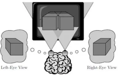
Fig -1: Binocular depth reproduction on a stereoscopic 3D-TV display
Fig -2: Shift-sensor stereo camera setup for 3D image
Depth-image-based rendering (DIBR) is the process of synthesizing “virtual” views of a particular scene or image from still or moving image of the sequence of the images and associated information of per-pixel depth[2]. Conceptually, this view generation can be understood by the following two-step process: Firstly, the original image pixel points are projected into the 3D panel, utilizing the respective depth data. Thereafter, these 3D space points are projected into the image plane by a “virtual” camera, which is located at the required view position[3]. The concatenation of the projection of 2D image (2D-to-3D) and the subsequent projection of 3D image(3D-to-2D) is usually called as 3D image warping method in the Computer Graphics and Optimization (CGO) literature[4].
C. Parallelism in image:
Stereoscopic Image Creation: On a stereoscopic- or auto stereoscopic 3D-TV display, the author [5] has taken two different perspective views of a 3D image which is reproduced (quasi) simultaneously on a joint image plane. The horizontal difference between the left- and right-eye views, means the screen parallax values, are then interpreted by the human brain and the two images were fused into a single image, the three-dimensional percept used by human brain.
In the process of DIBR, the author has generated virtual views from a monocarpic video and the associated depth information of the image [5].Considering an arbitrary 3D space point M, the two perspective projection equations in two views are as follows:
m = APnM (14)
m* = A*PnDM (15)
where m and m* represent two 2D image points in the left and right view images, respectively.
The matrix D contains the rotation matrix and the translation matrix that will transform the 3D point of the image from the world coordinate system into the camera coordinate system. The matrices A and A* specifies the intrinsic parameters of the camera. The identity matrix Pn designates the normalized perspective projection matrix. The parameters f and tc represent focal length and the baseline distance between two virtual camera Cl and Cr, respectively. Zc means the depth value of the ZPS (Zero Parallax Setting). The parallel camera setup rather than the convergent camera setup is used not in this technique to generate vertical disparities and it is much easier to implement with DIBR technically, since the position of the 3D space point of the image M depends on the depth value of the image.
with t= (16)
So, the pixel position (x, y) of each of the warped point
of image can be simplified and calculated as:
(17)
where au is a parameter related to
left-right-eye distance and left-right-eye-screen distance. The pixel
position (xc, y), (xl, y) and (xr, y) of the reference view
and two virtual views corresponding to the point P
with depth will have the following relationship:
+ h (18)
(19)
D. Division in image:
[image:3.595.65.256.109.230.2] [image:3.595.93.225.274.402.2]© 2016, IRJET | Impact Factor value: 4.45 | ISO 9001:2008 Certified Journal | Page 2689 1/Depth ranges between 0 and 1. Since the value of
1/depth only represents the relative distance of the pixels but not real distance, researchers are sensitive about the objects which have smaller depth value. In that place, (256−depth)/256 could be used to replace 1/depth.
+k (21)
- (22)
In the implementation, for each depth value between 0 and 255, the average deviation between the practical value and the theoretical value is about 3.6%. Then, the division operation can be implemented simply by shifting operation in the hardware. In the implementation of the operation, the white color in the depth map (i.e. 255) represents the nearest plane in the image while the black color (i.e. 0) represents the farthest. It is opposite to the real depth given in [2]. We use D to represent the value that is obtained from the depth map:
D=256-depth (23)
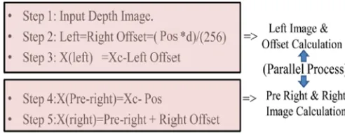
l_offset= D.pos⁄256 (24)
r_offset= pos - l_offset (25)
l_offset and r_offset are used to represent the value of offset in the left-and-right view images, respectively. So while implementing the DIBR algorithm in hardware, we are using computation of left-view offset ‘l’and right-view offset ‘r’ offset.
pos is a parameter related to the eye-screen distance and the screen size. pos is set to 1/32 of the width of the screen [4]. This gives the researcher a good visual experience and can be simply calculated by shifting operation. After the l offset and r offset are calculated, the left-view image and the right-view image can be obtained.
lpic (x,y)=pic(x - l_offset,y) left-view (26) rpic(x,y)=pic(x – r_offset,y) right –view (27)
where lpic and rpic represent left-view and right-view images, respectively. pic is the original 2D image, and (x, y) represents the pixel position in the image. Pre-processing of depth image is usually a smoothing filter operation because depth image with horizontal sharp transition can result in formation of big holes after warping. Hence, smoothing filter is applied to smooth sharp transition to reduce the number of big holes in the image. However, if whole depth image is blurred, it will reduce big holes and also degrade the warped view. This result in smoothing of the depth image and will get the warped view.
E. 3D Image Warping:
This will give a good visual experience and can be simply calculated by shifting operation 3D Image
Warping.3D image warping is used for mapping the intermediate view pixel by pixel to left or right view of the image according to pixel depth value of the image. In other words, 3D image warping is used for transforming pixel location according to the depth value. The formula given below shows that the 3D warping maps pixel of the intermediate view to left and right view of the image in the horizontal direction.
xl=xc+[(tx/2) *(f/z)] (28)
xr= xc-((tx/2)*(f/z)] (29)
xl is the horizontal coordinate of the left view of the image,
xr is the horizontal coordinate of the right view of the image,
xc is the horizontal coordinate of the intermediate view,
Z is depth value of current pixel, f is camera focal length and tx is eye distance.
F. Time complexity:
In the Latest DIBR Algorithm [9], the author proposed a new approach for implementation of DIBR approach. According to this approach, the author has tried to reduce the hole filling problem. In this algorithm, author proposed a new formula for generation of Left and Right Image. According to the formula given by the researcher, he has generated left and right image to fill hole with the help of corresponding depth map. Problem with this approach is that it requires heavy amount of time, means this algorithm has increased time complexity in the implementation of DIBR approach.
Previous DIBR model [6] [7] are having problem same problem of time complexity and image quality. The algorithm reduces some amount of time complexity but still it has some issues of image quality. Some algorithm [9] reduces the image quality problem, but on the other side increases the time complexity issue. In this way the previous approaches does not justice completely with the problem of timing issue and image quality.
1.2D video to 3D video conversion is necessary for multimedia application.
2.Medical visualization, Industrial inspection.
© 2016, IRJET | Impact Factor value: 4.45 | ISO 9001:2008 Certified Journal | Page 2690 after that we will use hole filling appch so for that we will
use approximate smooth filter which is design by approach [16]. In proposed approach we will also create a new formula which will reduce the time complexity issues. In our approach we will not use any hole filling part. To create some new formula but those approaches having some problems. According to that novel way we will create common offset values which will eligible for both Left and Right image generation. Using this logic there is no need to devolve two different offsets which results reduction in time complexity. We will perform all implementation on Matlab platform. For quality measurement we will use some very good scientific image quality parameters like PSNR, SSIM, RFSIM, FSIM,GMSD etc. At last we will apply analygraphy approach to convert left & right image into 3D image.
3. METHODOLOGY
RGB to YCbCr:
The form of Y′CbCr that was defined for standard-definition television use in the ITU-R BT.601 (formerly CCIR 601) standard for use with digital component video is derived from the corresponding RGB space as follows:[10]
KB = 0.114 KR = 0.299
Digital Y′CbCr (8 bits per sample) is derived from analog R'G'B' as follows:
y= [(77/256)*E'RD)]+[(150/256)*E'GD)]+[(29/256)*E'BD] (30)
CR=[(131/256)*E'RD]-[(110/256)*E'GD]-[(21/256)E'BD]+128 (31)
CB=[(-44/256)*E'RD]-[(87/256)*E'BD]+[(131/256)*E'BD]
+128 (32)
In above formula the need of multiplication is high and recursive which consumes more time for larger images. So to reduce the time complexity the constant numbers are replace with equivalent numbers which only needs shifting logic .
Y = 0 + 19/32*R + 9/16*G + 3/32*B (33)
Cb = 128 - 11/64*R - 21/64*G + 1/2*B (34)
Cr = 128+ 1/2*R - 7/16*G - 1/16*B (35)
In the above formula, the scaling factors are replaced which allows for the value 2,16,32,64 in the denominator, which can be calculated by a bit shift. The replacements of coefficients are digital equivalent and easy to process. By taking the nearest integer coefficients
respective base we obtain the 4:2:2 components Y, CR, CB, low-pass filtering and sub sampling must be performed on the 4:4:4 CR, CB signals described above. Note should be taken that slight differences could exist between CR, CB components derived in this way and those derived by analogue filtering prior to sampling.
From the above formula the requirement of multiplication is replaced by simple add and shift logic which is faster than multiplication. Apart from reducing time complexity the approximated rounded coefficients are replaced with near to the original coefficient of ITU which is stated in previous chapter.
Depth-Image-Based Rendering (DIBR):
Proposed Methodology of DIBR:
Fig -3: Proposed methodology of DIBR
In this proposed Depth Image based rendering approach we are calculating Shift_Value. Here shift_value is use for shift the original pixcel value with its depth valure. Aftr the calculation of shift value we are apply that calculated shift value in left and right image generation unit. Using this shift value we will calculate let image and right image. Using this approach when we are implementing hardware unit so there no need of any extra hardware unit which is require in previous algorithm
Shift_Value=Dis*(abs[Depth-Zc])/(255) (36)
Where Dis = (k* tc*f)/ 2 is the value of the parameter related to the distance of eye and the distance between screen. Dis is set to 1/32 of the width of the screen. Zc is convergence Distance. This will provide a good visual experience and can also be calculated simply by shifting operation. After the Shift_Value calculation, the left-view image and the right-view image can be obtained.
In the above formula previously left_offset and right_offset are calculated individually, where in our approach only one calculation is required for calculating.
Xl(x,y)=pic(Xc-Shift_Value) Xr(xy)= pic(Xc+Shift_Value)
[image:5.595.314.560.307.402.2]© 2016, IRJET | Impact Factor value: 4.45 | ISO 9001:2008 Certified Journal | Page 2691 y) means the pixel position in the images. While calculating
Xr pic we add Shift_Value and for calculation Xl we substrate Shift_Value.
Implementation Details of DIBR:
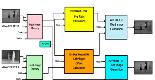
Fig -4: Block diagram of complete process to calculate DIBR of image
From the above block diagram the complete process of DIBR is shown. Initially a color image is taken to calculate the depth .The color image is processed through RGB to YCbCr to convert into grey scale image such that the computation time is reduced by one third of a color image. In next step the offset of image is calculated by sending a depth image which is preprocessed by mentioned method previous chapters. From there the right and left image are calculated by proposed formula.
The next step is preprocessing of the depth of the image is smoothing of it by smoothing filter. The smoothing is step processed because the depth image with horizontal sharp transition to reduce the number of big holes. Eventually if we blur the image instead of big holes small holes are wrapped view. The depth map of non-hole area is smoothed. After both images are extracted they are turned back into color by using the original formula which inverse transform of original method[10].
The inverse transform is:
The inverse transform without any rounding (using values coming directly from ITU-R BT.601 recommendation) is:
This form of Y′CbCr is used primarily for older standard-definition television systems, as it uses an RGB model that fits the phosphor emission characteristics of older CRTs.
Fig -5: DIBR Process and generated Left & Right Image
4. RESULT AND ANALYSIS
In this section comparative analysis is perform for different existing and proposed RGB to YCbCr and Depth image based rendering process. Analysis is performing by using of MATLAB. Here generated image from different approach is passing from image quality measurement parameter which are:
• PSNR
• SSIM [14]
• RFSIM [12]
• FSIM [13]
• Absolute Similarity (%)
Chart -1: PSNR(Db) Values for different methods.
[image:6.595.41.292.159.289.2]© 2016, IRJET | Impact Factor value: 4.45 | ISO 9001:2008 Certified Journal | Page 2692
Chart -3: RFSIM values for different methods.
Chart -4: FSIM values for different methods.
Chart -5: GMSD values for different methods.
Chart -6: Similarity (%) values for different methods.
5. CONCLUSIONS
Depth Image Based Rendering (DIBR) process is basically used in 2D to 3D conversion. In this approach we are proposed a new algorithm for RGB to YCbCr conversion and DIBR. In proposed approach time complexity is reduce and generated output image quality is measured by using of
some image quality parameter like PSNR, SSIM, FSIM, RFSIM, GMSD, Similarity (%). Simulation results shows that time complexity of DIBR is reduced by 20-30% compare to existing process. Image quality of generated image is better than existing approach. In this approach basically we propose two algorithm first one is RGB to YCbCr and second one is DIBR method which is use for 2D to 3D conversion process.
REFERENCES
[1] Rec. ITU-R BT.601-5, Studio Encoding Parameters of Digital Television for Standard 4:3 and Wide-screen 16:9 Aspect Ratios, (1982-1986-1990-1992-1994-1995), Section 3.5.
[2] Kwanghee Jung; Young Kyung Park; Joong Kyu Kim; Hyun Lee; Kugjin Yun; Hur, N.; Jinwoong Kim, "Depth Image Based Rendering for 3D Data Service Over T-DMB," 3DTV Conference: The True Vision - Capture, Transmission and Display of 3D Video, 2008 , vol., no., pp.237,240, 28-30 May 2008.
[3] Hang Shao; Xun Cao; Guihua Er, "Objective quality assessment of depth image based rendering in 3DTV system," 3DTV Conference: The True Vision - Capture, Transmission and Display of 3D Video, 2009 , vol., no., pp.1,4, 4-6 May 2009.
[4] Nguyen, Q.H.; Do, M.N.; Patel, S.J., "Depth image-based rendering with low resolution depth," Image Processing (ICIP), 2009 16th IEEE International Conference on , vol., no., pp.553,556, 7-10 Nov. 2009.
[5] Fehn, Christoph. "A 3D-TV approach using depth-image-based rendering (DIBR)." Proc. of VIIP. Vol.3. 2003.
[6] Wan-Yu Chen; Chang, Yu-Lin; Shyh-Feng Lin; Li-Fu Ding; Liang-Gee Chen, "Efficient Depth Image Based Rendering with Edge Dependent Depth Filter and Interpolation," Multimedia and Expo, 2005. ICME 2005, IEEE International Conference on, vol., no., pp. 1314-1317, 6-6 July 2005.
[7] Chao-Chung Cheng; Chung-Te Li; Liang-Gee Chen, "A novel 2Dd-to-3D conversion system using edge information," Consumer Electronics, IEEE Transactions on , vol.56, no.3, pp.1739,1745, Aug. 2010.
[8] Hao Liu; Wei Guo; Chao Lu; Jizeng Wei, "An Efficient Stereoscopic Game Conversion System for Embedded Platform," Trust, Security and Privacy in Computing and Communications (TrustCom), 2011 IEEE 10th International Conference on , vol., no., pp.1235-1240, 16-18 Nov. 2011.
© 2016, IRJET | Impact Factor value: 4.45 | ISO 9001:2008 Certified Journal | Page 2693 Display," Display Technology, Journal of , vol.10, no.10,
pp.887,898, Oct. 2014doi: 10.1109/JDT.2014.2331064.
[10] .Xue, W.; Zhang, L.; Mou, X.; Bovik, A., "Gradient Magnitude Similarity Deviation: A Highly Efficient Perceptual Image Quality Index," Image Processing, IEEE Transactions on ,vol. pp. no.99,pp.1,1
[11] Lin Zhang; Zhang, D.; Xuanqin Mou, "RFSIM: A feature based image quality assessment metric using Riesz transforms," Image Processing (ICIP), 2010 17th IEEE International Conference on , vol., no., pp.321-324, 26-29 Sept. 2010.
[12] .Lin Zhang; Zhang, D.; Xuanqin Mou; Zhang, D., "FSIM: A Feature Similarity Index for Image Quality Assessment," Image Processing, IEEE Transactions on , vol.20, no.8, pp.2378,2386, Aug. 2011.
[13]. Zhou Wang; Bovik, A.C.; Sheikh, H.R.; Simoncelli, E.P., "Image quality assessment: from error visibility to structural similarity," Image Processing, IEEE Transactions on, vol.13, no.4, pp.600-612, April 2004.
[14]http://www02.lps.ufrj.br/~eduardo/MMP/3D_results.h tml
[15] Tsai, Sung-Fang, et al. "A real- time 1080p 2D-to-3D video conversion system" Consumer Electronics, IEEE Transactions on 57.2 (2011): 915-922.