© 2015, IRJET.NET- All Rights Reserved
Page 1482
Seismic Analysis of G+5 Framed Structures with and Without Floating
Columns Using ETABS-2013 Software
Umesh P. Patil
1, Shivanand S Hallur
21. Associate Professor, Dept. of Civil Engg, KLE Dr .MSSCET, Belagavi – 590008 (Karnataka). 2. M-Tech Student in Dept. of Civil Engg, KLE Dr. MSSCET, Belagavi – 590008(Karnataka).
………***………
ABSTRACT
In order to have more area for parking space and for other amities, concept of floating columns in multi-storey framed structure is becoming popular stability used structural integrity of such structures while resisting earthquake becomes critical. In the paper G+5 storey RCC structure in considered for earthquake analysis. For comparison of three models are used, one with normal structure, second with shear walls and third with masonry infill walls. All the three methods Equivalent static method, response spectrum and time history method were used for analysis ETABS-2013 Software was used and structure was assumed to be situated in earthquake Zone III on a medium soil(type II). The parameters evaluated were Base shear, Storey drift and Displacement. The multi-storey building with shear walls which had performed better than other models(normal building and multi-storey building with masonry infill walls) in resisting earthquake as per IS 1893:2002.
Key words:
Floating columns, Shear wall, Masonry
infill wall, Equivalent static method, Response
spectrum and Time history.
1.
INTRODUCTION
Floating Columns
A column is supposed to be a vertical member starting from foundation level and transferring the load to the ground. The term floating column is also a vertical element which ends at its termination level rests on a beam which is a horizontal member. The beams in turn transfer the load to other columns below it. Such columns where the load was considered as point load.
Fig 1: Floating Columns
The floating columns will be provided above the ground floor, there will be more space is available for parking purpose, auditorium purposes and assembly hall. The column is assumed pinned at the base and it will be acting as point load on the beams or girders and all loads will transfer to beam to foundation.
Shear Wall
© 2015, IRJET.NET- All Rights Reserved
Page 1483
Fig 2: RC Shear wallMasonry infill wall
The infill wall is the supported wall that closes the perimeter of the building constructed. The infill wall will be provided at inner and outer frames. It will bear its own weight, infill wall also acts as a non load bearing wall and also load bearing wall.
Fig 3: RC Effective width of masonry infill wall
The below formulas are used for the masonry infill wall width calculation.
Calculation of infill width:
W=0.175 ( d=
=
Where,
W= Width of masonry infill wall.
λ= Co-efficient to determined equivalent width of infill.
t= Thickness of masonry infill wall. h= Height of masonry infill wall. H= Height of RC frame.
l= Length of infill.
d= diagonal length of the masonry infill. Modulus of elasticity of masonry infill.
(
= Modulus of elasticity of concrete. )
= Moment of inertia of the column. = Moment of inertia of the beam.
2. MODELING AND BUILDING DATA
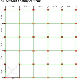
[image:2.612.323.575.355.611.2]2.1 Without floating columns
[image:2.612.38.290.398.566.2]© 2015, IRJET.NET- All Rights Reserved
Page 1484
Fig 5: Elevation of the building Without floatingcolumns.
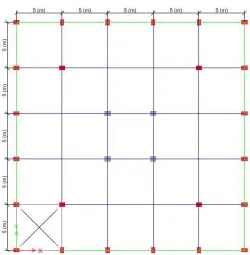
[image:3.612.315.575.65.299.2]2.2 With floating columns
Fig 6: Plan of the building with floating columns.
Fig 7: Elevation of the building With floating columns and shear walls.
Fig 8: Elevation of the building With floating columns and masonry infill walls.
[image:3.612.37.288.91.294.2] [image:3.612.332.578.346.569.2] [image:3.612.37.287.351.606.2]© 2015, IRJET.NET- All Rights Reserved
Page 1485
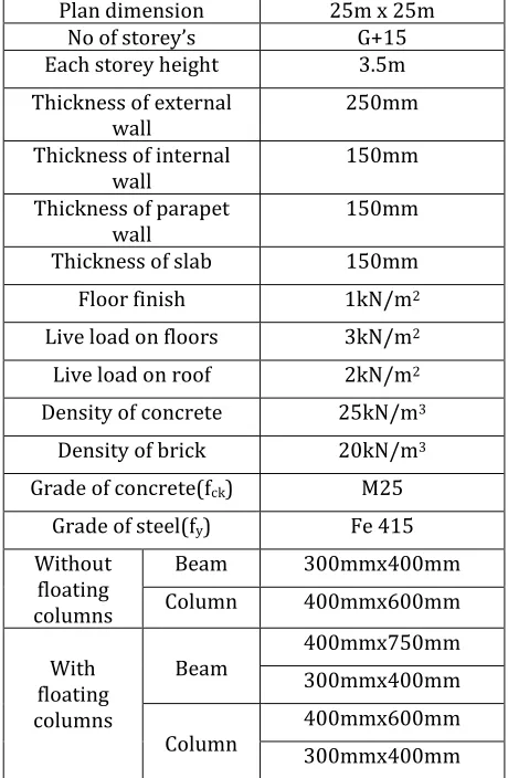
2.3 Building DataPlan dimension 25m x 25m
No of storey’s G+15
Each storey height 3.5m
Thickness of external wall
250mm
Thickness of internal wall
150mm
Thickness of parapet wall
150mm
Thickness of slab 150mm
Floor finish 1kN/m2
Live load on floors 3kN/m2
Live load on roof 2kN/m2
Density of concrete 25kN/m3
Density of brick 20kN/m3
Grade of concrete(fck) M25
Grade of steel(fy) Fe 415
Without floating columns
Beam 300mmx400mm
Column 400mmx600mm
[image:4.612.29.259.123.475.2]With floating columns Beam 400mmx750mm 300mmx400mm Column 400mmx600mm 300mmx400mm
Table 1: Building data and Dimensions
2.4 Analysis of Building
Equivalent static and response spectrum method and time history are used for the analysis of with and without floating columns having shear walls and masonry infill walls. In equivalent static analysis single mode of vibrations are considered. Base shear can be determined by multiplying total seismic weight of building to coefficient of acceleration spectrum value. In response spectrum method, dynamic characteristics are considered for analysis. In this method multiple modes of vibrations are considered where base shear of each mode can be calculated separately. It can be calculated by determining the modal mass and modal mass participation factor for each mode.
EQX- Equivalent static in X direction EQY- Equivalent static in Y direction RSX- Response spectrum in X direction
RSY- Response spectrum in Y direction THX-Time history in X direction THY- Time history in Y direction
3. RESULTS AND DISCUSSION 3.1(Without floating columns) 3.1.1Base shear
MODEL Normal multi-storey building multi-storey building with shear walls multi-storey building with masonry infill walls Base shear
in kN (EQ)
1456.818 1525.49 1479.844
Base shear in kN (RS)
1469.770 1525.490 1482.210
Base shear in kN (TH)
[image:4.612.317.585.187.533.2]5029.45 10012.55 7404.02
Table 2: Base shear
Chart 1:Baseshear without floating column
Compared to Equivalent static, response spectrum and time history methods, the base shear is reduced in equivalent static analysis at 60% and in response spectrum analysis at 60%.
3.1.2
Storey drift
(Without floating columns)© 2015, IRJET.NET- All Rights Reserved
Page 1486
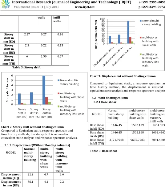
walls infillwalls
Storey drift in mm (EQ)
2.27 0.27 0.16
Storey drift in mm (RS)
2.5 0.22 0.15
Storey drift in mm (TH)
[image:5.612.32.568.49.656.2]6 1.50 0.57
Table 3: Storey drift
Chart 2:Storey drift without floating column
Compared to Equivalent static, response spectrum and time history methods, the storey drift is reduced in equivalent static analysis and response spectrum analysis.
3.1.3Displacement(Without floating columns)
MODEL
Normal multi-storey building
multi-storey building with shear walls
multi-storey building with masonry infill walls Displacement
in mm (EQ)
31.2 4.7 2.6
Displacement in mm (RS)
36.1 4.1 2.2
Displacement in mm (TH)
93 27 8.6
Table 4: Displacement
Chart 3:Displacement without floating column
Compared to Equivalent static, a response spectrum and time history method, the displacement is reduced in equivalent static analysis and response spectrum analysis.
3.2 With floating column 3.2.1 Base shear
MODEL
Normal multi-storey building
multi-storey building with shear walls
multi-storey building with masonry infill walls Base shear
in kN (EQ)
1446.45 1502.179 1454.583
Base shear in kN (RS)
1446.45 1502.168 1602.4362
Base shear in kN (TH)
3121.5948 9632.7283 7091.4605
© 2015, IRJET.NET- All Rights Reserved
Page 1487
Chart 4:Base shear
Compared to Equivalent static, a response spectrum and time history method, the base shear is reduced in equivalent static analysis and response spectrum analysis.
3.2.2 Story drift
MODEL
Normal multi-storey building
multi-storey building with shear walls
multi-storey building with masonry infill walls Story drift
in mm(EQ)
2.6 0.273 0.569
Story drift in mm(RS)
2.756 0.23 0.654
Story drift in mm(TH)
[image:6.612.36.295.83.282.2]6.97 1.473 2.28
Table 6: Story drift
Chart 5:Storey drift
Compared to Equivalent static, response spectrum and time history methods, the storey drift is reduced in equivalent static analysis and response spectrum analysis.
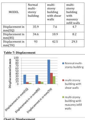
3.2.3 Displacement
MODEL
Normal multi-storey building
multi-storey building with shear walls
multi-storey building with masonry infill walls Displacement in
mm(EQ)
35.9 7.6 4.7
Displacement in mm(RS)
34.6 10.9 8.2
Displacement in mm(TH)
93 42.5 29.3
Table 7: Displacement
Chart 6:Displacement
Compared to Equivalent static, a response spectrum and time history method, the displacement is reduced in equivalent static analysis and response spectrum analysis.
4. CONCLUSION
Following are the broad conclusions in case of seismic analysis of RCC G+5 framed structure with floating columns.
Out of all the three methods used to evaluate base
[image:6.612.312.586.161.548.2]© 2015, IRJET.NET- All Rights Reserved
Page 1488
performed better compared to normalmulti-storey and masonry infill walls.
Out of all the three methods used to evaluate
storey drift, Multi-storey building with shear walls has performed exceedingly well when compared with normal multi-storey and masonry infill walls.
Out of all the three methods used to evaluate
displacement, Multi-storey building with masonry infill walls has performed exceedingly well when compared with normal multi-storey and shear walls.
Time history analysis presents peak value of base
shear for multi-storey building with shear walls.
Response spectrum analysis presents lowest
value of storey drift for multi-storey building with shear walls.
Equivalent static method of analysis presents
lowest value of displacement for multi-storey building with masonry infill walls.
All the values (Base shear, Storey drift and
displacement) are within the permissible limit except the displacement provided by Time history analysis for normal multi-storey building(being more than 84mm).
Thus for multi-storey building with shear walls
pre within the permissible limit except the storey drift has relatively performed normal multi-storey building and masonry infill walls in overall assessment.
ACKNOWLEDGEMENT
The authors would like to thank Shri S C Metagud Chairman Governing council and Dr. M. S. Sheshgiri college of Engineering and Technology, Belgavi for their kind support and providing good infrastructure. The authors are also grateful to Prof. (Smt) Bharti Chnivalar Head of Department for her encouragement and support.
REFERENCES
[1] Arlekar Jaswant N, Jain Sudhir K. and Murty C.V.R, (1997), “Seismic Response of RC Frame Buildings with Soft First Storeys”. Proceedings of the CBRI Golden Jubilee Conference on Natural Hazards in Urban Habitat, 1997, New Delhi.
[2] Fall H.G (2006), “Direct Stiffness Method For 2D Frames-Theory of structure”.
[3] Bardakis V.G., Dritsos S.E. (2007), “Evaluating assumptions for seismic assessment of existing buildings “.Soil Dynamics and Earthquake Engineering 27 (2007) 223–233.
[4] Mortezaei A., Ronagh H.R., Kheyroddin A., (2009), “Seismic evaluation of FRP strengthened RC buildings subjected to near-fault ground motions having fling step”. Composite Structures 92 (2010) 1200–1211.
[5] K. N. V. Prasada Rao, K. Seetharamulu, and S. Krishnamoorthy, “Frames with staggered panels: experimental study”, Journal of Structural Engineering, VOL 110, No. 5, Page no: 1134-1148, 1984.
[6] Hartley Gilbert and Abdel-Akher Ahmed, “Analysis of building frames” Journal of Structural Engineering, Vol.119, No. 2, Page no: 468-483, 1993.
[7] Prerna NautiyalA*, Saleem AkhtarA and Geeta BathamA” Seismic Response Evaluation of RC frame building with Floating Column considering different Soil Conditions” International Journal of Current Engineering and Technology, Vol.4, No.1,2014.
[8] IS 1893(Part 1): 2002”Criteria for Earthquake Resistant Design Of Structures Part 1 General Provisions and Buildings (Fifth Revision) Bureau of Indian Standards New Delhi.
[9] Dr. Vinod Hosur “Earth Quake Resistant Design of Building Structures” Wiley India Pvt. Ltd. Publications, first edition 2013
[10] Agarwal Pankaj, Shrikhande Manish (2009), “Earthquake resistant design of structures”, PHI learning private limited, New Delhi.
© 2015, IRJET.NET- All Rights Reserved
Page 1489
BIOGRAPHIES
Shri Umesh P. Patil is working as a Associate Professor, Civil Engineering Department in KLE Dr. M. S. Sheshgiri College of Engineering and Technology, Belagavi,590 008 Karnataka. He has work experience of 20 years. He has published 10 papers in international journals and presented 3 papers in international conferences. He has written a text book entitled as “Oil Power Hydraulics and Pneumatics” (1994)