© 2015, IRJET.NET- All Rights Reserved
Page 1365
DESIGN FEASIBILITY AND STRUCTURAL INTEGRITY OF PAN DOWN
COMPOSITE STRUCTURE
Deepak Srivastava, N.K Kelageri, Rajesh Deshilinge Gowda
1
Dept of Mechanical Engineering, KLE Dr. M.S Sheshgiri College of Engg & Tech, Belagavi, Karnataka, India
2Dept of Mechanical Engineering, KLE Dr. M.S Sheshgiri College of Engg & Tech, Belagavi, Karnataka, India
3
Director at Copes Tech PVT LTD. Bangalore, Karnataka, India
---***---Abstract - Study of the design the feasibility and
structural analysis of stuffed hat pandown sandwich composite panel of pan down stuffed hat stiffened panel to optimize for weight further from the existing stepped sandwich core model. These designs have more benefits compare to conventional stiffened panel made of Aluminium. The proposed design leads to minimization of fasteners, secondary bonding and assembly operation due to single piece stiffened panel construction, hence lesser weight, cost, fuel consumption etc.
Today aircraft structures made of sandwich composites consist of constant core between the two face sheets which has very high strength/wt, stiffness/wt, and most commonly used in aircraft structure due to less weight. There is still an opportunity to save the weight by providing it as a pan down approach (stuffed hat model). Study is been done for the main landing gear door panel of A320 and carried out feasibility for MLGD. The project outcomes show that stuffed hat model shows better results as compared to full sandwiched core model, it means still there are chances to save the weight for any panel of aircraft and if that can be done for max number of panels in the aircraft, one will be able to save much of weight in the aircraft so that we can provide number of advantages.
Key Words:
MLGD, Laminates, Stress, F.I, Buckling
Factor.
1. INTRODUCTION
The aircraft has the following fuselage doors like Passenger door, main gear door panel, nose gear door panel, cargo door, fuselage door etc. so if we able to save some kg’s of wait for one door panel and if apply the same for all the panels of aircraft, it means we will be able to save a lot of weight which always used to be the major issue for any aircraft. We are carrying out the feasibility and structural integrity of main landing geardoor panel. As we know composite materials has got many benefits as compared to metals in terms of weight,
stiffness, strength etc. and here minimizing fasteners, secondary bonding and assembling operation by doing it as a single piece carbon fiber composite means we are avoiding the complexity to model the panel.
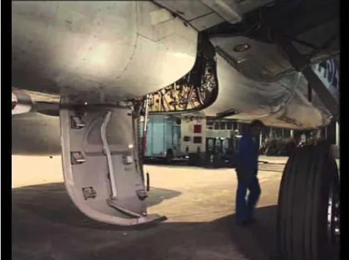
[image:1.595.308.559.379.566.2]Structures made of sandwich composites consist of two face sheets and a core between the two skins which has very high stiffness/wt and strength/wt ratio and is commonly used in aircraft due to its less weight. We still have the opportunity to save the weight by providing it as a pan down approach (stuffed hat model), where core will act as a hat stiffener.
Fig -1: Main landing gear door panel of A320
2. Statement of the problem
In this paper study is done by taking main landing gear door panel and performing the linear static analysis, buckling analysis, and non-linear analysis to calculate the stresses, strains and failure index in the model. Two cases has been analyzed and compared:
1. To perform the stress analysis of full sandwich core for MLGD.
2. To perform stress analysis of pandown structure for MLGD.
© 2015, IRJET.NET- All Rights Reserved
Page 1366
3. Finite element analysis
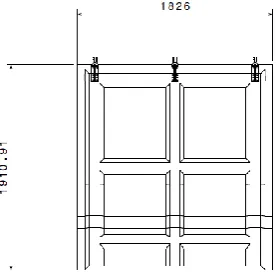
[image:2.595.89.228.131.269.2]3.1 Cad model of main landing gear door panel
Fig- 2. Front view of main landing gear door
[image:2.595.314.549.150.350.2]The material used is T700-12K-50C#2510 Plane weave fabric.
Table 1: allowable for T700-12K-50C
Toray -700-12K-50C#2510 plane weave fabric
Young’s modulus,E11 56003.4mpa
Young’s modulus,E22 54448.8mpa
Poisson ratio, 12 0.0420
In plane shear modulus,G12 4212.23mpa
Density, 1800kg/m3 Allowable stress in tension
in X direction, Xt
853.2mpa
Allowable compressive stress in X direction, Xc
605.3mpa
Allowable tensile stress in Y direction, Yt
677.2mpa
Allowable compressive stress Y direction, Yc
629.1mpa
In plane shear strength, S 124.6mpa Source : T700S Datasheet
The core materials used are HRH-10
Table 2: Allowable for HRH-10 HRH-10(Honeycomb core)
Transverse shear modulus,G1z
930.792mpa
Transverse shear modulus,G2z
372.3mpa
Poisson ratio, 12 0.3
Density, 130 kg/m3 Source : Hex Web Honeycomb attributes
The materials used for solid laminate is T700-12K-50C composite which is plane weave fabric and that for core is HRH-10. The source is been the Toray composite datasheet for solid laminate and that for core is Hex web Honeycomb attributes.
[image:2.595.32.293.334.546.2]4. Fem Description
Figure 3. Fem description of main landing gear door panel
The FE model of the above configuration is built as shown in figure.
FE modelling is done by using 2D quad elements of element size 20mm.
Number of RBE2 = 6 (3 for hinges and 3 for latches).
The composite laminate were represented by PCOMP’S ply layups as shown in table
Slant region of the core is been represented as stepped core.
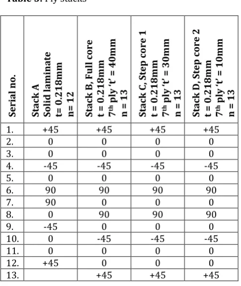
5. Ply layup definition
Ply orientation plays a key role as where we need extra stiffness we tailor the plies more over that region.
Fig -4: Stack ups for panel and core
There is solid laminate and a core which has different ply
Hinge
edge
Trail edge
Latch edge
[image:2.595.308.556.543.741.2]© 2015, IRJET.NET- All Rights Reserved
Page 1367
orientation which is described in the below table:Table 3: Ply stacks
S er ia l no . S ta ck A S olid l a min a te t= 0. 2 18 m m n= 1 2 S ta ck B , F u ll cor e t = 0. 21 8m m 7
th p
ly ‘t ’ = 40 m m n = 13 S ta ck C , S tep co re 1 t = 0. 21 8m m 7
th p
ly ‘t ’ = 30 m m n = 13 S ta ck D , S tep cor e 2 t = 0. 21 8m m 7
th p
ly ‘t ’ = 10 m m n = 13
1. +45 +45 +45 +45
2. 0 0 0 0
3. 0 0 0 0
4. -45 -45 -45 -45
5. 0 0 0 0
6. 90 90 90 90
7. 90 0 0 0
8. 0 90 90 90
9. -45 0 0 0
10. 0 -45 -45 -45
11. 0 0 0 0
12. +45 0 0 0
13. +45 +45 +45
6. Pressure conditions
There are two pressure condition has been analysed which industry generally follow to model any panel of an aircraft, those are:
A. Bursting pressure : The pressure is acting from inside of the cabin to the outside free air is called bursting pressure
Figure 6. Bursting pressure on main landing gear door
[image:3.595.313.539.327.689.2]B. Crushing pressure: The pressure is acting from outside free air to the inside of the cabin is known as crushing pressure.
Figure 6. Crushing pressure on main landing gear door
7.
Results and discussion
Case 1:
For Bursting pressure of 0.2068mpa (3psi)
[image:3.595.318.534.345.513.2]1(a) Stress plot for pandown model is
Figure 7. Stress region for stuffed hat model
1(b) Stress plot for full sandwich core is
Figure 8. Stress region for full sandwich core model
Max stress observed is 355.2mpa for stuffed hat model for burst pressure and for full sandwich core model it is
© 2015, IRJET.NET- All Rights Reserved
Page 1368
2(a) Deformation plot for pandown model isFigure 9. Deformation region for stuffed hat model
[image:4.595.306.550.74.695.2]2(b) Deformation plot for full sandwich core model is
Figure 10
.
Deformation region for full sandwich core Maximum deformation observed for stuffed hat model is 27.44mm and for full sandwich core model is 28.52mm. Deformation is more in full sandwich core model as compared stuffed hat model of MLGD.3(a) Failure index plot for pandown model is
Figure 11. Failure index region for stuffed hat model Failure index is defined by applied maximum strain to the allowable maximum strain which should be less than to one for the safe design.
[image:4.595.310.555.97.248.2]3(b) Failure index plot for full sandwich core model is
Figure 12. Failure index for full sandwich core model. Maximum Failure index for stuffed hat model is 0.565 and for full sandwich core is 0.640. stuffed hat model has got least failure index as compared to full sandwich core model which is very positive sign for this approach of optimizing the weight for MLGD of an Aircraft.
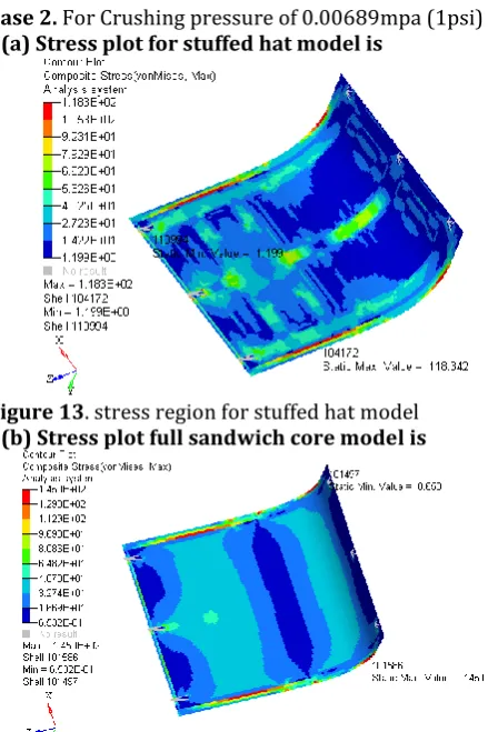
Case 2. For Crushing pressure of 0.00689mpa (1psi)
[image:4.595.50.258.102.277.2]2(a) Stress plot for stuffed hat model is
Figure 13. stress region for stuffed hat model
2(b) Stress plot full sandwich core model is
Figure 14. stress region for full sandwich core model Max stress observed is 118.342mpa for bursting pressure
[image:4.595.314.534.331.661.2] [image:4.595.45.265.538.712.2]© 2015, IRJET.NET- All Rights Reserved
Page 1369
3(a)Deformation plot for stuffed hat model isFigure 14. Deformation region for stuffed hat model
[image:5.595.303.567.291.432.2]3(b) Deformation for full sandwich core model
Figure 15. Deformation for full sandwich core model Maximum deformation for stuffed hat model is 9.142 and for full sandwich core model is 9.378. Stuffed hat model has got least deformation as compared to full sandwich core model.
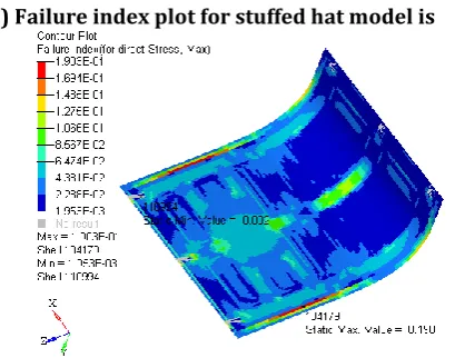
4(a) Failure index plot for stuffed hat model is
Figure 16. Failure index for stuffed hat model
Maximum Failure index for stuffed hat model is 0.190 and for full sandwich core is 0.211. Stuffed hat model has got least failure index as compared to full sandwich core model which shows the advantages of going by this approach to optimize the weight issue for any Aircraft.
4(b) Failure index plot for full sandwich core model is
Maximum Failure index for stuffed hat model is 0.190 and for full sandwich core is 0.211.
Result table
Results Stuffed hat 2D core Full sandwich core Bursting Crushi
ng
Bursti ng
Crushi ng
Stress (mpa) 355.2 118.3 441.1 145.0
Displacement (mm)
27.44 9.142 28.52 9.37
Failure index 0.565 0.190 0.640 0.210
Mass(kg) 33.953 36.521
8. CONCLUSIONS
There has been two pressure condition are analyzed which is Bursting pressure and crushing pressure for the main landing gear door panel and the results are
compared with sandwiched model in terms of stress, deformation and failure index
1. From the Stuffed hat model we observe that, the max stress obtained in the model is 355.2mpa, deformation obtained in the model is 27.44mm and the failure index obtained is 0.525 and also the mass is 33.9kg
2. From the Sandwiched model we observe that, the max stress obtained in the model is 441.1mpa, deformation obtained in the model is 28.52mm and the failure index obtained is 0.640 and also the mass is 36.95kg.
From the above results we can conclude that stuffed hat model shows better results as compared to sandwiched model, it means still there are chances to save the weight for any panel of aircraft and if we able to do this analysis for max number of panel in the aircraft has to used, means we will be able save much of weight in the aircraft so that we can provide number of advantages.
[image:5.595.51.256.496.657.2]© 2015, IRJET.NET- All Rights Reserved
Page 1370
REFERENCES
(1) S.J Lewis, ‘The use of carbon fibre composites on military aircraft’ 7 december 1993
(2) Jiayi Liu, Zhengong Zhou, Linzhi Wu, Li Ma, ‘Mechanical Behavior and Failure Mechanisms of Carbon Fiber Composite Pyramidal Core Sandwich Panel after Thermal Exposure’, May 12, 2012
(3) K. N. Shivakumar, M. J. Sundaresan, and V. S. Avva, ‘Structural Integrity of Discontinuous Stiffened Integrally Braided and Woven Composite Panels’, March 1999
(4) Markus Kaufmann, ‘Cost/Weight Optimization of Aircraft Structures’, February 2008
(5) Wai Chee Mun, Ahmad Rivai, Omar Bapokutty, ‘ Design and Analysis of an Aircraft Composite hinge bracket using Finite Element Approach’, 31 october 2014
(6) J. Eiblmeier, J. Loughlan, ‘The buckling response of carbon fibre composite panels with reinforced cut-outs’, 1995
(7) Ronald Krueger and James Ratcliffe, ‘Analysis of an Aircraft Honeycomb Sandwich Panel with Circular Face Sheet/Core Disbond Subjected to Ground-Air Pressurization’, March 2013