http://www.sciencepublishinggroup.com/j/ajset doi: 10.11648/j.ajset.20190404.12
ISSN: 2578-8345 (Print); ISSN: 2578-8353 (Online)
Challenges and Safety in Erection and Commissioning of
280/85 Tons Single Failure Proof EOT Crane at PFBR
Swamynathan Kudiyarasan
1, *, Poundraj Sivakumar
1, Sanjeevi Umapathi
1,
Malangu Eswaran Sarath Chander
21
Department of Atomic Energy, Fast Breeder Reactor, Bharatiya Nabhikiya Vidyut Nigam Limited, Kalpakkam, India 2
Unique Industrial Handlers Private Limited, Nashik, Maharashtra, India
Email address:
*
Corresponding author
To cite this article:
Swamynathan Kudiyarasan, Poundraj Sivakumar, Sanjeevi Umapathi, Malangu Eswaran Sarath Chander. Challenges and Safety in Erection and Commissioning of 280/85 Tons Single Failure Proof EOT Crane at PFBR. American Journal of Science, Engineering and Technology. Vol. 4, No. 4, 2019, pp. 66-72. doi: 10.11648/j.ajset.20190404.12
Received: September 26, 2019; Accepted: December 8, 2019; Published: December 10, 2019
Abstract:
The Electric overhead traveling (EOT) crane installed in Prototype Fast Breeder Reactor (PFBR), Reactor Containment Building (RCB) is the largest capacity EOT crane installed in any nuclear power plants in India with some unique features of its own. It has been built with a single failure proof concept which is one of the prime requirements of a nuclear facility as per the standards of NUREG/IS. It is a double bridge girder type; the girder used in this crane is a single structure having a length of 34.8m without any joints as designed by IGCAR/BHAVINI (first of its kind). The span of the EOT crane is 33.4m and installed at a height of 42m from the ground level with the lifting height of 42.5m. This crane was manufactured by an Indian company M/s. UNIQUE CRANE, NASIK. Two hooks (280 tons / 85 tons) are connected in the same trolley sharing the Long Travel (LT). Load testing of the complete crane was done at factory before transporting it to PFBR site. The components of the crane were assembled in PFBR site. The erection methodology adopted was distinct w. r. t the site condition, as the components which were handled were very heavy, available space for installation was restricted and the head room was also very less. This erection has been completed successfully and very safely without any notable incidents. This activity is a biggest achievement / milestone in the nuclear industry in India. Later the EOT crane was commissioned, load tested with 350 tons load (negligible deflection) and being operated successfully without any incidents so far. This was achieved by accurate erection procedure, stringent Quality Assurance Plan (QAP), Job Hazard Analysis (JHA) and Safe Operation Procedure (SOP). Many challenges were faced during manufacturing, testing, erection and load testing at site. This paper deliberates those challenges.Keywords: EOT Crane, Single Failure Proof, Bridge Girder, Bogie, Safety, Nuclear Industry, Erection
1. Introduction
The EOT crane inside RCB is designed as per the standard AI-IS; 13834 MECHANISM – M -5 IS: 3177-1999, NUREG-0554 [1] which can handle 280 tons loads. The largest load envisaged to be handled by this crane is the Pump & Intermediate Heat Exchanger (PI) flask along with the Primary Sodium Pump. The PI flask weight around 210 tons and the pump weight around 40 tons. Based on this load, the EOT crane has been designed for 280 tons capacity. Another auxiliary hook having a capacity of 85 tons is also mounted on the same trolley for ease of operation for
handling lighter components and to reduce the time required for operation. The overview of EOT Crane at RCB is shown in Figure 1.
rope system. For aux hoist, however, there is only one rope drum common to both load paths.
Figure 1. Overview of 280/85T EOT Crane in RCB.
The total weight of the crane i.e., girder, trolley and the hook is 385 tons with span of 33.4m [3]. The maximum and minimum hoist speed is 1.5 meter per minute and 0.15 meter per minute respectively. The main hoist lifting height is 42.5 meter and the hook hoisting up/down time is 30 minutes. Similarly, auxiliary hoist lifting height is 55.5 meter and the hook hoisting up/down time is 38 minutes. The EOT crane structure and trolley have been seismically qualified for the purpose of safety during any seismic events. This crane has been provided with an operator cabin in the crane and also a RF (Radio Frequency) remote which helps in operating the crane being near to the load and thus reduces any manual error during communication and signaling. The operation of the crane was found to be very smooth without any noise even now after 7 years of operation. The maximum deflection observed in the crane after commissioning is 9mm where allowable is 37.11mm. This crane was erected in Dec 2011. After seven years, the deflection is only 10 mm. The load test result indicates that the variation in the present deflection observed in the crane as compared to the initial value during commissioning is very less. This crane is also having an interlock with another 15 tons EOT crane which is erected below this crane such that interference of both the cranes will not be there. This giant crane erection and commissioning could be completed successfully & safely only because of adequate planning, following proper sequence of erection, strict adherence to the approved procedures and safety precautions.
2. Bridge Girder
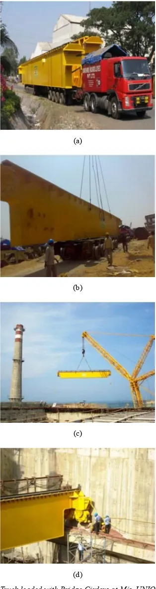
The bridge is box type and consists of two nos. girder which are made of a single metal structure having dimension of (34600 × 1400 × 1480mm) [4-7]. This being the largest girder used in the nuclear plant which was manufactured by M/s. UNIQUE works and transported to the BHAVINI site in single hydraulic truck as show in Figure 2 (a).
After lot of efforts, the girder reached the BHAVINI site without any transit damage as shown in Figure 2 (b). New approach roads were made near the reactor building for normal truck movement. However, many iron plates were provided on the roads to bring the truck near RCB.
(a)
(b)
(c)
(d)
Figure 2. (a) Truck loaded with Bridge Girders at M/s. UNIQUE works. (b) Girder at PFBR site being unloaded. (c) Bridge girder being moved by Leibherr crane, (d) Bridge girder erected on the gantry rail and aligned.
Largest in the country) from M/s. LIEBHERR, GERMANY as shown in Figure 2 (c). The massive girder was positioned and aligned on the RCB gantry at height from the ground 45 meters as shown in Figure 2 (c) & (d).
Similarly, the second girder was also placed on the gantry and accurately aligned within allowable tolerances as shown in the Figure 3 (a). After aligning the bridge girders on the gantry rail, the lifting sling connected to the girder was removed safely by the worker. For approaching the hooking point, a ladder from top of the girder was used and the worker was connected with a rope held by another worker from the top of the platform as the safety belt was not enough to reach that point. General guidelines for removing the slings were available in the procedures. However, the erection team was well coordinated and executed the task successfully as shown in Figure 3 (b). This is one of the challenging task for the engineers at site to work safely without any notable incidents.
(a)
(b)
Figure 3. (a) Second girder being placed on gantry. (b) Safely Lifting slings being removed from hook by using a ladder fixed along the girder (A worker with safety belt being held with rope by another person standing on the top platform of the girder).
3. End Carriage / Bogie
The end carriages generally provided for all the cranes are also called bogie in case of large capacity crane. Each bogie consists of four numbers of wheels to transfer the entire load on the gantry in the RCB as shown in Figure 4 (a). This bogie was assembled before lifting of the girder for ease of alignment of girders as shown in Figure 4 (b).
(a)
(b)
Figure 4. (a) Bogie fixed to the Bridge Girder. (b) Bridge Girder along with bogie being lifted.
4. Trolley with Main and Auxiliary Hoist
The trolley consists of a Main hoist mechanism, Auxiliary hoist mechanism, Gear boxes, Rope drums, brakes etc., The main hoist mechanism is installed on the frame of the main trolley and includes two drum units. The drums are driven by electric motor through reduction gear connected in series. To synchronize the drum rotation, electric motors are connected by means of intermediate shaft. Each intermediate shaft accommodates two electro hydraulic brakes. The main hoist mechanism is equipped with hand drive to bring the load in safe position in case of interruption in power supply.
Main hoist trolley consists of main hoist mechanism, frame, travel mechanism, grapples, brackets, high strength bolts, split housing and axle [8]. The trolley frame rests on four carriages. Each of these carriages is supported by two double flanged wheels. Double flange running wheels are mounted on the wheel shafts running in rolling bearings. A motor reduction gear with its hollow output shaft on wheel shaft. To exclude oil leakage to reactor operating floor tray made of plates in the form of pan is installed under the motor reduction gear.
Auxiliary hoist trolley is connected to the main hoist trolley by means of two hinged joints. Auxiliary hoist trolley travels with the main hoist trolley i.e. it doesn’t have separate drives for movement of auxiliary trolley. Its consists of auxiliary hoist mechanism frame, split axle boxes, bearings, axle, running idle wheels and grapples [9]. Auxiliary trolley wheels are flangeless. Its position on the rail is determined by flanges of the main hoist trolley wheels and hinges connecting the trolleys. The grapples fixed to the trolley are intended to hold trolley on the rails during earthquake. The side surfaces of the grapples function as to determine the extreme position of the trolley while travelling along the bridge.
The main hoist mechanism having one thrust brake and one Electro Magnetic brake. Similarly, auxiliary hoist mechanism is also having one thrust brake and one Electro Magnetic brake. The main hoist is having two rope drums dia. 2270mm, two nos. gear boxes, two nos. motor each rating 150 kW. Whereas, auxiliary hoist is having only one rope drum having dia. 2424mm, two nos. gear boxes, two nos. motor each rating 40 kW. The total trolley size is 6465 x 6625 x 7150mm with a weight of 190 tons. This crane is having two nos. of hooks namely main hook and auxiliary hook. Both are Ramson type. The main 280 tons snatch block hook weight is 22.5 tons and auxiliary hook 85 tons weight is 4.5 tons. The clearance between those two hooks is 1850mm.
Figure 6. Trolley assembly being placed with the hooks on the bridge girder rails.
The rope is reeved around having 3.6 km length and 16 falls for main hoist and 8 falls for auxiliary hoist. These were completed in ground where trolley is assembled near RCB as shown in Figure 5. The whole trolley was assembled and it has been lifted with the heavy-duty crane and placed on the bridge girder rails as shown in Figure 6.
5. Safety Features
The main and aux. Hoist system of the crane is equipped with dual load path system. Thus, in the event of failure of any component on one of the two load paths, the other load path will take over without any uncontrolled movement of load. Each load path is provided with a separate drum, gearbox, motor, brake and a rope system. For Aux Hoist, however, there is only one rope drum common to both the load paths. The wire ropes are designed with factor of safety 12 when both the load paths are intact. In case of failure of one load path, wire
rope will have a factor of safety 6.
Sheave block assembly is designed with protective guard in such a way that the sheaves will not separate out and fly-off in the event of breakage of sheave pin. Each Main and Aux hook block is provided with dual attaching points if one attachment fails, the other will support the load.
Drum anti fall arrangement is provided below each rope drum, such that the rope drum will rest over the support in the event of breakage of drum shaft. Each hoisting motion is provided with load cell arrangement to protect against overloading and also give audio-visual alarm in case one of the load paths fails.
Main Hoist motors will have pulse encoders for feedback to drive module so as to synchronize the speeds of dual paths. In case of Aux Hoist, as the two load paths are connected by a single rope drum, such synchronization is not necessary. However, pulse encoders are provided for aux hoist motors also.
Encoders will also sense over speeding of Rope drums in lowering direction beyond the designed speed and will bring the hoist motion to halt by tripping the electrical circuit. Each load path will be provided with over hoisting and over lowering limit switches with inbuilt slow down limit switches. Apart from the above, two blocking system is also provided to prevent over hoisting to avoid physical contact of load block with top obstruction. Load cell activation and motor over current sensing is integrated to safe guard the system during load hang up. The suitable guide rollers / derailment guards are provided for trolley and end carriages of crane to prevent derailment during seismic event as shown in Figure 7.
Suitable parking lugs/ rail clamps arrangements are provided for trolley and crane for parking the crane. Manual release of brakes during emergency lowering is provided. There are inherent safety features for motors for monitoring and fault report systems.
The control system is provided with PLC (Programmable Logic Control) to oversee and monitor the operation of various motions of the crane and take corrective measure to run the crane safely.
(a)
(b)
Figure 8. (a) Bogie wheels being placed on the gantry rail, (b) LT free movement after placing on the gantry.
Gantry rail having width of 120mm and the wheel width is 150mm. A smooth LT movement achieved with this clearance was the one of the challenging task and the same is shown in Figure 8 (a) and (b) [10].
6. Erection Methodology
Any incident/accident would happen only when any safety procedures are violated. Strict adherence to the approved procedures was followed at all stages of erection and commissioning of the EOT crane. An error free erection procedure (SOP) is including the following.
1.An overall detail of the work intended to be carried out. 2.Safety PPEs and procedures to be used for each step/job
to be carried out.
3.Pre-job briefing to be given to each level of workers before starting any activity.
4.Hazard/risk involved in each step to be made aware to each level of workers.
5.Checklists to be filled wherever applicable before starting any activity.
6.Sequential work activity track sheet involving many agencies.
7.Post job debriefing.
Any violation in the procedure will be easily found by integrating with the other parallel procedure. Procedure should be able to find immediately when there is a violation. Any single minor incident shall be identified with the other
procedure being executed for the same work. Hence a safe Operating procedure has been adopted.
It can be split in to two, a Macro SOP and a Micro SOP. The SOP prepared in micro and macro form shall be knitting with each other, such that any violation or shortfall in any of the SOP will be easily identified by the other SOP [11-15]. Each step will be doubly ensured by using micro and macro SOPs. This procedure will take more execution timing but has zero failure.
7. Commissioning and Load Test
The commissioning of the control panels were done stage by stage in a sequential and safer manner. All the panels were shifted over the girder and are located in one of the bridge girder pathway. Manual approach to these panels in the middle of the girder at higher elevation was challenging every time. Tuning of the drives was challenging as one person should be in the motor side and another person in the panel area. Communication and coordination at a height of 40 meter from the ground was challenging.
The RCB floor area was designed for 20 tons per square meter area. 350 tons load was placed in a special structure to keep the loads uniformly distributed. Plates were placed on the ground. A special cradle was fabricated at site for load testing due to the space constraints. The full load test of 280 tons and over load test of 350 tons has been completed with the main hook as shown in Figure 9. The load test of the inner hook (dia. 180mm and width of 320mm) i.e. Eye hook was very challenging. The inner hook was tested with a small pin (dia. 180mm and 1130mm length), four slings and two nuts as show in Figure 10.
It was specially designed by site and manufactured by M/s. UNIQUE, was vital and successfully tested at factory. The same pin is connected on the inner hook and over load test with 350 tons also completed. This was one of the major achievements.
Figure 10. The Eye hook and pin with cradle arrangement for testing of 350 tons.
Finally, the crane lifted the PI flask load 230 tons successfully and placed on reactor vault as shown in Figure 11. The actual hook approaches in all the sides are well within the
dimensions mentioned in the drawings and the same has been tabulated in Table 1.
Table 1. 280/85 tons crane hook approaches.
Long Travel Right (West) mm Left (East) mm Cross Travel Forward (South) mm Reverse (North) mm
As per Design 3300 1940 As per Design 4100 3800
Measured at Site 3300 1927 Measured at Site 4040 3940
Figure 11. PI Flask (230 tons) lifted inside RCB.
8. Lesson Learnt and Recommendations
Trolley can be assembled at ground level itself. So that all motors, gears and rope reviving could be done. Then the special lifting structure was designed at site. Hence the total
weight of the trolley comes around 360T and the same was erected by using Leibherr crane. Initially this was not expected. For dismantling and removal of gear box, motor etc. during maintenance, no provision exists above the EOT. Hence on the roof of RCB, a hoist/mono rail shall be provided. For load testing the inner hook, special arrangement is required. Site has designed the small pin, manufactured by M/s. UNIQUE and firmly load tested with the crane.
85 tons hoist operation speed may be increased because when compared to 280 tons and 15 tons hoist operation, it is very slow. Hook approach is not enough on all the side of the building. The above points may be treated useful for design the cranes for Fast breeder Reactors (FBR-1 and FBR-2).
9. Conclusion
place, it was accomplished without any safety issues / incident which were very challenging.
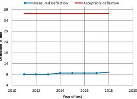
Figure 12. Deflection results of 280/85 tons crane for the last 7 years.
Despite the allowable deflection limit of 37.11mm (for a Span (33.4m) / 900 = 37.11mm) as per the standards, a deflection of just 9mm was achieved which was least. Subsequently after 7 years of operation, the deflection as measured is only 10mm which is hardly an increase of 1 mm as shown in Figure 12.
The result of the stringent requirement in the design, material selection, manufacturing and factory testing of this huge EOT crane has met all the tolerances as expected with standard. Nevertheless, proper adherence to all the safety precautions, procedures like JHA, SOP etc., at PFBR site during erection, commissioning and testing has proved this giant lifting machine to be rugged, robust and highly reliable making us gain more confidence on our large component handling, erection, commissioning and operational methods.
References
[1] L porse (1979), Single failure proof cranes for nuclear power plants. U. S. Nuclear Regulatory Commission, NUREG -0554.
[2] Dong Hun Lee, Sang Jin Kim, Man Seung Lee, Jeom Kee Paik (2019). Ultimate limit state based design versus allowable working stress based design for box girder crane structures. Thin-Walled Structures 134 (2019) 491–507.
[3] Omkar K. Sakurikar, D. V. Kushare (2016), Review of Overhead Crane and Analysis of Components Depending on Span, IRJET, Volume: 03 Issue: 05 | May-2016 pp 1004-1008.
[4] M. Gohil, “Optimum Design of Bridge Girder of an EOT Crane Structure”, Institute of Technology, Nirma University, Ahmedbad-382481, 25-27, November 2009.
[5] Patel Khalidurfeasif, Deepali Bharti (2015). Finite Element Analysis Of 450T EOT Crane Box Girder, International Journal of Advance Engineering and Research Development Volume 2, Issue 11, November -2015 pp 171-178.
[6] Gianni Niccolini, Giuseppe Lacidogna, Alberto Carpinteri (2019). Fracture precursors in a working girder crane: AE natural-time and b-value time series analyses. Engineering Fracture Mechanics 210 (2019) pp 393–399.
[7] Abhinay Suratkar, Vishal Shukla, Dr. K. S. Zakiuddin (2013). Design Optimization Of Overhead EOT Crane Box Girder Using Finite Element Analysis, International Journal of Engineering Research & Technology (IJERT), Vol. 2 Issue 7, July – 2013.
[8] Dhaval H. Kanjariya (2015), A Review on Design and Analysis of Hoisting Machinery in EOT Crane, IJSRD - International Journal for Scientific Research & Development| Vol. 3, Issue 02, 2015.
[9] Mr. Swapnil K. Agrawal, Mr. Vaibhav H. Bankar (2016), Design of Components used in Hoisting Mechanism of an EOT Crane: A Critical Literature Review, International Journal of Engineering Technology, Management and Applied Sciences, December 2016, Volume 4, Issue 12.
[10] Leszek Sowa, Zbigniew Saternus, Marcin Kubiak (2017), Numerical modelling of mechanical phenomena in the gantry crane beam, XXI International Polish-Slovak Conference “Machine Modeling and Simulations 2016”. Procedia Engineering 177 (2017) pp 225 – 232.
[11] Vinay Dubey, Rajiv Premi, (2016). Hazard Identification of cranes and their control measures, © 2016 IJEDR | Volume 4, Issue 1 pp 504-509.
[12] Vinay Dubey, Praveen Patel (2015). hazard identification and their control in lifting machinery. Int. J. of Engg. Sci. & Mgmt. (IJESM), Vol. 5, Issue 2: April-June: 2015, 1-4.
[13] Stian Ruud, Age Mikkelsen,” Risk-based rules for crane safety systems”, Reliability Engineering and System Safety 93 (2008) 1369–1376.
[14] Zhiping Chen, Zhewei Li, Chaoliang Huang, Guoan Zhang, Huanwei Yu,” Safety Assessment Method of Bridge Crane Based on Cluster Analysis and Neural Network”, Procedia Computer Science 131 (2018) 477–484.