LABVIEW BASED SOFTWARE-DEFINED PHYSICAL/MAC LAYER ARCHITECTURE FOR
PROTOTYPING DENSE LTE NETWORKS
Rohit Gupta ([email protected])
1, Bjoern Bachmann ([email protected])
1, Andreas Kruppe
([email protected])
1, Russell Ford ([email protected])
2, Sundeep Rangan
([email protected])
2, Nikhil Kundargi ([email protected])
3, Amal Ekbal
([email protected])
3, Karamvir Rathi ([email protected])
3, Arash Asadi ([email protected])
4,
Vincenzo Mancuso ([email protected])
4, and Arianna Morelli ([email protected])
51
affiliation: National Instruments, Dresden, Germany
2affiliation: NYU Wireless, New York, USA
3affiliation: National Instruments, Austin, USA
4
affiliation: IMDEA Networks, Madrid, Spain
5affiliation: INTECS, Pisa, Italy
ABSTRACT
We propose to adopt and extend the Software Defined Net-working (SDN) paradigm to manage interference within dense heterogeneous deployments of wireless network cells. Specifi-cally, we present a network architecture and the initial research results we have achieved by using software-defined physical and MAC layers to build a small scale LTE testbed. To build the testbed presented in this paper, we have used LabVIEW and the open-source NS-3 LENA LTE stack for real time emulation of dense deployments. The testbed has been designed to serve as a powerful validation and demonstration tool for algorithms pro-posed within the framework of the CROWD project for tack-ling the challenges of dense and heterogeneous wireless deploy-ments.1 Our testbed specifically allows to study the performance
of cross layer PHY/MAC control algorithms within a realistic cellular environment.
1 INTRODUCTION
Mobile data traffic demand is growing exponentially and the trend is expected to continue for the near future, especially with the deployment of 5G networks. In order to cope with such rapid explosion of traffic demand, mobile network operators have al-ready started to push for denser, heterogeneous deployments. However, interference due to uncoordinated resource sharing techniques represents a key limiting factor in the design of dense wireless networks, where resources are limited due to either the costs for licensed bands or the proliferation of hot spots in license-exempt bands.
1CROWD (Connectivity management for eneRgy Optimised Wireless Dense
networks) is a research project funded by the European Commission in the Sev-enth Framework Programme.
This situation calls for the deployment of agilenetwork con-trollers, with the aim of orchestrating the utilization of wiless and backhaul resources, to achieve efficiency in both re-source utilization and energy consumption. Indeed, in the FP7 CROWD project [1] we have shown how a Software-Defined Networking (SDN) based approach can be suitably adopted to design the next generation of dense wireless mobile networks. The CROWD approach is based on a two-tier control architec-ture oflocalorregionalcontrollers, which enables the required level of flexibility and reconfigurability, while at the same time providing energy-efficient network infrastructure for both the ra-dio access and the backhaul. However, to demonstrate and vali-date, in a realistic framework, architectural and algorithmic so-lutions such as the ones proposed in CROWD, it is needed to design and deploy SDN prototypes that tackle the challenges of dense and heterogeneous wireless deployments. Moreover, to be able to implement novel and flexible network control functions in real wireless devices, the prototyping has to involve Software Defined Radio (SDR) techniques.
la-tency backplane which can be scaled up/down depending on the compute needs of the communication system.
There have been quite a few SDR platforms around, see Gnu-Radio [4], BEECube [5], Nutaq [6] and SORA [7]. However, we chose LabVIEW due to its integrated graphical system design and ability to integrate PHY/MAC designs within a single envi-ronment, with the possibility to develop suitable APIs for SDN control applications. LabVIEW can be run seamlessly on GPPs to write MAC/Higher layers, while at the same time can be used to build high throughput/low latency signal processing blocks for physical layer. LabVIEW seamlessly runs on a wide range of high-end PXI [8] based products that can meet the needs of large processing capabilities, and can also be simultaneously de-ployed towards USRP based products [9], which are more com-pact and cost-effective. LabVIEW allows the same source code to transition efficiently towards both the hardware targets (PXI and USRP) to meet communication needs of the researcher, thus allowing end end user to scale the system for wide-variety of ap-plications.
As concerns LTE experimental platforms, there are already existing LTE designs [10, 11], but we chose to implement basic building blocks in LabVIEW so we could incorporate config-urability/modifiability aspects into the design at an early stage. LTE standard is much more complex compared to WiFi, and minor changes in for instance physical layer can lead to incom-patibilities at higher layers and vice versa. Hence, we based our design on LTE parameters but implemented only a subset con-sidering the behavior we want to investigate, which is primar-ily focused on creating dense LTE-like environment and study-ing the interference-limited scenarios within a lab environment. The main motivation of this paper is to evaluate the architec-ture of general purpose LTE-like general purpose physical layer written in LabVIEW which is intuitively modifiable due to the graphical design environment offered by LabVIEW. The design also hides the RF/Inter-FPGA/FPGA-Host Communication thus allowing a researcher to focus on the algorithm rather than the complex and demanding integration aspects of SDR prototyp-ing. The current paper builds on our earlier work [12], in which we presented overall system architecture to build LTE testbed us-ing SISO OFDM Physical Layer written in LabVIEW and NS-3 LENA stack [13].
The main contribution of this paper is to describe the de-sign of physical layer architecture and illustrate the config-urable/modifiable aspects of our approach. We build on our previous work [12] and give an overview of the L1-L2 API, which allows interfacing the physical layer with external proto-col stacks. We also illustrate use cases of dense small cell pro-totyping, which can be emulated over such a testbed. Some of these use cases are being studied both experimentally and the-oretically within the context of CROWD project. Finally, we present initial results for rate-adaptation/multi-user scheduling which serve as a building block to conduct future experiments to explore the design space for SDN.
The paper is organized as follows. Section 2 introduces the
!"#$%&'()*+,-./&) 0"#121) 0"#34%,56-7) *44)*44) *44) *44) *44) *44) *44) *44) *44) *44) *44) *44) *44) *44) *44) *44) *44) *44) *44) *44) *44) *44) *44) *44) *44) *44) *44) *44) *44) *44) *44) *44) *44) *44) *44) *44) *44) *44) *44) *44) *44) *44) *44) *44) *44) *44) *44) *44) *44) *44) *44) *44) *44) *44) *44) *44) *44) *44) *44)*44)*44)*44)*44)
*44) *44) *44) *44) *44) *44) *44) *44) *44) *44) *44) *44) *44)*44) CRC !"!# 0"#121) !"!# 0"#34%,34%, Backhaul "8&9'8:6) ;8,8+%;%,<) 121) 468&%;%,<) =) $-4-6-+>) ?@.&-A%B>)8,?) ;-,@<-B@,+) 0"#CDE0) 0"#CDE0) 0"#CDE0)
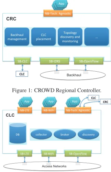
Figure 1: CROWD Regional Controller.
!"#$%&' !"#()*)' !"#%+,-.'/01234,'
5"#$%&' 5"#()*)' 5"#67+1*829' ,288+,:2;' <;2=+;' >)3,2?+;@' A"' /77'/77' /77' /77' /77' /77' /77' /77' /77' /77' /77' /77' /77' /77' /77' /77' /77' /77' /77' /77' /77' /77' /77' /77' /77' /77' /77' /77' /77' /77' /77' /77' /77' /77' /77' /77' /77' /77' /77' /77' /77' /77' /77' /77' /77' /77' /77' /77' /77' /77' /77' /77'
/77'/77'/77'/77'/77' /77' /77' /77' /77' /77' /77' /77' /77' /77' /77' /77' /77' /77' /77' /77'
/77'/77' /77'/77'/77'/77'/77'/77'/77'/77'/77'/77'/77'/77'/77'/77'/77'/77'/77'/77'/77'/77'/77'/77'/77'/77'/77'/77'/77'/77'/77'/77'/77'/77'/77'/77'/77'/77'/77'/77'/77'/77'/77'/77'/77'/77'/77'/77'/77'/77'/77'/77'/77'/77'/77'/77'/77'/77'/77'/77'/77'/77'/77'/77'/77'/77'/77'/77'/77'/77'/77'/77'/77'/77'/77'/77' /77'/77'/77'/77'/77'/77'/77'/77'/77'/77'/77'/77'/77'/77'/77'/77'/77'/77'/77'/77'/77'/77'/77'/77'/77'/77'/77'/77'/77'/77'/77'/77'/77'/77'/77'/77'/77'/77'/77'/77'/77'/77'/77'/77'/77'/77'/77'/77'/77'/77'/77'/77'/77'/77'/77'/77'/77'/77'/77'/77'/77'/77'/77'/77'/77'/77'/77'/77'/77'/77'/77'/77'/77'/77'/77'/77'
CLC
!"!# !$!#
+,-.'/01 +,-.'/01'/01234,'/01234,
5"#$%&'
5"#$%&' 5"#5"#()*)()*) 67+167+1
Access Networks
Figure 2: CROWD Local Controller.
CROWD architecture that serves as the basis for our work. We also highlight in this section how we plan to integrate CROWD SDN controllers into our PHY/MAC framework. Section 3 in-troduces the high level API messages that enables software-defined aspects of the proposed physical layer and lends itself to be programmable through SDN controllers via higher layers of LTE protocol stack. Section 4 describes the implementation aspects of high throughput LTE Downlink PHY layer that also has building blocks to implement LTE Uplink. Section 5 de-scribes the use cases that we plan to target to demonstrate the SDN concepts within the framework of CROWD project. Sec-tion 6 describes initial results for physical layer calibraSec-tion and initial experiments that we have conducted in the lab settings. Finally, we conclude the paper with future work and next steps in section 7.
2 CROWD ARCHITECTURE
3G, LTE, WiFi), cell ranges (e.g., macro-/pico-/femto-cells), but also at density levels (e.g., from macro-cell Base-Station (BS) coverage in underpopulated areas to several tens or hundreds of potentially reachable BS in hot spots). Such heterogeneity also creates high traffic variability over time due to statistical multi-plexing, mobility of users, and variable-rate applications. In the following, we first give a brief overview of the CROWD control architecture; subsequently we dig into the control of LTE eNBs, with focus on real implementation of both network controllers and controllable-devices for LTE.
2.1 A two-tier control architecture
In order to achieve optimal performance most of the times, re-configuration of the network element is required at different time scales, from very short intervals (few tens of millisec-onds) to relatively long periods (few hours), affecting the de-sign of backhaul and RAN components. In order to tackle the complex problem of reconfiguration, we propose to follow an SDN-based approach for the management of network elements as shown in Figs. 1 and 2. Network optimisation in the pro-posed architecture is assigned to a set ofcontrollers, which are virtual entities deployed dynamically over the physical devices to control the activity of a group of close-by cells on short time scales (CLC—CROWD Local Controller) or the activity of sev-eral groups of cells at macro level at medium/long time scales (CRC—CROWD Regional Controller). These controllers are technology-agnostic and vendor-independent, which allow full exploitation of the diversity of deployment/equipment charac-teristics. Controllers expose anorthbound interface, which is an open Application Program Interface (API) to thecontrol appli-cations. We definecontrol applicationas the algorithm that ac-tually performs the optimization of network elements, for exam-ple the control algorithm for driving Almost Blank Sub-Frame (ABSF) decisions [14]. Thenorthbound interfacedoes not need be concerned with either the details of the data acquisition from the network or the enforcement of decisions. Instead, a south-bound interfaceis responsible for managing the interaction be-tween controllers and network elements. Fig. 1 shows the archi-tecture of a CRC and its interfaces towards control applications and network elements, for instance towards other controllers (via a CLC-specific southbound interface), routers (via OpenFlow), and switches (via IR2S) present in the backhaul. At the local level, CLC shown in Fig. 2 is responsible for the direct control of network elements in the access network via tech-specific south-bound interfaces (e.g., LTE eNBs, WiFi devices, etc.).
2.2 Controlling the LTE eNB
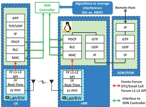
In Fig. 3, we illustrate in more detail how proposed SDN con-trollers (i.e., CLCs, in this specific case) interact with LTE MAC/PHY interface of an LTE eNB to collect statistics regard-ing link performance in terms of throughput, channel state infor-mation, etc., while at the same time proposing eNB behavioral
Remote Host
MAC RLC PDCP
eNB IP UDP GTP
IP UDP GTP IP
SGW/PGW
LV PHY LV Real-Time
FF L1-L2 API MAC
RLC PDCP
IP TCP/UDP
APP
LV PHY LV Real-Time
UE FF L1-L2
API
Femto Forum (FF)/Small Cell Forum L1-L2 API
Interface to SDN Controller SDN
Controller
Algorithms to manage interference (for ex. ABSF)
Figure 3: LTE MAC/PHY SDN Architecture for CLC controlling eNBs.
changes via a controller-MAC Scheduler API. In general, a CLC controller interacts with the MAC layer of eNBs to influence pa-rameters related to scheduling; however, this interface can be easily extended to higher layer of protocol stack. It should also be noted that CLC interfaces can be also be extended to inter-face with UE protocol stack, however this results in the usage of LTE air interface for interaction of SDN Controller/UE pro-tocol stack and the benefits of such SDN application scenarios should be carefully investigated. In general, the currently im-plemented CROWD architecture allows SDN controllers to in-teract only with eNBs and not UEs, so as to minimize changes to UE standards. However, we have proposed a general-purpose architecture that could enable future use cases in which SDN controllers interacts with both eNB and UE.
To enable flexible utilization of LTE PHY and resource al-location mechanisms, we could not rely on commercial de-vices, since they do not come with standard APIs that would allow access to the eNB scheduler and protocols, and so en-able dynamic reconfiguration of the eNB. Instead, we have im-plemented a general-purpose PHY/MAC interface using Small-Cell Forum L1-L2 API [15], and we have deployed the funda-mental LTE PHY and resource allocation schemes in FPGA, us-ing LabVIEW-based NI PXI platform. The L1-L2 API allows integration of the standard LTE protocol stack with the proposed PHY/MAC architecture. The specifications of API and their im-portant features are described in Section 3.
3 GENERALIZED LTE MAC/PHY INTERFACE ARCHITECTURE
In this section, we describe the generalized LTE MAC/PHY interface architecture. Since, we are developing the LTE MAC/PHY interface for prototyping both eNB/UE, it is impor-tant that we exploit commonalities in such interface. In this pa-per, we focus more on downlink MAC/PHY interface, however, we plan to extend this description to include uplink as well. We also point out the commonalities/differences between UL/DL MAC/PHY interface for eNB/UE. Fig. 3 illustrates the posi-tioning of MAC/PHY interface within the overall architecture. We describe the list of important messages that are exchanged between MAC/PHY interface of eNB/UE to allow closed-loop interaction between eNB/UE. We have used Small Cell Forum eNB L1-L2 API [15] as a basis for designing our API, while proposing extensions for allowing the usage for this API at the UE side as well. It should be noted here that the goal of our testbed is for research purposes only to allow flexibility and ease of use for researchers to integrate their algorithms into our testbed. It is in this context that we have made simplifications to the API and even extended it to accommodate more generalized MAC/PHY Architecture for eNB/UE Uplink and Downlink con-trol/data channels. The LTE standard as a whole is quite com-plex and it is prohibitive to implement all the features and sce-narios for both eNB/UE. Hence, we focus on specific use cases described in Section 5 to allow for experimentation of scenarios for dense small cells prototyping within an indoor lab setting along with usage of SDN Controllers, for example CROWD Lo-cal Controller (CLC) or some other distributed/centralized ap-proaches for managing such interference. The API description below should be interpreted in this regard and not with respect to strictly implementing LTE standard to fulfill the requirements for the commercial end-products.
1. PHY_CONFIG_REQ: This message is sent once per ini-tialization from MAC to PHY and configures the follow-ing parameters of the eNB physical layer (cell ID, RF Fre-quency, cell bandwidth, MIMO Configuration). In the case of UE, the UE configures its DL PHY interface to the above parameters to allow synchronization to specific (cell ID, RF Frequency, cell bandwidth, MIMO Configuration). This results in avoidance of complex cell search at the UE side, while at the same time, allows the creation of interference-limited environment within indoor lab setting by config-uring different eNB-UE pairs with different cell IDs/RF Frequencies. The configuration of cell-ID implies specific Primary Synchronization Sequence (PSS), Secondary Sy-chronization Sequence (SSS), Reference Symbol (RS) lo-cation and sequence, thus allowing eNB/UE to synchronize to each other and create a cell. The uplink parameters in this message are initialized in direct relation to downlink parameters.
2. START_PHY_REQ: This message starts the PHY layer
and is always sent by the MAC layer.
3. STOP_PHY_REQ: This message stops the PHY layer and is always sent by the MAC layer.
4. RESET_FRAME_REQ: This message is sent by the pro-tocol stack of eNB/UE to reset the system frame counter of the PHY. This message is sent once after initialization of protocol stack to synchronize MAC/PHY modules. We assume in our testbed that MAC layer is the master of the PHY.
5. SUBFRAME_IND: This message is sent by the PHY to MAC interface every TTI (1ms), and contains current sys-tem frame/subframe number to enable continuous synchro-nization between PHY/MAC modules. This message al-lows the corresponding PHY/MAC modules to correct the time drift which occurs due to the fact that PHY layer is implemented in FPGA, whereas MAC layer resides on General Purpose Processor (GPP), each having their own clock drift. Each subframe indication message for the UE also contains the SINR of received PSS/SSS Synchroniza-tion signal, which is then passed to higher layers with MAC/PHY API to allow for the serving cell measurements.
6. TX_REQ: This message is used by the eNB/UE proto-col stack to pass MAC Control/Data PDUs to the PHY layer for transmission. In case of eNB, it contains a list of DCI (Downlink Control Information) message that carry scheduling information along with associated MAC PDUs. In case of UE, it contains the UCI (Uplink Control Infor-mation) message along with associated MAC payload.
7. RX_IND: This message is sent by the PHY to eNB/UE pro-tocol stack and indicates the received PHY Control Chan-nels and MAC PDUs. It also contains the SINR of received packet.
8. MEAS_CONFIG_REQ: This message instructs the PHY to synchronize to neighboring cells and make measure-ments. The PHY layer is stopped during this pro-cedure. The message contains following parameters: start/end duration of measurement, cell ID, center fre-quency, bandwidth and MIMO configuration. These pa-rameters are enough to make the necessary neighboring cell RSSI/RSRP/RSRQ measurements. Such measurements are the key enabler for Enhanced Inter-Cell Interference Coordination (eICIC) algorithms [16].
9. MEAS_REPORT_IND: This message is sent by the PHY to the MAC layer as a results of status report indication in response to neighboring cell measurements made by
10. SRS_CONFIG_REQ: This message sent by UE MAC to PHY interface to enable Sounding Reference Signal (SRS) configuration that is used to measure uplink signal quality from the users within a cell.
11. SRS_REPORT_IND: This message is sent by the eNB PHY to MAC layer and contains the SRS reports contain-ing uplink measurements.
12. ENABLE_SYNCHRONIZATION_REQ: This message is used to synchronize multiple eNB protocol stacks. This message allows synchronized execution of protocol stacks thus allowing synchronization at the granularity of TTI (1ms) at the MAC layer. This feature is one of the key en-ablers for eICIC algorithms which require multi-eNB syn-chronization, for example ABS. Such synchronization can be achieved using NI-TimeSynch module [17], which can be configured to use either IEEE 1588 PtP protocol [18] that runs over Ethernet or using GPS as the external clock source. The methods mentioned above achieve different levels of synchronization, however the requirement for syn-chronization at the PHY layer requires that different down-link signals arrive within cyclic prefix duration, which is 4.7 us for normal duration and 16 us for extended duration. Since, the uplink is always synchronized to the downlink signal, this automatically results in the synchronization of uplink signal as well.
13. DL_POWER_CONFIG_REQ: This message is sent from eNB MAC to PHY to configure the power of Reference Symbols (RS), PSS, SSS, Control/Data channels, thus al-lowing different power levels neighboring cells to cre-ate/reduce neighboring cell interference.
14. UL_POWER_CONFIG_REQ: This message is sent from UE MAC to PHY to configure the UE transmit power for uplink transport channels.
4 PHY IMPLEMENTATION
This section gives a brief overview of the functional partitioning into LabVIEW real-time host code and LabVIEW (LV) FPGA code as shown in Fig. 4. The transmitter (TX) part is split into a host application and one FPGA board. The receiver (RX) is utilizing two FPGA boards, one for the base-band processing and the other one for decoding the data, and a host application as well. The communication between the LV real-time appli-cation (host) and the FPGA board (target) is done by using LV elements, called host-to-target (H2T) and target-to-host (T2H) FIFOs. For the inter-FPGA communication, we use peer-to-peer (P2P) FIFOs.
4.1 Transmitter design
The overview of transmitter design is shown in Fig. 4(a). A detailed view of the TX RT Host implementation is shown in
Fig. 5, and the detailed view of TX FPGA implementation is shown in Fig. 6.
4.1.1 TX_RT_A - MAC Service Thread
This thread receives UDP packets with the L1-L2 API messages from the MAC layer and parses them. According to the content of those UDP packets the Control Channel (CCH) and Shared Channel Transport Block (SCH TB) queues are filled.
4.1.2 TX_RT_B - TB Generation Thread
This thread runs every millisecond and is triggered by the in-dication of TX FPGA. The Thread is reading from the queues filled by the MAC Service request. After reading the data from the CCH queue the DCI message is built and written to the DCI MSG H2T FIFO. The Xilinx channel encoder parameters are calculated and written to the SCH Encoder H2T FIFO. The re-source mapper configuration is generated and written to the Re-source map H2T FIFO. This thread also transfers the SCH TB
(a) Transmitter (b) Receiver
Figure 5: Detailed view of TX Host Architecture
data from the SCH TB queue (RT) to the H2T FIFO as well.
4.1.3 TX_FPGA_A - CCH loop
The DCI message is read from the DCI MSG H2T FIFO and fed to a Xilinx convolution encoder. Afterward, the data is inter-leaved and QPSK mapped. Finally, the mapped data is written to the CCH IQ FIFO.
4.1.4 TX_FPGA_B - SCH loop
The parameters for the Xilinx LTE DL Channel encoder are read from SCH Encoder H2T FIFO. This data configures the Encoder and after the configuration the SCH TB H2T FIFO is read and the data is fed to the Encoder. The setup and data transfer to the Encoder is controlled by the SCH Encoder FSM. The en-coded data is now scrambled with the "Gold Code" followed by QAM mapping. The mapped data is then sent to the appropriate UE SCH IQ queue. The code scrambling and QAM mapping is controlled by theScrambling Modulation FSM.
4.1.5 TX_FPGA_C - Resource mapping
The module maps the different IQ data according to the resource map.
4.1.6 TX_FPGA_D - IFFT and resampling
Here the TX IQ data is fed to the IFFT and afterwards resampled to the DAC rate of the RF FAM module.
4.2 Receiver design
The receiver design, as shown in Fig. 4(b), is explained in the following subsection in more detail. A detailed view of RX base-band FPGA implementation is shown in Fig. 7. The detailed view of RX decoder FPGA implementation is illustrated in Fig. 8. Finally the details of the RX RT Host implementation are shown in Fig. 5.
Figure 6: Detailed view of TX FPGA Architecture
4.2.1 RX_BB_FPGA_A - Synchronization
The received IQ data is fed through a Low pass filter and deci-mate block. This signal goes to a Correlator bank and afterwards there is the PSS peak detection. This information is then used to update the timing offset for the synchronization.
4.2.2 RX_BB_FPGA_B - CFO Compensation
The received IQ data if fed trough another Low Pass Decimate block to estimate the CFO (Carrier Frequency Offset) phase. The segmented OFDM symbols are now compensated with this estimated value.
4.2.3 RX_BB_FPGA_C - Channel Equalization
The segmented OFDM symbol are then passed through FFT, and then the pilots are extracted, the channel is estimated and the data is compensated by the Channel estimation values. The result is stored in a Peer-to-Peer (P2P) FIFO and transferred to the RX Decoder FPGA.
4.2.4 RX_DEC_FPGA_A - Separate SCH and CCH IQ data
Figure 7: Detailed view of RX base-band FPGA Architecture
4.2.5 RX_DEC_FPGA_B - CCH Decoding
The CCH IQ data is now demapped, descrambled and decoded. The content of the decoded DCI message is evaluated and passed to the DCI message FIFO.
4.2.6 RX_DEC_FPGA_C - Preparing SCH Decoding
With the decoded DCI information, the SCH IQ data is demapped according to the used RBs. The UE specific SCH IQ data is written to a FIFO. The SCH decoder control and LLR FSM control parameters are written to FIFOs as well.
4.2.7 RX_DEC_FPGA_D - SCH descrambling
Now the SCH data is demapped and decrambled usign the LLR algorithm.
4.2.8 RX_DEC_FPGA_E - SCH TB decoding
The descrambled SCH TB data will now be decoded with a Xil-inx LTE DL Channel decoder. The status of the SCH decoding as well as the decoded SCH data is written to T2H FIFOs.
4.2.9 RX_RT_A - SCH Transfer Thread
The status of the SCH decoding is read every millisecond by the Host application. If SCH TB data is available it is read from the SCH TB data T2H FIFO and transfer together with the SCH status information to the higher layers using a UDP connection.
5 USE CASES
In this section, we describe few important use cases that we aim to demonstrate using the proposed testbed architecture. The use cases below serve as a guiding principle for the MAC/PHY ar-chitecture and in future we want to further develop the proposed HW/SW architecture to serve the needs of these use cases. We believe these use cases are fundamental to solving the
spec-Figure 8: Detailed view of RX Decoder FPGA Architecture
Figure 9: Detailed view of RX Host Architecture
tral/energy efficiency, dense networks architectural challenges for the next generation wireless networks.
5.1 LTE ICIC/eICIC Algorithms
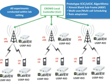
pro-posed 3GPP eICIC mechanism that mitigates the inter-cell in-terference by assigning resources such that some base stations produce blank subframes, thus preventing their activity when the interference exceeds a threshold. Our proposal is designed to be implemented in the CLC, which is in charge of acquiring the user channel conditions and computing an optimal base sta-tion scheduling pattern in the available subframes using SDN framework. Fig. 10 shows the architecture of CROWD testbed to implement ABS algorithm.
USRP-RIO USRP-RIO
USRP-RIO
USRP-RIO
USRP-RIO USRP-RIO USRP-RIO
CROWD Local Controller (CLC)
Prototype ICIC/eICIC Algorithms: üAlmost Blank Sub-Frame (ABSF) üMulti-user/Multi-cell Scheduling üRate adaptation üRate adaptation All experiments
conducted within lab setting
USRP-RIO USRP-RIO
LTE eNB
LTE UE LTE UE
LTE UE
LTE UE
LTE UE
LTE UE LTE
eNB
LTE eNB
Figure 10: LTE eICIC/ICIC Prototyping
5.2 LTE/WiFi Coexistence
The deployment of modern wireless communication system faces severe challenges due to spectrum scarcity. In order to address this problem, there have been proposals to offload LTE traffic on WiFi networks or vice versa. There have also been pro-posals from 3GPP [20–23] to propose the usage of LTE in un-licensed bands. While this requires modifications to LTE stan-dard, the open architecture of our LTE framework allows to con-duct such experiments and easily modify the current physical layer design. As a first step, we plan to integrate LTE testbed with existing WiFi testbed to offload LTE traffic to WiFi network coordinated by CLC. In future, we plan to extend MAC/PHY framework to include features like sense and transmit within the L1-L2 API to enable study of coexistence algorithms. Fig. 11 shows the architecture of LTE/WiFi Coexistence prototyping within CROWD testbed.
USRP-RIO USRP-RIO
CROWD Local Controller (CLC) oller (CLC) Controller
Prototype LTE/WiFi Coexistence: üUSRP-RIO for PHY optimization üWiFi for traffic offloading at MAC/higher layers MAC/higher layers All experiments
conducted within lab setting
LTE
eNB USRP-RIO
WiFi AP
USRP-RIO WiFi Client LTE UE
COTS WiFi AP
COTS WiFi Client
COTS WiFi Client USRP-RIO
USRP-RIO
LTE UE WiFi
Client
Figure 11: LTE/WiFi Coexistence Prototyping
5.3 Device-to-Device (D2D) Communication in LTE
D2D communications in LTE (also known as LTE Direct) is an emerging paradigm that enables direct communication among cellular devices by bypassing the eNB (see Fig. 12). This paradigm is a key factor in proximity-aware services and al-lows for more efficient device discovery procedure and higher communication speed. Moreover, the network-assisted nature of LTE Direct circumvents the existing concerns regarding se-curity, privacy, and energy consumption. In particular, inher-iting the existing LTE features, which are highly optimized in terms of latency and energy efficiency, and incorporating them into the framework of LTE Direct results in drastic performance enhancements. 3GPP is already considering to incorporate this technology in Release-12 [24] as public safety feature. Fig. 12 shows the overall system architecture for prototyping LTE D2D algorithms in CROWD testbed.
Figure 12: LTE-Direct Prototyping
5.4 Coordinated access for Machine-to-Machine (M2M)/Machine-type-Communications (MTC)
co-ordinated access in order to design and prototype the following:
• M2M/MTC and IoT testbed for experiments
• Sensor applications
• Generic Physical and MAC layer for M2M/MTC
commu-nications
• Usage of LTE protocols for M2M communications
• Energy efficient and Security protocols for M2M/MTC
communications
• Emulation for M2M/MTC applications
• Backhaul/Mobility for M2M/MTC systems
5.5 Cloud Radio Access Network (C-RAN)
C-RAN [25] is an emerging architecture of RAN which pro-posed to change the traditional distributed RAN architecture. The basic idea behind C-RAN is to change the traditional RAN architecture so that it can take advantage of technologies like cloud computing, Software-Defined Network (SDN) ap-proaches, and advanced remote antenna/radio head techniques. C-RAN architecture replaces conventional terrestrial cell site base stations are with remote clusters of centralized virtual base stations which can support up to a hundred remote radio / an-tenna units. This is achieved by centralizing RAN functionality into a shared resource pool or cloud (the digital unit , or base-band unit ) which is then connected via fibre to advanced remote radio heads (Radio Units) sited in different geographical loca-tions in order to provide full coverage of an area. Co-operative
USRP-RIO
Prototype M2M Applications: üSimplification of PHY/MAC üExtend MAC to include large number of devices üLatency/Throughput tradeoff All experiments
conducted within lab setting
USRP E-300
LTE eNB
USRP E-300 USRP E-300 USRP E-300 USRP E-300 CROWD Local
Controller (CLC) oller
LTE UE
LTE UE
LTE UE
LTE UE
LTE UE
Figure 13: M2M/MTC Prototyping
radio with distributed antenna equipped by Remote Radio Head (RRH) provides higher spectrum efficiency; real-time Cloud in-frastructure based on open platform and BS virtualization en-ables processing aggregation and dynamic allocation, reducing the power consumption and increasing the infrastructure utiliza-tion rate. These novel technologies provide an innovative ap-proach to enabling the operators to not only meet the require-ments but advance the network to provide coverage, new
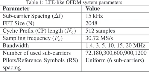
ser-Table 1: LTE-like OFDM system parameters
Parameter Value
Sub-carrier Spacing (∆f) 15 kHz
FFT Size (N) 2048
Cyclic Prefix (CP) length (Ng) 512 samples Sampling frequency (Fs) 30.72 MS/s
Bandwidth 1.4, 3, 5, 10, 15, 20 MHz Number of used sub-carriers 72,180,300,600,900,1200 Pilots/Reference Symbols (RS)
spacing
Uniform (6 sub-carriers)
vices, and lower support costs. Fig. 14 shows the example ar-chitecture for C-RAN prototyping using CROWD testbed.
USRP-RIO USRP-RIO
CROWD Local Controller (CLC)
LTE eNB
RRH/L1 USRP-RIO
LTE eNB RRH/L1
USRP-RIO LTE UE LTE UE
USRP-RIO USRP-RIO
LTE UE LTE UE
Virtual BS Pool (L1/L2/L3) (Runs on PXIe Platform
USRP-RIO USRP-RIO
LTE eNB RRH/L1
LTE UE USRP-RIO
LTE UE (Runs on
(Runs on PXIe PlatformPXIe Controller CPRI/10gE Interface
Figure 14: Cloud RAN (C-RAN) Prototyping
6 RESULTS
In this section, we describe the initial results from our testbed highlighting the physical layer performance and also highlight the feasibility of our experiments in an indoor setting. The cur-rent PHY implementation has only one antenna port (i.e., SISO) supported per node with FDD operation. We have chosen to im-plement only the downlink transmitter/receiver and we plan to show the performance of our algorithms in downlink direction. The PHY modules have been designed to loosely follow 3GPP specifications, and hence referred to as “LTE-like” system, since our testbed is intended for research instead of commercial devel-opment. We describe main LTE OFDMA downlink system pa-rameters in Table 1. However, some components and procedures of a commercial LTE transceiver (for example, random access and broadcast channel) have deliberately been omitted because they fall outside the scope and requirements of our testbed. Only essential data and control channel functions are implemented.
6.1 Downlink RF Characterization
il-lustrates the required SNR for achieving the pre-defined BLERs for all MCSs. Although the desired BLER before HARQ is 0.1 in LTE, we opt to show the results BLERs of 0.01 and 0.0001. Currently, we aim for BLER of 0.0001 because our current im-plementation does not support HARQ. As observed in the figure, the required SNR for a given BLER increases as we use higher MCSs. Because higher MCSs carry more data and have lower coding rate, they are more susceptible to errors, hence, they de-sired higher SNR. The high variations after MCSs 9 and 16 are due to change of Modulation schemes. Finally, lower BLERs re-quire higher SNR in order to better harness the impact of channel impairments.
-2 0 2 4 6 8 10 12 14 16 18 20
0 1 2 3 4 5 6 7 8 9 10 11 12 13 14 15 16 17 18 19 20 21 22
SN
R
[
d
B]
MCS index
QPSK 16QAM 64QAM
BLER=0.0001 BLER=0.01 BLER=0.1
Figure 15: MCS-SNR mapping for BLERs of 0.1, 0.01, and 0.0001.
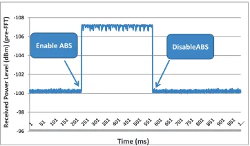
6.2 Almost Blank Subframe (ABS) PHY Calibration
ABS algorithm implies the muting of data sub carriers when there is no MAC PDU from higher layers. However, we still need to transmit DL Reference Symbols (RS), PSS, SSS, PD-CCH to keep physical layer synchronization. In figures below, we illustrate the power level reduction on an average of sub-frame with/without ABS activation. Fig. 16 shows the signal magnitude comparison at the output of FFT for data and pilot subcarriers. We can see from the results of Fig. 16 that after enabling ABS, there is considerable reduction of signal mag-nitude of data sub-carriers, whereas pilot sub-carriers are not affected due to application of ABS. Fig. 17 shows the reduction in average power at the input of FFT. We see from the results of Fig. 17 that there is about 7 dB reduction in the average re-ceived signal power at the input of FFT at the receiver. Since, there ABS results in the suppression of only data carriers and not pilot carriers. This results in ideal average power reduction of 10log(6)=7.8 dB (as there is one pilot sub-carrier for every 5 data sub-carriers) in each symbol. In these calculations, we do not take into account the fact that PSS, SSS, PDCCH are still transmitted during ABS frame. Hence, the results of these two figures only correspond to symbols that carry only PDSCH channel. These preliminary results only indicate the receiver characteristics when ABS is applied, however in future we plan to conduct more extensive experiments in an indoor setting on the effect of enabling ABS in a multi-cell environment.
0 0.2 0.4 0.6 0.8 1 1.2
Average Signal magnitude - Data Resource Elements (one OFDM Symbol)
Average Signal magnitude - Pilot Resource Elements (one OFDM Symbol)
A
v
e
ra
g
e
S
ig
n
a
l
Ma
g
n
it
u
d
e
(p
o
st
FFT
)
Time (ms)
Disable ABS Enable ABS
Figure 16: Post FFT Signal Magnitude Comparison (before/after ap-plying ABS)
-108
-106
-104
-102
-100
-98
-96
Re
ce
iv
e
d
P
o
w
e
r
Le
v
e
l
(d
B
m
)
(p
re
-FFT
)
Time (ms)
DisableABS Enable ABS
Figure 17: Average Received Signal Power (pre-FFT) (before/after ap-plying ABS)
7 CONCLUSION
ACKNOWLEDGMENT
The research leading to these results has received funding from the European Union Seventh Framework Programme (FP7/2007-2013) under grant agreement no. 318115 (Connec-tivity management for eneRgy Optimised Wireless Dense net-works - CROWD).
REFERENCES
[1] H. Ali-Ahmad, C. Cicconetti, A. de le Oliva, V. Mancuso, , M. R. Sama, P. Seite, and S. Shanmugalingam., “SDN-based Network Architecture for Extremely Dense Wireless Networks,” IEEE Software Defined Networks for Future Networks and Ser-vices (IEEE SDN4FNS), November 2013.
[2] A. Gudipati, D. Perry, L. E. Li, and S. Katti, “SoftRAN: Software
Defined Radio Access Network,” inACM HotSDN, 2013.
[3] “OpenFlow Specifications.” [Online]. Available:
https://www.opennetworking.org/sdn-resources/onf-specifications/openflow
[4] “GnuRadio Project.” [Online]. Available: http://gnuradio.org/
[5] “BEECube.” [Online]. Available: http://beecube.com/
[6] “Nutaq.” [Online]. Available: http://nutaq.com/en
[7] “Microsoft Research Software Radio (Sora).” [Online]. Available: http://research.microsoft.com/en-us/projects/sora/
[8] “NI PXI Platform.” [Online]. Available: http://www.ni.com/pxi/
[9] “NI USRP RIO Platform.” [Online]. Available:
http://sine.ni.com/nips/cds/view/p/lang/en/nid/212174
[10] “OpenAirInterface.” [Online]. Available:
http://www.openairinterface.org/
[11] “Amarisoft Corp.” [Online]. Available:
http://www.amarisoft.com/
[12] R. Gupta, T. Vogel, N. Kundargi, A. Ekbal, A. Morelli, V. Man-cuso, V. Sciancalepore, R. Ford, and S. Rangan, “LabVIEW based Platform for prototyping dense LTE Networks in CROWD Project,” inEuCNC, 2014.
[13] “Overview of NS3 based LTE LENA Simulator.” [Online].
Available:
http://networks.cttc.es/mobile-networks/software-tools/lena/
[14] V. Sciancalepore, V. Mancuso, A. Banchs, S. Zaks, and A. Capone, “Interference Coordination Strategies for Content
Up-date Dissemination in LTE-A,” inThe 33rd Annual IEEE
Interna-tional Conference on Computer Communications (INFOCOM),
2014.
[15] “LTE eNB L1 API Definition, October 2010, Small Cell Forum.”
[Online]. Available:
http://www.smallcellforum.org/resources-technical-papers
[16] L. Lindbom, R. Love, S. Krishnamurthy, C. Yao, N. Miki, and V. Chandrasekhar, “Enhanced inter-cell interference
co-ordination for heterogeneous networks in lte-advanced: A
survey,” CoRR, vol. abs/1112.1344, 2011. [Online]. Available:
http://arxiv.org/abs/1112.1344
[17] “NI-TimeSync Module .” [Online]. Available:
http://www.ni.com/white-paper/11466/en/
[18] “IEEE 1588 PtP Protocol .” [Online]. Available:
http://www.nist.gov/el/isd/ieee/ieee1588.cfm
[19] 3GPP, “Evolved Universal Terrestrial Radio Access Network (E-UTRAN); X2 application protocol (X2AP), 3rd ed,” 3GPP, tech-nical Specification Group Radio Access Network, Tech. Rep.
[20] “3GPP LTE-Unlicensed Study.” [Online].
Avail-able:
http://www.3gpp.org/news-events/3gpp-news/1603-lte_in_unlicensed
[21] “Qualcom LTE-U Whitepaper.” [Online].
Avail-able: https://www.qualcomm.com/media/documents/files/white-paper-extending-lte-advanced-to-unlicensed-spectrum.pdf
[22] S. Chiou, L. J. C. Jr., and C.-C. Shen,
“Sur-vey of LTE and WiFi Co-existence in Unlicensed
Band.” [Online]. Available: http://www.eecis.udel.edu/
ci-mini/memo/20140930_Steve_report.pdf
[23] A. M. Cavalcante, E. Almeida, R. Vieira, F. S. Chaves, F. M. Abi-nader, S. Choudhury, E. Tuomaala, and K. Doppler, “Performance evaluation of lte and wi-fi coexistence in unlicensed bands,” in IEEE Vehicular Technology, Spring 2013, 05/2013 2013.
[24] Qualcomm LTE-Direct Whitepaper, “Creating the
dig-ital 6th Sense with LTE Direct.” [Online]. Available:
https://www.qualcomm.com/media/documents/files/creating-a-digital-6th-sense-with-lte-direct.pdf
[25] China Mobile C-RAN Whitepaper, “C-RAN: The
Road Towards Green RAN.” [Online].