The development of strategies for working with
three-dimensional glass forms using two-three-dimensional waterjet
cutting
Shelley Doolan
Swansea Metropolitan University, School of Glass
Abstract
This enquiry will suggest ways in which the scope of the artist may be expanded by the use of CAD/CAM technology, with a focus on waterjet cutting. Consideration will be given to strategies for processing three-dimensional models for the most commonly available two-dimensional water jet cutting process.
1. INTRODUCTION
Anecdotally, artists talk of barriers to technology, such as cost; lack of familiarity, knowledge and skills; a squeamishness associated with computers; incomprehension of ‘jargon’; and a discomfort within an engineering environment.
Despite these misgivings, there is a nascent awareness amongst artists and craftspeople of the potential offered by technology. The work of practitioners such as Michael Eden(1) and Geoffrey Mann(2) for example, has been widely exhibited and contributed to a greater interest in rapid prototyping processes by craftspeople.
An early-adopter of waterjet cutting technology was Robert Knottenbelt, who made use of the process in his glass practice from 1986 onwards(3). More recently the work of Vanessa Cutler(4) has brought the use of waterjet cutting to a contemporary audience within the glass-art scene.
The scope of the enquiry will be limited to a 2-axis waterjet cutting machine, that technology being the most commonly-available both within university departments and via industry subcontractors.
It will therefore be necessary to assess the design strategies required to create three-dimensional objects using a two-three-dimensional cutting process. As well as glass cutting, the paper will address – through case-studies – less direct methods to include the cutting of moulds and formers as well as wax models for subsequent processing by lost-wax casting. The paper will illustrate how the use of technology can segue seamlessly with the hand-made through the documentation of the design and production of glass artefacts.
2. DESIGN STRATEGIES – CASE STUDIES
2.1 Cutting and assembly
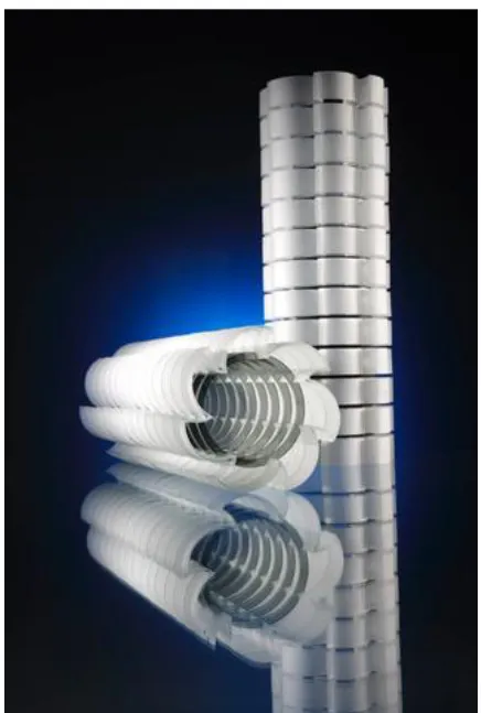
One approach employed by Vanessa Cutler is to cut two-dimensional profiles from15mm thick float glass and assemble and bond to create stacked towers.
This approach makes a fairly pure use of the technology and is suggestive of the artist’s acceptance of the influence of process upon design. As Cutler comments “...the generation of ideas comes about from the influence of the process... it suggested the shapes and forms that could be translated from paper into glass” (4).
Figure 2. ‘007’ by Margareth Trolli
2.2 Contouring
Contouring or sectioning is a useful strategy for processing a three-dimensional CAD model for production by two-dimensional cutting.
Contouring is an approach to construction with links to architecture, aircraft and boat-building. As such it is a function embedded within most CAD software.
As a starting point, the researcher used an existing model which had been milled to produce a former for a kiln-cast glass panel illustrated below.
Figure 3. ‘Iteration 135’ by Shelley Doolan
The three-dimensional computer model was then processed using a simple contour function, with the interval set at 4mm (being the thickness of glass used).
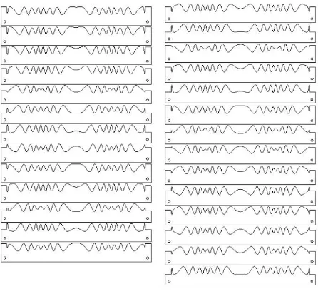
The contour profiles are then laid out and nested for waterjet cutting in glass.
Figure 5. Layout of contour sections for waterjet cutting
The glass was cut using 120mesh garnet abrasive, with a lead-in from the edge, enabling high pressure of 5500psi to be used. An abrasive flow rate of 225g/minute was used, with a traverse rate of 1000mm/minute.
After cutting, the glass profiles can be edge polished and assembled.
Figure 6. Waterjet cut and assembled glass profiles
2.3 Intersecting waffles
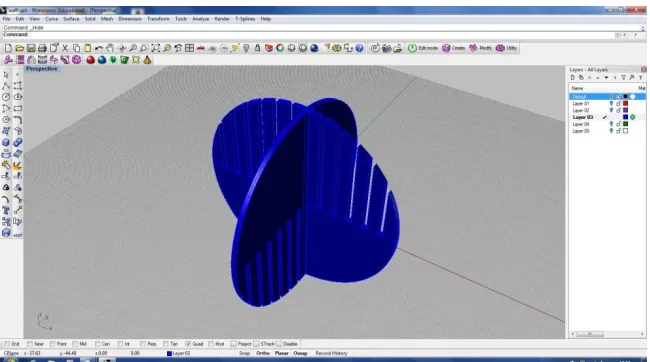
A design strategy which lends itself to two-dimensional cutting is the creation of intersecting, interlocking waffles taken from a three-dimensional object.
Using a script within three-dimensional modelling software, a base geometry is sectioned to enable the creation of ‘waffle’-type intersecting profiles.
Figure 7. Sectioning of base geometry
The profilesare processed for 2D cutting
Figure 9. 2D profiles
Once cut, the glass can be assembled and UV bonded.
2.4 Manual waterjet ‘carving’
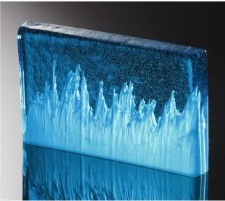
The researcher has experimented with a process of carving into pre-cast blocks of glass to create internal cavities and sculpting. In this instance, the waterjet machine was operated manually, without programming, with the researcher adjusting the speed control during the pass of the abrasive jet to create variances in the depth of jet penetration of the glass block.
Three lines were cut into the block with a gradation in overall depth to create a layering effect.
Figure 11. ‘Vertiginous’ by S Doolan
2.5 Unrolling developable surfaces
One approach to fabricate forms too large to be practicably or economically prototyped or milled, is – where possible – to unroll the developable surfaces.
Figure 12. 3D model and unrolled surfaces
Once unrolled, the profile can be cut to provide a former for the model. In this case, thin gauge aluminium was cut, folded, rolled and secured to a base board to allow molten wax to be poured in to create a
wax replica of the original model for subsequent lost
wax casting. All
subsequent processes
reverted to traditional craft techniques. The finished glass pieces were 75cm x 55cm x 38cm.
2.6 Cutting the mould and negative space
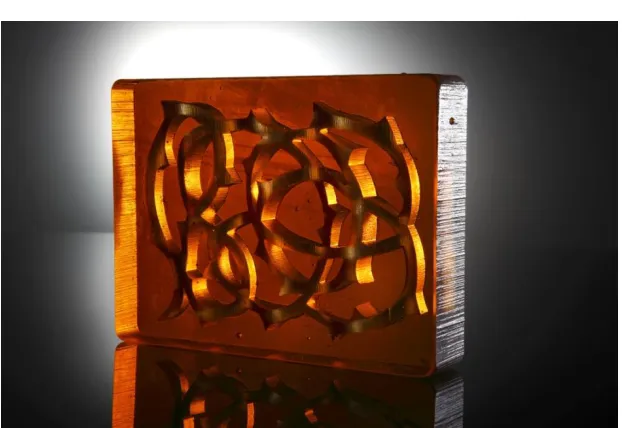
Figure 14. ‘Brambles’ blocks by S Doolan
After initial trials, the researcher decided to use the waterjet machine to create the mould and components to cast glass blocks with relief detail – in this case a bramble motif.
Refractory plaster blocks were cast and waterjet cut. The initial profile being a sinusoidal wave, cut along one plane of the block. The block was then rotated and cut from a different plane to create a plaster positive of the bramble. When cast in glass, this would form the negative space within the block of glass.
Figure 15. Cutting of the bramble motif
`
Figure 16. Moulds in preparation for kiln-firing
This was a useful and effective way to prototype designs. The use of the waterjet enabled the crisp and precise cutting of the plaster motif.
2.7 Cutting for lost-wax
The researcher wished to introduce a greater degree of three-dimensionality to work produced. To this end a number of test cuts were carried out on plaster (as mentioned above) and also on wax.
The tests proved promising. The cut edge of the wax showed minimal signs of jet-lag or taper.
Another advantage was that wax blocks up to 165mm height could be cut (the maximum clearance under the jet), and that a ‘reasonable’ cutting speed could be used.
A typical traverse rate of 70–
250mm/minute (depending on the
thickness of the material), and a stand-off distance of 2mm was used
The object was designed with a curved front face. It was decided to experiment with first cutting this profile in the top plane of the block of wax before rotating to cut the pattern from the front plane.
Figure 18. Initial phase of cutting profile and re-assembling
The maximum clearance under the cutting head was 165mm. This also proved to be reaching the limits of depth of cut whilst retaining an acceptable surface at acceptable traverse rates. Therefore the block was cut into four sections and the same curved profile cut from each. The blocks were then reassembled prior to being rotated and cut from the front face.
The cut wax pieces were then joined and refined by hand before being invested in refractory plaster for subsequent lost-wax casting.
Figure 20. Assembled wax model, invested in plaster mould
The technique was subsequently made more efficient by the pre-casting of the wax into a former to create the curved front face. This necessitated cutting from one plane only and obviated the need for time-consuming re-assembly.
The researcher has used the technique of waterjet cutting wax for further pieces. It has proved to be an effective way of working, enabling the neat and precise cutting of forms from CAD data. The process allows for objects to be created with a depth currently of 165mm. Further work is planned to see whether this can be increased with satisfactory results by submerging wax blocks into the tank.
Figure 21. ‘Propagate’ by S Doolan
3. CONCLUSION
REFERENCES
(1) Eden, M., 2010. A New Eden. In: Crafts Magazine. Vol. 222. London: Crafts Council. pp. 40-45.
(2) Mann, G., 2011. Studio Mr Mann. [Online]. Available at: www.mrmann.co.uk/long-exposure-series-flight-takeoff.
(3) Ioannou, Noris Dr., 2006. A Vanishing in the Peripheral Eye – the Evolving Glass Art of Rob Knottenbelt. In: Craft Arts International, Issue # 65. Neutral Bay, NSW: Craft Arts International pty. pp 24-29.
(4) Cutler. V., 2006. Investigation of cutting creatively glass with abrasive waterjet for the glass artist’s studio. PhD Thesis, University of Sunderland
FIGURES
1. ‘Transformers’ by Vanessa Cutler. Photo: Simon Bruntnell 2. ‘007’ by Margareth Trolli. Photo: Simon Bruntnell 3. ‘Iteration 135’ by Shelley Doolan. Photo: Simon Bruntnell
4. Contouring of model. Image: Author
5. Layout of contour sections for waterjet cutting. Image: Author 6. Waterjet cut and assembled glass profiles. Photo: Author
7. Sectioning of base geometry. Image: Author
8. Interlocking profiles. Image: Author
9. 2D profiles. Image: Author
10. Assembled glass sphere. Photo: Author
11. ‘Vertiginous’ by S Doolan. Photo: Simon Bruntnell 12. 3D model and unrolled developable surfaces. Photo: Author 13. Cast glass. Photo: Author
14. ‘Brambles’ block, by S Doolan. Photo: Simon Bruntnell 15. Cutting of brambles motif. Photo: Author
16. Moulds in preparation for kiln-firing. Photo: Author 17. ‘Scale’ by S Doolan. Photo: Simon Bruntnell
18. Initial phase of cutting profile and re-assembling. Photo: Author 19. Cutting of pattern on front face. Photo: Author