IJEDR1702067
International Journal of Engineering Development and Research (www.ijedr.org)388
ANALYSIS AND DESIGN OF DEPLOYABLE
BRIDGE BASED ON ORIGAMI SKILL
(1)
Bapat Himanshu Yogesh,
(2)Dr. Siddharth G. Shah
(1)
Student of ME structural engineering,
(2)Professor & Head
(1)(2)
Civil engineering Department
(1)(2)Marwadi Education Foundation - Faculty of P.G. Studies & Research in Engineering & Technology
Rajkot, Gujarat, India
Abstract— At the time of disasters like earthquake, flood and tsunami the road and bridges are the lifelines for rescue works. If the bri dges are badl y damage d or any of their span has been c ollapse d than the instant re quire ment will be generate d to built the bri dge. This require ment can be fulfilled by mobile bri dge whic h can be tr ans por te d to the site and can fill the gap. In this research we are analyzing the de pl oyable type mobile bri dge which can be fol de d and tr ans por te d anywhere. We designed it for s ingle way two lanes with IRC class A loading. 10m and 15 m span is taken for analysis with di fferent stage of ope ning for self weight and for full live load. All anal ysis has been carrie d out on STAAD PRO software. The bri dge is designed for three different materials which are titanium, steel and aluminum. Different geome tric angle for X me mbers are used to de ter mine most effec ti ve geome try. After anal ysis we can c onclude that the 15m s pan with 45 degree is the most e fficient i n ter ms of deflection and ti tanium alloy is the most ec onomical materi al for the use.
Inde x Ter ms—De pl oyable Bri dge, X me mbers, mobile type , IRC class A loading
INTRODUCTION:-
There are many types of disasters such as Earthquakes; Floods & Tsunamis may generate on earth. The life line structures like road and bridges must survive through the disasters. Bridge and culverts may get damaged and cannot be repair and rebuilt instantly and due to this the affected area becomes isolated. So to overcome this deployable type bridge can be used. This type of bridges can be loaded on truck with different type of spans and can be transported anywhere. There are many type of geometry possible but for longer and heavy duty span the scissor type X elements are generally used. These elements also provided with diffe rent geometric angles. Analysis is carried out for span 10m and 15m. Th is scissor type bridge provides several advantages (1) fewer me mbe rs used for construction so deployment and storage will be quick. (2) Transportation and assembling and disassembling will be easy. (3) Deploy ment performance will be higher because this type deploy and store by control forces. Material p lay an important role in any structure here we taken three materials for bridge which are a lu minum t itaniu m and steel. Here are through this research we are determin ing the most economica l materia l, appropriate sizes of me mbers and most effective angle of X me mbers for diffe rent span by structural design. Following figure 1 and figure 2 e xp la ins about this kind of mo bile bridge can be transported and erected at the any location by deploying it and after use again we can fo lded it.
PAST RES EARHCH WORK:-
[1]
Rahula and Kaushik Ku marb have done research on design and optimization of portable foot bridge in 2013. In this paper the author develops the portable foot bridge using ANSYS with different types of materia l such as structural steel, titaniu m alloy and alu minu m alloy with different cross section. The design is carried out for Foot Bridge only with span of 1.5mt and width of 0.5m. The loading given is of 1000kg and check for deflection was carried out for different spans . [2]Ichiro Ario , Masatoshi Naka za wa , Yoshikazu Tanaka , Izu mi Tan ikura and Syuichi Ono have done research on Design and Optimizat ion of Portable Foot Bridge in 2013. In this paper the author expla ins about beam model with the cla mped supports. The concept of foldable structure of origami
IJEDR1702067
International Journal of Engineering Development and Research (www.ijedr.org)389
Deflection of prototype and model was checked. [3]Authors J. Aversenga and J. F. Dubéa have worked on Des ign, ana lysis and self stress setting of a lightweight deployable tensegrity modular structure in 2012. In this paper they have shown Tensegrity systems, made of struts and cables in a self stress state, lightweight, visually transparent and deployable. They have considered a beam connected with 4 bars, 12 cables in 2 horizontal and diagonal element in upper and lower nodes for geometry h = 1.30 m, b = 80 c m, L = 12 m. setting of geometry is carried out deployment and active cable setting. The proposed solution for supporting a 12 m footbridge on a width of 1 m is a tensegrity beam weighting 440 kg. This is a linear weight of 37 kg/ m. The author concluded that the system can be transported and deployed easily. [4]Author D.M. Jade and G.R. Patil had worked on light weight scissor deployable structure in 2015. They used scissor me mbers with different span and for different angles of 30°, 45° and 60°. They used [5]STAAD PRO software fo r analysis and design and used Indian standard angle sections for design.MET HODOLOGY:-
Here we have performed analysis for 10m and 15m span of bridge. At the time of deployment our bridge will be in cantilever stage until it riche to other end. So analysis is also done for different deployment stage of ¼ cantilever span, ½ cantilever span, ¾ cantilever span, full cantilever span and for simply supported with [6]IRC c lass A loading as shown in figure 3. Than they are also design for modified geometry of 30°, 45° and 60° angles of X me mbers. In ne xt stage they are checked for different materia l properties of me mbe rs made up of steel, Alu minum alloy and of titaniu m. Their design is performed in STAAD PRO with [ 7]IS 800.
MODELING:-
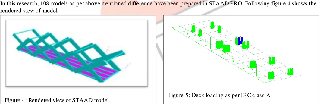
In this research, 108 models as per above mentioned diffe rence have been prepared in STAAD PRO. Following figure 4 shows the rendered view of model.
Deck load as per IRC class A has been generated in software by bridge deck progra m. Figure 5 shows the deck loading as per IRC class A. Width of bridge is kept 3.8m and height of bridge is kept 4.1m. Steel plate of 15mm th ickness is provided as deck. Under the deck the grid of rectangular hollow sections are provided to transfer the bridge deck live load to supportive pin me mbers. These pin me mbers are made up of solid materia l because they performed two task in structure, first they support deck plates and me mbe rs and second they act as pin on which X me mbers can rotate and bridge can be closed and open. These membe rs are also provided at top for connection and bracing purpose as shown in figure 4. Two types of supports are provided in bridge, the fixe support at bottom wh ich acts as main anchor support for bridge and above that sliding support provided which hold the upper limb of scissor X me mbe rs. Following loads and load combinations have been taken as per [8]IS 875 part 5.
Figure 4: Rendered view of STAAD model. Figure 5: Deck loading as per IRC c lass A
Figure 3: Different geo metric angles with diffe rent stage of opening for 10m and 15m span
1. DL (dead load) includes self weight of structural me mbe rs 6. 1.5(DL + IRC )
IJEDR1702067
International Journal of Engineering Development and Research (www.ijedr.org)390
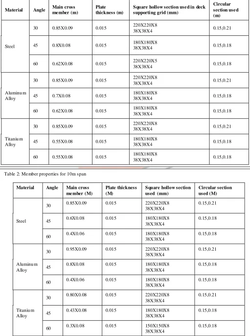
Following table show the me mber sizes and standard sections used in structure. Table 1 indicates me mber data of 10m span and table 2 indicates me mbe r data of 15m span.Table 1: Me mber propert ies for 15m span
Material Angle Main cross me mber (m)
Plate
thickness (m)
Square hollow section use d in deck supporti ng grid (mm)
Circular section use d (m)
Steel
30 0.85X0.09 0.015 220X220X8
38X38X4 0.15,0.21
45 0.8X0.08 0.015 180X180X8
38X38X4 0.15,0.18
60 0.62X0.08 0.015 220X220X5
38X38X4 0.15,0.18
Aluminu m Alloy
30 0.85X0.09 0.015 220X220X8
38X38X4 0.15,0.21
45 0.7X0.08 0.015 180X180X8
38X38X4 0.15,0.18
60 0.62X0.08 0.015 180X180X8
38X38X4 0.15,0.18
Titaniu m Alloy
30 0.85X0.09 0.015 220X220X8
38X38X4 0.15,0.21
45 0.55X0.08 0.015 180X180X8
38X38X4 0.15,0.18
60 0.55X0.08 0.015 180X180X8
38X38X4 0.15,0.18
Table 2: Me mber properties for 10m span
Material Angle Main cross me mber (M)
Plate thickness (M)
Square hollow section used (mm)
Circular section used (M)
Steel
30 0.85X0.09 0.015 220X220X8
38X38X4
0.15,0.21
45 0.6X0.08 0.015 180X180X8
38X38X4
0.15,0.18
60 0.4X0.06 0.015 180X180X8
38X38X4
0.15,0.18
Aluminu m Alloy
30 0.95X0.09 0.015 220X220X8
38X38X4
0.15,0.21
45 0.8X0.08 0.015 180X180X8
38X38X4
0.15,0.18
60 0.4X0.06 0.015 180X180X8
38X38X4
0.15,0.18
Titaniu m Alloy
30 0.80X0.08 0.015 220X220X8
38X38X4
0.15,0.21
45 0.43X0.08 0.015 180X180X8 38X38X4 0.15,0.18
60 0.3X0.08 0.015 150X150X8
38X38X4
IJEDR1702067
International Journal of Engineering Development and Research (www.ijedr.org)391
RES ULTS:-In Analysis of bridge models in STAAD PRO, observations of deflection of span in diffe rent loading condition and for diffe ren t degree of scissor me mbe rs are tabulated below.
Table 3: 30° (10m) span deflection co mparison
Span
Simply
Suppor te d (IRC)
Simply
Suppor te d Full cantile ver ¾ cantile ver ½ cantile ver ¼ cantile ver
Steel 30.944 4.716 13.033 9.482 3.99 1.066
Aluminu m Alloy 75.31 4.655 11.338 7.73 3.175 0.859
Titaniu m A lloy 48.519 4.695 13.859 10.825 4.58 1.213
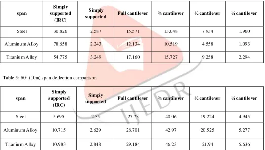
Table 4: 45° (10m) span deflection co mparison
span
Simply supporte d
(IRC)
Simply
supporte d Full cantile ver ¾ cantile ver ½ cantile ver ¼ cantile ver
Steel 30.826 2.587 15.571 13.048 7.934 1.960
Aluminu m Alloy 78.658 2.243 12.134 10.519 4.558 1.093
Titaniu m A lloy 54.775 3.249 17.160 15.727 9.258 2.294
Table 5: 60° (10m) span deflection co mparison
span
Simply supporte d
(IRC)
Simply
supporte d Full cantile ver ¾ cantile ver ½ cantile ver ¼ cantile ver
Steel 5.695 2.35 27.73 40.06 19.224 4.945
Aluminu m Alloy 10.715 2.629 28.701 42.97 20.525 5.277
Titaniu m A lloy 10.983 2.848 29.184 46.23 21.94 5.636
Table 6: 30° (15m) span deflection co mparison
span
Simply supporte d
(IRC)
Simply
supporte d Full cantile ver ¾ cantile ver ½ cantile ver ¼ cantile ver
Steel 53.427 6.83 17.23 13.141 5.88 1.56
Aluminu m Alloy 94.316 6.498 17.198 13.311 6.224 1.62
IJEDR1702067
International Journal of Engineering Development and Research (www.ijedr.org)392
Table 7: 45° (15m) span deflection co mparisonspan
Simply supporte d
(IRC)
Simply
supporte d Full cantile ver ¾ cantile ver ½ cantile ver ¼ cantile ver
Steel 21.044 2.972 26.346 20.136 13.277 3.278
Aluminu m Alloy 57.127 3.002 40.185 34.938 17.321 4.22
Titaniu m A lloy 40.779 3.913 48.154 45.7 28.22 6.81
Table 8: 60° (15m) span deflection co mparison
span
Simply supporte d
(IRC)
Simply
supporte d Full cantile ver ¾ cantile ver ½ cantile ver ¼ cantile ver
Steel 15.481 2.49 33.175 78.141 53.751 6.151
Aluminu m Alloy 42.129 2.837 44.032 95.93 69.341 7.433
Titaniu m A lloy 28.071 3.05 46.217 96.56 75.853 8.661
CONCLUSS ION:-
We concluded following points from above mentioned results
1) Fro m the above mentioned results in table 9 and in table 10, titaniu m alloy a mong those three materials is the least consume materia l because it shows properties of high strength & light weight for 45° angle in 10m as well as in 15m span.
2) As the angle of scissor me mber increases, the dead weight of structure is also increased. Due to this the self we ight of structure will a lso increase which results in higher deflection. We can observe this conclusion in above tables.
3) For simply supported span with IRC loading, as the angle of scissor me mber increases the amount of deflection will reduce.
4) By observing me mbe r sizes fro m table 1 and 2 we can conclude that as the me mber angle decreases the sizes of me mbe rs are also reduced.
Table 10: (10m) span total quantity consumption
Material Angle Quantity of material consume d
Steel 30° (5.40m3) 42446Kg
45° (4.28m3) 33640Kg
60° (3.39m3) 26642Kg
Aluminu m
Alloy
30° (5.87m3) 15620Kg
45° (5.34m3) 14218Kg
60° (3.22m3) 8568Kg
Titaniu m
Alloy
30° (4.76m3) 21073Kg
45° (3.015m3) 13347 Kg
60° (3.04m3) 13475Kg
Table 9: (15m) span total quantity consumption
Material Angle Quantity of
material c onsume d
Steel 30° (6.77m3) 53198Kg
45° (7.81m3) 61340Kg
60° (8.05m3) 63269Kg
Aluminu m
Alloy
30° (6.78m3) 18045Kg
45° (7.07m3) 18817Kg
60° (7.86m3) 20912Kg
Titaniu m
Alloy
30° (6.77m3) 53198Kg
45° (5.96m3) 26398Kg
IJEDR1702067
International Journal of Engineering Development and Research (www.ijedr.org)393
REFERENCES:-[1] Rahula, Kaushik Ku marb., “ Design and Optimization of Portable Foot Bridge”, PROCEDIA ENGINEERING.(ELSEVI ER) Vo lu me 4, Procedia Engineering 97 (2014) 1041-1048.
[2] Ichiro Ario , Masatoshi Naka zawa , Yoshika zu Tanaka , Izu mi Tan ikura , Syuich i Ono., “Develop ment of a prototype deployable bridge based on origami skill” ., Automation in Construction.(ELSEVIER), Automation in Construction 32 (2013) 104-111.
[3] J. Aversenga and J. F. Dubéa., “Design, analysis and self stress setting of a lightweight deployable tensegrity modular structure”., Science direct. (ELSEVIER), Procedia Engineering 40 (2012) 14-19
[4] D.M Jade and G.R.Patil, “light weight scissor deployable structures”, March 2015, volu me 3, IJETMS.
[5] STAAD PRO SS6 software for structural analysis and design by Bentley Inc.
[6] IRC-5-1998- code of practice for road bridges
[7] IS 800 : 2007 Code of p ractice fo r structural steel design published by Bureau of India Standards