IJEDR1803081
International Journal of Engineering Development and Research (
www.ijedr.org
)
481
Variation in Properties due to Speed in Cold Wire
Drawing
1Prakash Gawali, 2DR. S.C.Sharma, 3Ashish Khare 1Assistant Professor, 2Professor, 3Assistant Professor
Mechanical Engg. Deptt. Acropolis Institute of Technology & Reserch(M.P)
Abstract- The speed in cold wire drawing process become very common, because of increase in customer demands and production rate and it is vary essential to the effect of speed on the properties of the drawn wire. In this work the effect of high speed drawing (10m/s &30m/s) on mechanical and technological properties of high carbon steel wire has been investigated. Wire rod 5.50mm from steel grade 0.51% carbon and 0.65% carbon were drawn to 1.35mm in 13 draws and two speeds 10m/sec and 30m/sec. After each draw the following properties were determined; tensile strength (Ts), temperature (T), number of twists (Nt), number of bends (Nb). A large drop in the number of has been observed for final
wires because of increased draw speed. However, there is also an advantage as the wire surface is much smoother after drawing at high speed than at low speed. The results were practically and statistically estimated.
Keywords-, temperature, tensile strength, speed. Wire drawing
_____________________________________________________________________________________________________
INTRODUCTION
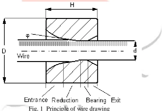
In the wire drawing process, the cross section is reduced by the pulling it through a tungsten carbide die which is inserted in the die box and the wire is pulled by cylindrical drum which is run by electric motor [1].
Fig. 1 Principle of wire drawing
The major variables in the drawing process are reduction in cross sectional area, die angle, friction along the die work piece interfaces and drawing speed[10]. For successful drawing operation, careful selection of the process parameters should be carried out. The drawing speed depends on wire material as well as reduction in area for high drawing speeds[2], the heat generated does not have sufficient time to dissipate and a substantial rise in the temperature [3, 4] occurs which has detrimental effect on the quality of product.
Heat generation in wire drawing was first addressed by Siebel and Kobitzsch. [6]. An early refinement of this analysis was made by Korst.[7]. The approach is still widely used today in estimating the temperature rise in wire drawing. While the model predicts that the maximum temperature rise in wire varies with the square root of the drawing speed. It has been observed in experiments to vary linearly with the drawing speed[5]. As well as the cube root of the speed [8]. More recently, this temperature rise was observed to be independent of drawing speed.[9]
Wire drawing operations employing high area reduction and improved lubrication and friction conditions not only save energy, but also reduce production cost by avoiding intermediate passes and annealing operations [5].
IJEDR1803081
International Journal of Engineering Development and Research (
www.ijedr.org
)
482
Experimental procedureThe material used to the investigation was rise rod about diameter 5.50mm of low carbon steel after TRIP type heat treatment. The chemical composition of used steel in the investigation is presented in table 1.
TABLE 1
The chemical composition of TRIP steel Mass contents in %
C Mn Si P S Cu Ni Mo Sn
0.51 1.25 0.70 0.01 0.07 0.022 0.01 0.005 0.004
0.65 1.22 0.60 0.015 0.08 0.021 0.01 0.005 0.004
TABLE 2
The volumetric phase contain Phase contain
Ferrte, % Bainite, % Retained austenite
+~Martensite 1, %
Retained austenit2
%
70.3 16.8 8.6 6.8
After heat treatment and metallographic investigation which confirmed used TRIP type structure, TRIP steel wires drawn in 13 drafts with different drawing speed from diameter 5.5mm to 1.35mm by using classical die with sintered carbides about angle 2α =120. In table 3, the main parameters of drawing process are shown, where: V – drawing speed, A – medium single draft, A
t
– total draft in percentage.
TABLE 3
The parameters of drawing process Variant Drawing
machine
Carbon % V , m/s Drafts number
A% At%
A BB-8 C – 51 8 13 20 93.98
B BB-8 C- 51 25 13 20 93.98
A BB-8 C – 65 8 13 20 93.98
B BB-8 C – 65 25 13 20 93.98
In order to estimate the influence of drawing speed on mechanical properties of wires with TRIP effect, described relation between tensile strength Ts, Temperature T in 0c uniform elongation in total draft function for wires drawn according to variant
A (V= 8 m/s), B(V = 25m/s).
For better estimation of the influence of drawing speed on properties TRIP steel wires in the work, modeling of wire drawing process (in Drawing 2D program) has been carried out. It has been estimated: temperatures, non-dilatation strain and internal stresses drawn wires. Used in program model multi passes drawing (with a few following after themselves single draft) allows to dissolve coastal task with the range of theory of temperature and tensile strength by the variation of the carbon and speed
Table 4
Schedule of draws and mean values of mechanical and technological properties of wires of steel C51. Draw speed 30m/s. and 10m/s.
V= 30m/s C 51
LP φ AP At Ts T El Ct Nb Nt
(mm) (%) (%) (MPa) 0C (%) (%)
1. 5.50 0.0 - 793 - 8.7 43 14 13
2. 4.91 20 20 872 99 2.6 21 13 14 3. 1.80 20 89.29 1626 239 1.8 53.4 13 28 4. 1.63 20 91.22 1705 250 1..4 52.6 11 30 5. 1.49 20 92.68 1783 261 1.6 51 11 32 6. 1.35 20 93.98 1852 274 1.7 48 10 34
V= 10m/s C 51
1. 5.50 0.0 - 793 - 8 44 14 13
2. 4.91 20 20 867 94 3 48 13 15
IJEDR1803081
International Journal of Engineering Development and Research (
www.ijedr.org
)
483
Schedule of draws and mean values of mechanical and technologicalproperties of wires of steel C71. Draw speed 30m/s. and 10m/s.
V= 30m/s C 65
LP φ AP At Ts T El Ct Nb Nt
(mm) (%) (%) (MPa) 0C (%) (%)
1. 5.50 0.0 - 1038 - 8 46.8 13 12 2. 4.91 20 20 1117 114 2 19.7 12 13 3. 1.80 20 89.29 1871 253 1.8 53.5 12 26 4. 1.63 20 91.22 1950 254 1.5 51.8 11 28 5. 1.49 20 92.68 2018 264 1.6 51.4 10 30 6. 1.35 20 93.98 2097 276 1.7 47.3 9 32
V= 10m/s C 65.
1. 5.50 0.0 - 1038 - 8.7 46.8 13 12 2. 4.91 20 20 1062 108 2.8 50.7 13 14 3. 1.80 20 89.29 1792 221 2.3 53.9 13 30 4. 1.63 20 91.22 1870 238 2.1 53.2 12 32 5. 1.49 20 92.68 1956 242 1.7 50.1 11 34 6. 1.35 20 93.98 1980 256 1.8 48.1 10 36 φ = Wire diameter in mm
Ap= Area reduction per pass in %
At = Total area reduction in %.
Ts = Tensile strength, MPa.
T = Temp. rise in 0C in each pass.
El = Total elongation %.
Ct = Total contraction%
RESEARCH RESULTS: WIRE PROPERTIES
The wire rod were examined at Tata steel plant for the following properties: tensile strength (Ts) in MPa, total elongation
(El) in %, contraction (Ct), number of twists Nt, Number of bends Nb. The mean values in the table were calculated for the
mechanical properties of the 1.35mm wire drawn from the 5.5mm wire rod (steel C 51) at two draw speeds (10m/s and 30m/s). Table 5 shows the same values for the wire drawn from the 5.5mm wire rod (C-65) at draw speeds (10m/s to 30m/s).
The following parameters were calculated for each draw: average temperature on the cross section of the wire (T), wire surface temperature (Tt). Table 4 shows the value of calculated parameters for all draws with a speed 10m/s for steel C51 at a
speed of 30m/s. Table 5 shows the value of A, At, Ts, T, Nb, Nt for all draws for steel C65 at a speed of 10m/s and 30m/s in the
final. The wire surface was observed with an optical microscope at the magnification of 400x.
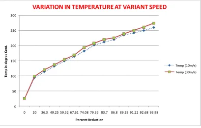
0 50 100 150 200 250 300
0 20 36.3 49.25 59.52 67.61 74.08 79.36 83.7 86.8 89.29 91.22 92.68 93.98
Te
m
p
in
de
gr
e
e
C
e
nt
.
Percent Reduction
VARIATION IN TEMPERATURE AT VARIANT SPEED
IJEDR1803081
International Journal of Engineering Development and Research (
www.ijedr.org
)
484
0 200 400 600 800 1000 1200 1400 1600 1800 2000
0 20 36.3 49.25 59.52 67.61 74.08 79.36 83.7 86.8 89.29 91.22 92.68 93.98
Te
ns
ile
S
tr
e
ng
th
in
M
pa
Percent Reduction in Area
VARIATION OF TENSILE STRESS AT VARIANT SPEED
TS(10M/S) TS(30M/S)
5
15
25
35
45
55
5.
5
4.
91
4.
39
3.
92
3.
5
3.
13
2.
8
2.
5
2.
24
2
1.
8
1.
63
1.
49
1.
35
N
o.
o
f t
w
is
t
Wire Diameter (mm)
Effect of speed on number of twist
C : 51
v = 10m / sec
IJEDR1803081
International Journal of Engineering Development and Research (
www.ijedr.org
)
485
5
10
15
20
25
30
35
40
45
50
5
.5
4
.9
1
4
.3
9
3
.9
2
3
.5
3
.1
3
2
.8
2
.5
2
.2
4
2
1
.8
1
.6
3
1
.4
9
1
.3
5
N
o
. o
f
tw
is
t
Wire Diameter (mm)
Effect of speed on number of twist
C : 65
v = 10m / sec.
v =30m / sec
On the base of a preliminary analysis of data from tables 1-4 and others, it has been decided that process parameters and mechanical properties of tested wires will be estimated for all initial draws, three final draws and last one. This will be helpful in precisely estimating the effect of the draw speed on the above mentioned features of the process and wires ,it can be stated that value of draw stress component in the initial group of draws are independent of a draw speed( for given steel grade). Also that they increase for the final three draws and are highest for the last draw. The calculated values of this draw stress component for test wires made from steel C51 are lower than those made from steel C65. A similar relationship can be seen for the frictional component of draw stress. In general, the contribution of the friction component in a draw stress is smaller than that for a deformation one.
Regarding the effect of draw speed on temperature of a wire surface, Table 4 and 5 shows that it is similar at a slow draw speed, 10m/s, for all three groups of analyzed draws for steel C51. The result, respectively are: draws (1-10) 100 - 1400C, draws
(11-12) 240 - 2500C and for last draw,255- 2600C. Drawing at a speed of 30m/s for this same steel, the comparative surface
temperatures are : draws (1-10) 100 - 2400C,draw (11-12) 260 - 2650C and for last draw 274 - 2760C. Drawing wires made from
the C65 steel resulted in higher surface temperature than for all analyzed wires made from C51 steel, but also in this case for a draw speed of 10m/s the temperature goes on increasing as the carbon percentage increase for draw (1-10) the temperature rise is 10-130c for draw (11-12) temperature rise is 4-80c for last draw the temperature rise is 40c. For a speed of 30m/sec for the
considered group of draw the temperature rise for draw (1-10) is 150c, for draw (11-12) temperature rise is 3-40c, for last draw
temperature rise is 20c.
Regarding the effect of drawing speed on number of bends, Table 4 and Table 5 shows that the number of bends for draw (1-10) having same value, for draw (11-12) the number of bend decrease by 1, for last draw the number of bend decreased by 1.But as the carbon percentage increases from C51 to C65 the number of bends decreased by 1.
Regarding the effect of drawing speed on the torsion value, Table 4 and Table 5 shows that for C46 as the speed varies from 10m/sec to 30m/sec the torsion value for draw (1-5) increases by 1, for draws (6-13) increases by 2.And as the carbon increases from C51 to C65 the torsion value for draw (1-5) decreases by 1, for draw (6-13) decreases by 2.
Drawing speed was found to have a remarkable effect on tensile strength. The tensile strength in MPa initially having lower value but increases constantly from first pass to last pass. For carbon C – 51, from 793MPa to 1820Mpa when the speed is 8m/sec, but tensile strength increases 793 to 1852MPa, when the speed is 25m/sec.
For C – 65 the tensile strength increases from first to last pass 1038MPa to 1870MPa, when speed is 8m/sec and tensile strength increases from 1038MPa to 2097MPa when the speed is 25m/sec.
IJEDR1803081
International Journal of Engineering Development and Research (
www.ijedr.org
)
486
Conclusions1. The increase of speed from 10m/sec to 30m/sec caused the increase of tensile strength about 5-6%. 2. Higher speed decreases the number of twists observed
3. The increase in speed causes to reduce number of bends by 8-10%.and also as the carbon percentage increase the number of bends goes on decreasing.
4. The increase of speed causes rise in temperature, which is required to reduce to avoid strain hardening and wire breakage.
5. At higher speed it is observed that the surface of the wire is smoother than at lower sped.
6. At higher speed the number of bends decreases and it again decreases by increases in the carbon percentage.
References
1. http://en.wikipedia.org/wiki/Wire_drawing
2. A.K.Lis, J. Lis, Effect of hot deformation and cooling rate on phase transformations in low carbon banitic steel, proceeding of 11th international scientific Conference CAM3S’2005 “ Contemporary Achievements in Mechanies, Manufacturing
and Material Science” Gliwice – Zakopane 2005, (CD-ROM).
3. J.W. Pilaczyk, Z.Muskalski, B Golis, S. Wiewiorowska, M. Sliga, Influence of heat treatment of trip steel wire rod on structure and mechanical properties. Conference Proceedings “Global technologies for Emerging Market’s”, New Delhi, India 2006, 171-182.
4. M. Suliga, Z. Muskalski, the influence of single draft on mechanical-technological properties of TRIP steel wires, Metallurgist-news Metallurgist (2007) 353-356.
5. J.Adamezyk., A.Grajcar, heat treatment of TRIP- aided bainitic steel, proceeding of the 11th International scientific
conference CAM3S’2005’ Contemporary Achievements in Mechanics, Manufacturing and Materials Science,Gliwicezakopane2005(CD-ROM).
6. A.K. Lis, B.Gajda, Modeling of the DP and trip microstructure in te CMnAIsi automotive steel, Proceeding of the 11th International scientific conference CAM3S’2005 “Contemporary achievements in mechanics, manufacturing
and the material science”, Gliwice-Zakopane 2005, (CD-ROM).
7 A. Grajcar, Effect of hot working in the γ + α range on a retained austenite fraction in TRIP- aided steel, journal of Achievements in Materials and Manufacturing Engineering 22/2 (2007) 79-82.
8 A. Gajda, A.K. Lis, Thermal processing of CMnAISi steel at (γ+α) temperature range, Journal of Achievements in Materials and Manufacturing Engineering 18(2006) 355-358.
9 P.J. Jacaues, A. Petein, P. Harlet, Improvement of mechanical properties through concurrent deformation and transformation: Newsteels for the 21st century, TRIP – International Conference on TRIP aided high strength Ferrous
alloys, GRIPS-Proceeding, Ghent (2002) 281-286. 10. Material Technology By O.P. Khanna