IJEDR1803114
International Journal of Engineering Development and Research (
www.ijedr.org
)
687
Simulation of load & Electromagnetic Torque
Controlled Single Phase asynchronous (induction)
motor using Single phase Cyclo-converter
Javed Khan Bhutto1, Pooja Sharma2
1Professor, Department of Electrical Engineering, Marudhar Engineering College, Bikaner, Rajasthan 2Research Scholar, Department of Electrical Engineering, Marudhar Engineering College, Bikaner, Rajasthan _____________________________________________________________________________________________________
Abstract- This paper is used to control the output parameters of load & Electromagnetic torque and speed of motor and also magnitude & phase difference of the motor. the Electromagnetic torque and speed of motor can be made economical by controlling the operation of cyclo-converter which in turns control the output parameters of single phase (split phase) asynchronous motor. When motor’s Electromagnetic torque is controlled then motor speed is automatically constant and also nature of speed, torque, and voltage are inter-dependent of variegated load of motor. The speed of single phase asynchronous motor can be controlled by two methods, one method is by changing the number of poles & second method is by changing the frequency. The output parameter of the motor controlled through first method is not economical but under running condition number of poles can’t be varied and size of the machine also get large. These problem can be solve by the second method. In the second method the frequency can be variegated under running condition & also no change in size of motor. In this method the frequency changing device is used as cyclo-converter. A Cyclo-converter is power electronics device that is used to convert constant voltage constant frequency. The various speed of the single phase asynchronous motor is obtained by varying the supply frequency by using cyclo-converter.The phase difference of an alternating waveform can vary from between 0 to its maximum time period, T of the waveform during one complete cycle. The formula for phase difference from between 0 to its maximum time period, T is inversely proportional to the frequency of firing pulses, T=1/F. The cyclo-converter is changing the input frequency, output frequency is less the input frequency. The cyclo-converter is controlled by its firing pulses.
Keywords- Single phase cyclo-converter, single phase(split phase) asynchronous motor , switches, logic gate NOT, Pulse generator, Matlab 2011a.
_____________________________________________________________________________________________________
I. INTRODUCTION
IJEDR1803114
International Journal of Engineering Development and Research (
www.ijedr.org
)
688
Fig 2: Single phase to single phase Cyclo-converter
All VFDs (variable-frequency drive) use their output devices (IGBTs, transistors, thyristors) only as switches, turning them only on or off. Using a linear device such as a transistor in its linear mode is impractical for a VFD drive, since the power dissipated in the drive devices would be about as much as the power delivered to the load. Because of upper frequency limitation of the output and power capability of the devices, it is possibility to use the thyristor controlled cyclo-converter to control low speed in very large motors.
There are two main works at present for the cyclo-converter. In first, the Cyclo-converter is used as a variable frequency variable speed drives for AC machines. The input of the cyclo-converter is connected to a power supply with fixed frequency and the machine to be driven is connected to the output of the cyclo-converter. In the second, the cyclo-converter is used to provide constant frequency power output from available frequency power source. The thyristor controlled single phase to single phase cyclo-converter is shown in Fig.1. As shown in Figure this type of arrangement is used to obtain variable voltage & variable frequency. Waveforms shown are obtained by varying the number of cycle covered by positive and the negative converters and firing angle
Fig 1 : Thyristor controlled single phase to single phase cyclo- converter
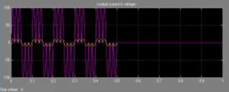
Waveform shows the output current & voltage, the input frequency is 2 times the output frequency
IJEDR1803114
International Journal of Engineering Development and Research (
www.ijedr.org
)
689
Waveform shows the output current & voltage, the input frequency is 4 times the output frequency
III.WORKING OF CYCLO-CONVERTER
The frequency can be varied by varying the conduction period for each Thyristor. The gate pulse for SCR can be provided by either by using firing circuit. Here for positive half cycle of input or supply. T1, T2‟ are forward biased, T1 is given pulse. For negative half cycle of input or supply T1‟, T2 are forward biased. T1‟ is given pulse. For another positive half cycle T2‟ is given pulse. For another negative half cycle T2 is given pulse. By using Cyclo-converter we can vary voltage and frequency. As AC motor characteristics require the applied voltage to be proportionally adjusted whenever the frequency is changed in order to deliver the rated torque this method is also called volts/hertz. For optimum performance, some further voltage adjustment may be necessary especially at low speeds, but constant volts per hertz are the general rule. This ratio can be changed in order to change the torque delivered by the motor.
IV. MODLING OF SINGLE PHASE (SPLIT PHASE) ASYNCHRONOUS MOTOR
The single coil of a single phase induction motor does not produce a rotating magnetic field, but a pulsating field reaching
maximum intensity at 0o and 180o electrical.
Fig.3 Single phase stator produces a nonrotating, pulsating magnetic field
Another view is that the single coil excited by a single phase current produces two counter rotating magnetic field phasors,
coinciding twice per revolution at 0o (Figure above-a) and 180o (figure e). When the phasors rotate to 90o and -90o they cancel
in figure b. At 45o and -45o (figure c) they are partially additive along the +x axis and cancel along the y axis. An analogous
situation exists in figure d. The sum of these two phasors is a phasor stationary in space, but alternating polarity in time. Thus, no starting torque is developed. However, if the rotor is rotated forward at a bit less than the synchronous speed, It will develop maximum torque at 10% slip with respect to the forward rotating phasor. Less torque will be developed above or below 10% slip. The rotor will see 200% - 10% slip with respect to the counter rotating magnetic field phasor. Little torque other than a double freqency ripple is developed from the counter rotating phasor. Thus, the single phase coil will develop torque, once the rotor is started. If the rotor is started in the reverse direction, it will develop a similar large torque as it nears the speed of the backward rotating phasor. Single phase induction motors have a copper or aluminum squirrel cage embedded in a cylinder of steel laminations, typical of poly-phase induction motors.
The right control method for an application of the motor run most efficiently while maximizing torque and overall performance. Efficiently run motors also use less energy and experience less downtime for greater overall savings. For motors controlled by a variable frequency drive (VFD), the control method used in large part determines a motor’s efficiency and performance in an application. There are four primary types of motor control methods for induction motors connected to VFDs: V/f (volts-per-hertz), V/f with encoder, open-loop vector, and closed-loop vector. VFDs control several different applications while maintaining optimal performance for each. The constant torque pattern is a straight line, which results in a constant V/f ratio that provides constant motor torque throughout the speed range. The variable-torque pattern has lower voltages at lower speeds to prevent motor saturation. Volts-per-hertz, commonly called V/f, is the simplest motor control method.
Single-Phase motors are not self-starting but Split-phase motors are self-starting motors. Split-phase motors are another common type of single-phase motor.
The split-phase asynchronous motor or induction motor are commonly used in major appliances such as air conditioners and clothes dryers ,washing machines, vacuum cleaners, water pumps, and used in industries as well. The split phase asynchronous motor has two windings main winding & starting winding. The starting winding is also known as auxiliary winding or running winding, which is used only for motor starting purpose. The main winding has characteristics of low resistance but high reactance. The starting winding has high resistance but low reactance.
The split phase asynchronous motor has difficulty of varying speed by a cost-effective device which is the main disadvantage of the motor.
IJEDR1803114
International Journal of Engineering Development and Research (
www.ijedr.org
)
690
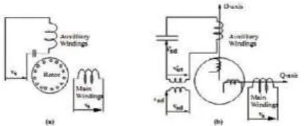
Fig 4 : D-Q transformation of the Split Phase asynchronous Motor
The simulation of the motor is presented in the stationary d-q frame to facilitate the application of the inverter. Since the axis of the main and auxiliary windings are already orthogonal, the stationary d-q axes are chosen aligned with the orthogonal axes of the physical windings. The squirrel cage rotor is represented by equivalent two coils transformed to the stationary d-q axis as shown in Fig.3. Stator windings covers two windings namely the main and auxiliary coils have different number of turns and different mutual reactance. Therefore, a transformation is made to transfer the auxiliary winding to an equivalent winding with the same number of turns as that of the main coil. The new variables referred to the equivalent coil are given as follows:-
The current equation of the motor can be written in the D-Q Stationary frame as follows:
Where,
are the D-Q stator and rotor flux linkage , respectively are the stator & rotor current, are the stator and rotor inductance, are the magnetizing inductances,
= Rotor speed, Electric radian/sec
= Developed torque
= Load torque
= Rotor moment of inertia
IJEDR1803114
International Journal of Engineering Development and Research (
www.ijedr.org
)
691
V.SIMULATION RESULT
Simulink model of Single Phase (Split Phase) asynchronous Motor and Single phase to Single phase Cyclo-converter is shown in figure.4. The objective of this paper is to study the load & Electromagnetic torque and motor speed and magnitude & phase difference of alternating source performance. For motors controlled by a variable frequency drive (VFD), the control method used in large part determines a motor’s efficiency and performance in an application.The stator of a single phase(Split Phase) asynchronous motor has two winding , the main winding & auxiliary winding(Starting or Running winding) . since the D-Q axis model of an asynchronous motor is only valid for Sinusoidal input voltage .
Fig.5 Single phase to Single phase Cyclo-converter connected with Single phase Motor
Waveform of Supply Voltage
Waveform of Output Current & Voltage, input Frequency 2 times the output Frequency
IJEDR1803114
International Journal of Engineering Development and Research (
www.ijedr.org
)
692
Waveform of main & auxiliary winding, when input frequency is 2 times the output frequency
Waveform of main and auxiliary winding, when input frequency is 3 times the output frequency
Waveform of rotor speed, when frequency is 2 times the output frequency
Waveform of rotor speed, when input frequency is 3 times the output frequency
IJEDR1803114
International Journal of Engineering Development and Research (
www.ijedr.org
)
693
Waveform of magnitude of voltage & current
Waveform of Load & Electromagnetic torque
VII.CONCLUSION
The work and study of this result is achieved, it is noted that the Load & Electromagnetic torque and speed of the motor and magnitude & phase difference of the performance of the motor can be efficiently controlled by using Cyclo-converter as a Variable Frequency drive(VFD). The Cyclo-converter varying the supply frequency then change the speed of motor and control the electromagnetic torque. Cyclo-converter is also useful to replace the flywheel from the operating machine which reduces the cause of torsional vibration and fatigue damage of machine. In this paper the simulation of load & Electromagnetic control of motor at different frequencies by using Cyclo-converter is simulated and generated the output waveforms.
REFERENCES
[1] Simulation of Cyclo-converter based Three Phase induction Motor, International Journal of AdvanceEngineering&Technology,July 2011 .
[2] http://docplayer.net/40296154-Simulation-of-cycloconverter-fed-split-phase-induction-motor.html .
[3] Power quality analysis of a three- phase cyclo-converter under variable operating condition by Kevin Palani ,June 2010 [4] Rashid, Muhammad H. Power Electronics: Circuits, Devices, and Applications. 3rd ed. Upper Saddle River: Pearson Prentice Hall, 2004.
[5] https://hansenwell.com/variable-frequency-drive .