Abstract—Composite materials have been used in considerable industrial applications due to their light weight and high strength. However, the machining costs of these materials may reach high and the grinding of these materials is much more susceptible to surface damage as compared to metals. Electrolytic In- Process Dressing (ELID) grinding can be used to machine hard and brittle materials to achieve high
surface quality and high material removal rate. In the present
work, “the Design of Experiments” (DOE) technique is developed for five factors at three levels to conduct experiments. Experiments have been conducted for measuring surface roughness based on the DOE technique in an ELID
grinding machine using a diamond wheel. The experimentally
measured values are also used to train the feed forward back propagation Neuro-fuzzy for prediction of surface roughness. The ANFIS(Adaptive Neuro-Fuzzy Interference System) predictive neuro fuzzy model was found to be capable of better predictions of surface roughness.
Index Terms - ELID grinding process, Optimization, ANFIS
I. INTRODUCTION
The ultimate aim of any machining process is production of part of a specific shape with dimensional accuracy and good surface finish. One should also keep in mind that there is minimum formation of development of any undesirable properties of the work piece. Grinding is one of the most important industrial process that is very widely used as a finishing process. In recent years, application of composite materials has increased significantly due to their light weight ratio and better mechanical properties [1]. Grinding composite materials using conventional surface grinding process shows poor surface finish and accuracy [2].
Materials those are hard and brittle, such as semi conductors, ceramics and glasses, are amongst the most challenging to machine. When attempting to machine ceramics, such as SiC, especially to improve the surface finish, it is important to carry out damage free machining operations. This often can be achieved by ductile mode machining or in other words machining a nominally hard
1
and brittle material in the ductile regime. Since the hardness of SiC is approximately 30% of the hardness of
Manuscript received April 30, 2011, revised July 26, 2011. This work was supported in part by the Annamalai University, Department of Manufacturing under Grant university department fund.
P.Babu Aurtherson is a Research Scholar in the Dept. of Manufacturing Engineering, Annamalai University, Chidambaram, India (e-mail: pbaurtherson@ gmail.com.).
S.Sundaram is now with the Department of Manufacturing Engineering , Annamalai University, Chidambaram
diamond, machining SiC with a diamond tool is an extremely abrasive process. As a result of the abrasive material removal process, there are several limitations in terms of machining parameters that have to be considered. The primary limitation in the process of ductle mode machining is to not to exceed the critical depth of cut or the DBT depth of the material. Exceeding the DBT depth during the machining process will result in fracture and thus leaving a poor surface finish. (Raveendra et.al., 2007).
To obtain better surface finish ELID grinding technique has been adopted. A good understanding of the relationship between the work materials cutting tool materials, cutting conditions and the process parameter is an essential requirement for the optimization of the grinding process [3-5]. Reportedly [6], ELID successfully assisted during grinding on brittle materials (BK-7 glass, and fused silica, ceramics, hard steels, ceramic coatings, etc.), having various shapes (plane, cylindrical external and internal, spherical and a spherical lenses, etc.) and dimensions. Extensive study have been carried out to determine the effect of ELID grinding in ductile mode on brittle materials that decreases the surface fracture and fragmentation and enables higher material removal rate [7].
ANFIS is one of the most powerful computer modeling techniques, used in many fields of engineering for modeling complex relationships which are difficult to describe with physical models. It has been extensively applied in modeling many metal cutting operations [8]. Process optimization has also been studied extensively for various manufacturing processes including grinding [9, 10]. Optimization of ELID grinding on ceramics by using the process models built with Neuro-fuzzy theory, an optimization algorithm is constructed for multiple objectives function [11]. The theory of fuzzy logics, initiated by Zadeh in 1965 [12] has proven to be useful for dealing with uncertain and vague information, and has been successfully applied in many research fields [13-16].
This research aims solving the problems in surface roughness in grinding composite materials. It is shown that the proposed method can greatly reduce the effort of the optimization procedure. Furthermore, the results of the confirmation experiments reveal that the obtained optimal combination of the grinding parameters can effectively improve surface roughness.
II. ELID GRINDING TECHNIQUE A. Principle of ELID Grinding
The schematic representation of the experimental set up of the ELID grinding process is shown in Figure 1. This module consists of an electrode, a gap adjustment
Grinding Process on AlSic composite material and
Optimization of surface roughness by ANFIS
mechanism, and a set of electrolyte injecting nozzles. The complete system is detailed below.
Fig. 1. ELID electrolysis module
Initial electrolytic process removes metal matrix of the grinding wheel to form oxide layers to let the abrasive protrude from the grinding wheel surface. As the protruded abrasives wear during grinding process, the oxide layer also becomes thinner. The wear of the oxide layer increases the wheel’s electric conductivity, oxidizing the metal bonded diamond wheel again. By this electrolytic process, the thickness of oxide layer is maintained to give stable abrasive protrusion.
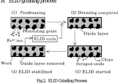
B. ELID grinding process
Fig.2. ELID Grinding Process
The steps of the ELID is shown in Figure 2 and detailed as follows.
(1)Start of Pre-dressing: Cast iron bond material is ionized into Fe+2 that is then removed by electrolyte and the super abrasive grains protrude.
TABLE 1: GRINDING PARAMETERS
Materials AlSiC (Aluminum Silicon Carbide) Al with 10%Si
Apparatus Used for Grinding
ELID (Electrolysis In process Dressing Grinding Machine)
Parameters used for Grinding
Number of Pass 50-100-150 Work Speed 200-300- 400 mm/min
Depth of Cut 2-4-6 micron Current 30-40-50 A Voltage 70-80-90 V Wheel used for grinding Diamond Wheel
(2)End of Pre-dressing: Hydration and/or oxidation of the cast iron-bonded material will form an insulation layer on
the surface of the grinding wheel and reduce the electrolytic effect until stabilization.
(3) Start of ELID Grinding Process: The grains are worn and the insulation layer is thinning while the grinding process continues.
(4) Stabilization of ELID Grinding Process: Electrolysis restarts due to the thinning of the insulation layer and insulation layer will start to be reformed until establishment, ie., stabilization recovers.
The experimental set up is shown in Fig. 3. The experiment was carried out on a precision surface grinding machine.
Fig.3. ELID machine setup
An electrode made of copper, covering 1/6 of the perimeter of the grinding wheel, was used. The metal bonded diamond wheel was mounted on a horizontal spindle and the gap between the grinding wheel and the copper electrode was adjusted to 0.2 mm. The carbon brush was made in such a way to have smooth contact with the grinding wheel shaft. The dynamometer, vice and the work piece assembly were fixed on the machine table. An electric current in the form of a square pulse wave was supplied from the ELID power supply to the positive and negative poles. A standard coolant namely CG-7 was prepared with ordinary tap water in a ratio of 1:50 and used as electrolyte and coolant for the experiment. Electrolyte was applied in between the grinding wheel and the electrode to start the electrolysis.
The experiment was performed on Al–10%SiCP composites, to study surface roughness. The surface roughness was measured with a Mitutoyo surftest.
A. Design of experiment
In this experiment with five factors at two levels each, the fractional factorial design used is a standard L18 orthogonal array. This orthogonal array is chosen due to its capability to check the interactions among factors. Each row of the matrix represents one trial. However, the sequence in which these trials are carried out is randomized. The factors and levels are assigned as in Table 1. The L18 orthogonal array is adopted for experimental layout of the machining parameters which is shown in Table 2.
TAB LE 2:L18 ORTHOGONAL ARRAY FOR EXPERIMENTAL LAYOUT Exp. No No of Pass Work Speed Depth of Cut Current Duty
Ratio Voltage
1. 1 1 1 1 1
2. 1 1 2 2 2
3. 1 1 3 3 3
4. 1 2 1 1 2
5. 1 2 2 2 3
6. 1 2 3 3 1
7. 2 3 1 2 1
8. 2 3 2 3 2
9. 2 3 3 1 3
10. 2 1 1 3 3
11. 2 1 2 1 1
12. 2 1 3 2 2
13. 3 2 1 2 3
14. 3 2 2 3 1
15. 3 2 3 1 2
16. 3 3 1 3 2
17. 3 3 2 1 3
18. 3 3 3 2 1
IV. ADAPTIVE NETWORK BASED FUZZY INFERENCE SYSTEMS (ANFIS)
Predicting accurately the quality of the machining parts and finding the optimal process parameters is very vital; this is needed to build a model of the complete grinding process. It combines the advantages of fuzzy logic (FL) and ANNs, Starts with an initial FL structure and uses ANN for adapting the FL (MF) parameters and the rule base to the training data. It is shown in Fig 3. Adaptive Network-based Fuzzy Inference System (ANFIS) technique was originally presented by Jang, [10] in 1992. The model uses neuro-adaptive learning techniques, which are similar to those of neural networks. Given an input/output data set, the ANFIS can construct a fuzzy inference system (FIS) whose membership function parameters were adjusted using back-propagation algorithm or other similar optimization techniques. This allows fuzzy systems to learn from the data they are modeled. For simplicity, assume the fuzzy inference system with two inputs, p and q with one response, f. From the first-order Sugeno fuzzy model, a typical rule set with two fuzzy if–then rules can be expressed as
Fig.3. ANFIS architecture for a two rule Sugeno system
A Two Rule Sugeno ANFIS has rules of the form:
1 1 1 1 1
1andyisB THEN f px q y r
A is x
If = + +
2 2 2 2 2
2 and yisB THEN f p x q y r A
is x
If = + +
For the training of the network, there is a forward pass and a backward pass. We now look at each layer in turn for
the forward pass. The forward pass propagates the input vector through the network layer by layer. In the backward pass, the error is sent back through the network in a similar manner to back propagation
Layer 1
The output of each node is:
2 , 1 ) ( ,
1i= Ai x fori=
O μ 4 , 3 ) ( 2 ,
1i = Bi− y fori=
O μ
So, the O1,i(x) is essentially the membership grade for
x
andy
.The membership functions could be anything but for illustration purposes we will use the bell shaped function given by: i b i i A a c x x 2 1 1 ) ( − + = μ
where
a
i,
b
i,
c
iare parameters to be learnt. These are the premise parameters.Layer 2
Every node in this layer is fixed. This is where the t-norm is used to ‘AND’ the membership grades - for example the product:
2
,
1
),
(
)
(
,2
=
w
=
x
y
i
=
O
i
i B
A i
i
μ
μ
Layer 3
Layer 3 contains fixed nodes which calculate the ratio of the firing strengths of the rules:
Layer 4
The nodes in this layer are adaptive and perform the consequent of the rules:
)
(
,
4i
w
if
iw
ip
ix
q
iy
r
iO
=
=
+
+
The parameters in this layer (
p
i,
q
i,
r
i ) are to be determined and are referred to as the consequent parameters.Layer 5
There is a single node here that computes the overall output:
∑
∑
∑
==
i i
i i i
i i i i w f w f w O5,
V. ANFIS USED FOR OPTIMIZATION OF MACHINING PARAMETERS
The ANFIS based approach is used for optimization, since it uses the advantages of both fuzzy logic and neural network. The main difference between fuzzy sets and ANFIS is the fuzzy sets having decision making only ,but ANFIS having knowledge based decision making. Fig. 4
illustrates the basic structure of the ANFIS with five inputs (ie., Number of pass, Work speed, Depth of cut ,Current and Voltage) and one output called surface roughness.
Fig 4: Basic Structure of ANFIS with five inputs
(a)
(b)
( c)
(d)
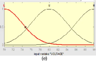
(e)
Fig .5 Membership functions for input variables
Here the fuzzy logic creates a proper modification in the input variable with the knowledge of Neural network. In the ANFIS, rules are automatically created and the fuzzy sets are represented by membership functions which are illustrated by Fig. 5. Three fuzzy sets are selected for the variables of inputs (L,M,H), and 243 fuzzy sets are used for the surface roughness, Sugeno type fuzzy is used in the output. In this study, the Gaussian membership functions are used for both input and output variables because of their accuracy. Selection of the number of membership functions and their initial values is based on the system knowledge and the experiment conditions.
TABLE 2COMPARISONS OF EXPERIMENTAL RESULTS WITH ANFIS
Sl no No of
pass
Work speed Depth of
cut
Cu
rren
t
Voltage
Surface roughness
Ex
peri
me
nt
al
AN
FIS
Er
ro
r
1 50 200 2 30 70 1.59 1.540 3.24 2 50 200 4 40 80 1.44 1.442 0.180 3 50 200 6 50 90 0.91 0.941 3.47 4 50 300 2 30 80 1.28 1.181 0.109 5 50 300 4 40 90 1.46 1.457 0.198 6 50 300 6 50 70 1.52 1.547 1.82 7 100 400 2 40 70 1.58 1.552 1.74 8 100 400 4 50 80 1.32 1.300 1.51 9 100 400 6 30 90 0.96 0.971 0.25 10 100 200 2 50 90 1.07 1.068 0.177 11 100 200 4 30 70 1.57 1.571 0.07 12 100 200 6 40 80 1.42 1.416 0.246 13 150 300 2 40 90 1.16 1.163 0.301 14 150 300 4 50 70 1.46 1.458 0.075 15 150 300 6 30 80 1.54 1.541 0.123 16 150 400 2 50 80 0.96 1.968 0.310 17 150 400 4 30 90 1.31 1.316 0.458 18 150 400 6 40 70 1.46 1.478 1.287
VI. RESULTS AND DISCUSSION
parameters (Number of pass, work speed, depth of cut, current and voltage) given in table1. The effect of each input parameters has been studied on the surface roughness. Of the 200 and odd data collected experimentally, only 18 sets of data which is collected as per Tauguchi method of orthogonal array are presented in table 2. In these 18 sets of readings, the number of process has been varied from 50 to 150, work speed from 200mm/min to 400mm/min, the depth of cut from 2 micron to 6 micron, the current to 30 to 50 amps, the voltage from 70 to 70 volts. The Experimental surface roughness and as per the ANFIS model were found out and are reported in table 2.
A. Effect of ‘Number of Passes’ and ‘Depth of cut’ on surface roughness
The surface roughness was measured, varying the number of passes from 50 to 150 and the depth of cut 2 to 6 microns, while maintaining the other parameters like work speed, current and voltage constant. It has been found that the optimum surface roughness has been obtained with the depth of cut of 2 microns and the number of process 150. The optimum value of surface roughness obtained experimentally was further confirmed by ANFIS model also. The experimental and ANFIS results obtained for Number of passes and depth of cut plotted in Fig 6(a).
Fig.6 (a) Comparison of Experimental and ANFIS result on various Depth of cut
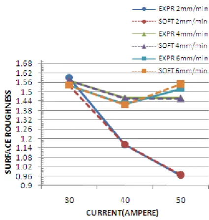
B. Effect of current and Depth of cut on surface roughness
The current varied from 30A to 50 A and the Depth of cut from 2 micron to 6 micron, while maintaining the other parameters constant and surface roughness was measured every time. It has been observed that the surface roughness has been negatively affected with the increase of current. However, the optimum surface roughness has been obtained at 50 A current, and at 2 micron depth of cut. This optimum experimentally obtained surface roughness value was confirmed by ANFIS model also. The values are plotted in Fig. 6(b) for comparison.
Fig. 6(b) Comparison of Experimental and ANFIS result on various Depth of cut
C. Effect of Voltage and Depth of cut on surface roughness
Fig.6(c) Comparison of Experimental and ANFIS result on various Depth of cut
The Voltage was varied from 70V to 90V and the Depth of cut from 2 micron to 6 micron and experiments were repeated. The other parameters were kept constant while carrying out the experiment. The surface roughness has been found to be negatively affected when the voltage was increased. However, the optimum surface roughness was obtained at 90 voltages and at 2 micron Depth of cut, which was confirmed by ANFIS model also. The values obtained or plotted in Fig. 6(c) for comparison
D. Rule Viewer
passes, 30 mm/min, and 4 micron Depth of cut, 40 Amps current And 80 Volts in given Fig. 7.
Fig: 7 Rule viewer for Surface Roughness
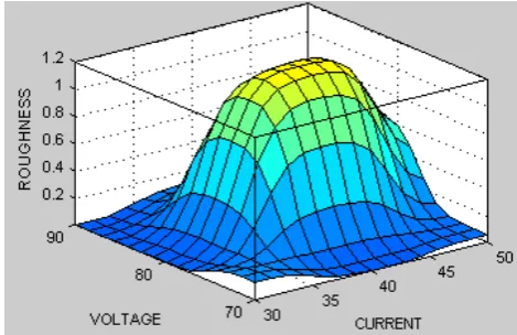
Fig: 8(a) Surface viewer
Two typical surface viewers have been provided in Fig. 8 (a) and 8 (b). In Fig 8 (a) the surface roughness has been plotted against current and work speed and Fig 8(b), it has been plotted against voltage and current. The surface roughness in Fig 8 (b), for the given input parameters of voltage and current was found to be better whereas, the surface was poor in comparison, when the input parameters were current and work speed, as Fig 8 (a).
Fig 8(b) Surface viewer
VII. CONCLUSION
ANFIS model has been used for optimizing the surface roughness in ELID machining process. Five machining parameters namely Number of pass, Work speed, Depth of cut, Current and Voltage were considered as the input parameters. Surface roughness was taken as the output parameter. Experimental investigations were carried out with 18 sets of input parameters. The same input parameters were given as the input for the ANFIS model. The surface roughness values obtained through ANFIS model where optimized and trained. The trained values were compared with the experimental values for validating the ANFIS Model. It has been found that the result obtained through ANFIS model were comparable with the values, obtained experimentally, with acceptable error, which proves the ANFIS model is capable of predicting the optimized value of surface roughness.
REFERENCES
[1] B. Anand Ronald, L. Vijayaraghavan , R. Krishnamurthy, Studies on the influence of grinding wheel bond material on the grindability of metal matrix composites, Materials and Design, 30, 2009, 679–686. [2] Aguiar, P. R. et al., “A integridade superficial da peça monitorada
por emissão acústica e potência elétrica no processo de retificação (in Portuguese)”. 8as Jornadas Portuguesas de Tribologia – Novos Desenvolvimentos da Tribologia: Análise Teórica e Aplicada em Processos Industriais. Universidade de Aveiro, Portugal, 08 e 09 de maio de 2002. pp. 245 - 249.
[3] P. R. Aguiar, F. R. L. Dotto and E. C. Bianchi, Study of Thresholds to Burning in Surface Grinding Process, Journal of the Brazil Society of Mechanical Science & Engineering, 27:2, 2005, 150-156.
[4] Bandyopadhyay, B.P., Ohmori, H., and Takahashi, I.,Efficient and Stable Grinding of Ceramics by Electrolytic In-Process Dressing (ELID), Journal of Material Processing Technology,. 66, 1997, 18-24. [5] [5] Ohmori, H. and Nakagawa, T., Mirror Surface Grinding of Silicon Wafers with Electrolytic In-Process Dressing, Annals CIRP, 39:1, 1990, 329-332.
[6] Ohmori, H., Takahashi, H., and Bandyopadhyya, B.P., Highly Efficient Grinding of Ceramic Parts by Electrolytic In-Process Dressing (ELID) Grinding, Materials Manufacturing Process.,11:1, 1996, 31-44.
[7] Spanu, C., and Marinescu, I., 2002, Effectiveness of ELID Grinding and Polishing. International Manufacturing Conference IMTS: Chicago.
[8] Bandyopadhyay, B.P. and Ohmori, H., “The effect of ELID grinding on the flexural strength of silicon nitride,” International Journal of Machine Tools Manufacturing, 39, 1999, 839-853 .
[9] Kumanan, S. Jesuthanam, C. P. and Ashok Kumar, R, Application of multiple regression and adaptive neuro fuzzy inference system for the prediction of surface roughness, International Journal of Advance Manufacturing Technology, 35, 2008,778–788.
[10] Konig, W. and Wemhoner, J, Optimizing Grinding of SiSiC, Ceramic Bulletin, 68:3,1989, 545-548.
[11] Nian, C.Y. Yang, W.H. and Tarng, Y.S., Optimization of Turning Operations with Multiple Performance Characteristics, Journal of Material Processing Technology, 95, 1999, 90-96.
[12] Chang-Pin Lin. Kuei-Miao Hsiao. and Chun-Chung Wu., Parameter Analysis and Optimization of Electrolytic In-Process Dressing Grinding on Ceramics, Journal of Marine Science and Technology, 11:2,2003, 104-112.
[13] Park, S.H. (1996). Robust Design and Analysis for Quality Engineering, Chapman & Hall, London.
[14] Nestler,A. Fichtner,D. Schulz,G., An approach to technological database – possibilities for the determination of cutting values with neural networks, Flexible Automation Intelligent Manufacturing., 2, 1998, 577–586.
[15] Karri,V, Performance in oblique cutting using conventional methods and neural networks, Neural Computing. Applications, 8, 1999, 196– 205.