- 146 -
Abstract— Mobility and Quality of Service(QoS) plays a vital role in the Wireless networks based on the IEEE 802.11 protocol family.When mobile systems move across heterogeneous networks, ongoing real time sessions are affected not only by handoff delay but also by jitter. With respect to this scenario, we describe the features to enhance mobility by reducing the handoff latency along with reduced packet loss across the heterogeneous networks such as WLAN and UMTS by comparing the predicted rss (received signal strength) against two thresholds calculated by the mobile terminal (MT) to make handoff decision. The packet losses can be reduced by having jitter buffer with some extra delay added. Handoff speed can be improved by having pre-handoff notification using CoA (Care of Address) maintained in each router and hence the binding updates to home agent and correspondent node are performed once Previous Access Router knows a mobile node’s new CoA. By this during handoff only the node movement happens hence reducing handoff latency.
Index Terms— Mobility, voice over IP, pre-handoff, received signal strength, Heterogeneous wireless networks.
I. INTRODUCTION
One of the most important challenges in Mobile IPv6 is to provide the service for a mobile node to maintain its connectivity to the Internet when it moves from one domain to another, which is referred to as handover. Here we deal with the fast handover problem, which is to provide rapid handover service for the delay-sensitive and real-time applications.To make a mobile node (MN) stay connected to the Internet regardless of its location, mobile IPv6 is proposed as the next generation wireless Internet protocol as in [1]. This is achieved primarily through using CoA (Care of Address) to indicate the location of the MN. Although the Mobile IPv6 protocol has many promising characteristics and presents an elegant mechanism to support mobility, it has an inherent drawback. That is, during a handover process, there is a short period that the mobile node is unable to send or receive packets because of link switching delay and IP protocol operations.
Handover is the process by which an MN keeps its
Manuscript received July 10, 2009. V. Berlin Hency is with the Madras Institute of Technology, Lecturer, 600044 India, +919884317349;
Preetha E, Vadivelan M., Saranya K are the final year BE (Computer Science) students of MIT campus, Anna University,Chennai,India.
Dr. D. Sridharan is with the Department of Electronics and Communication Engineering, Anna University, Chennai, 600044 India, (e-mail: [email protected]).
connection active when it moves from one access medium to another. The handover process happens when the MN moves one access medium to another, and it should accomplish three operations: movement detection, CoA configuration, and binding update (BU) as in [7]. The problem which is prevailing with handover of mobile node from a network to another network is the delay in time taken for the mobile node to move to the new network, time taken for authentication process and time taken for registration with the new network. Normally mobile node has to register whenever it is entering new network. In addition to that previous access router (the router of network in which mobile node was present before handoff) has to send all the routing information about that mobile node (which it is previously having )to access router of new network.
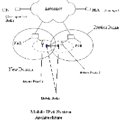
Fig 1 Mobile IPv6 System Architecture
The problem with this is it causes additional delay during handover. That is time to register and time taken by the previous access router in transferring the network parameters to the new access router. In order to avoid this delay, we have to make the previous access router to transfer the network parameters to new access router in prior to handover of the mobile node. This reduces the delay in handover because it involves only the registration of the mobile node to new network
II. BACKGROUND
In cellular telecommunications, the term handoff refers to
Enhancement of Handoff Speed by Improving
Mobility of Data Packets
- 147 - the process of transferring an ongoing call or data session from one channel connected to the core network to another. In satellite communications it is the process of transferring satellite control responsibility from one earth station to another without loss or interruption of service.
One can carry out a Handoff in the following way: level 3 (Network layer) Handoff and level 2 (Connection layer) Handoff, according to the OSI model. The layer 2 Handoff is the operation carried out by a Mobile Node, which changes of radio access point. This Handoff can generate or not a Handoff of superior layer according to the wired connection of radio access points (if those are on the same net connection or not).
In the case of a Handoff of level 3, Mobile Node needs to acquire a new IP address. It requires registration messages, which can cause a communication interruption. The time of interruption can increase if the number of users increases. This will be awkward for the real times applications or delay sensitive traffic (like the voice over IP, video streaming).That's why a certain number of mobility protocols were presented to improve the performances of Mobile IP and in particular the Handoff process as in [7]. These protocols are made for environments where the MIPv6 specifications are insufficient: signalization overload, packets loss, and data delivery delay. These delays are directly related to the round-trip time of registration messages.
A. Background of IPv6
To solve the mobility problem of IP a standard was proposed, namely mobile IP. The components of the mobile IP protocol are:
MN: Mobile Node (sometimes called Mobile Host), this is the node that changes location.
HN: Home Network, the network in which the Mobile Nodes (MN) home agent is positioned. This is the network in which the permanent address of the MN is located.
HA: Home Agent, which is in the router of the Home Network (HN).
FN: Foreign Network, the network that the MN is currently in.
FA: Foreign Agent, which is in the router of the Foreign Network (FN).
CN: Corresponding Node (sometime called
Corresponding Host), the node that the MN is communicating with.
CoA: Care-of-Address, the temporary IP address that the Home Agent (HA) can use to contact the MN, while it resides in the FN. This CoA usually points to the Foreign Agent (FA), although it might sometimes point directly to the MN.
B. Literature Survey
In [11] the authors have taken globally accepted model of integration between WLAN and UMTS because of the reason that Integration of two different networks is possible only when their corresponding network parameters such as pre-authentication, pre-registration, network attachment and detachment delay times coincide. For these two networks normal time for a mobile node to make handover is 2.5s
which includes pre-authentication time as 1 s and pre-registering time as 1 s and for each network attachment and detachment delay it takes 0.2s each. And an additional network delay of 0.1 s. So as a whole it takes 2.5 s. This is the normal latency being occurred in handover process. But our method reduces the time taken for authentication and registration in prior before actual handover happens thereby bringing down the latency around 2 s.
Streaming systems rely on buffering at the client to protect against the random packet losses and delays that characterize a best-effort network. These parameters vary depending on the locations of the senders and the receivers; with typical loss rates of 0-20% and one-way delays of 5-500 ms, [12]. Buffering reduces a system’s sensitivity to short-term fluctuations in the data arrival rate by absorbing variations that is called jitter. The main objective of jitter buffering is to keep the packet loss rate under 5% and to keep the end-to-end delay as small as possible. By maintaining the buffer at the receiving side, we can introduce the buffer delay which in turn reduces the no of packets being lost from 5-20% to below 10% by considering the various cases including spike detection case because the algorithms discussed until now in [12] do not adapt fast enough to such spikes, taking too long to increase their delay estimate on its detection and too long again to decrease their estimate once the spike is over. An algorithm is described to adapt to such spikes. That is called spike detection algorithm.
III. PERFORMANCEANALYSIS
Check whether the packet count exceeds hold_sequence if so,
Delay = ( time duration-hold time) /( packet count –
hold sequence )
Else
Delay = | packet count – hold sequence|
Update the variables now, hold_sequence, hold_time according to current values and proceed with further calculations.
- 148 -
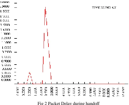
Fig 2 Packet Delay during handoff
Normally the packet delay will be 0.1 milliseconds. Here the packet delay during handoff increases up to 2 ms and it retains for about 0.6 seconds.Before that a small delay when the mobile terminal starts receiving information occurs. Once the new network path is dedicated for the new mobile terminal, then the packet delay will be normal 0.1ms thereafter till next handoff occurs.
Pre-handoff will resemble that there is less packet delay until the information about the mobile terminal are sent to the new access router. And also during handoff, only movement of mobile terminal happens. Binding updates are done prior once the handoff is predicted.
Comparison:
Now with pre-handoff, the delay as usual increases upto 2 ms during handoff but retains only for 0.3 s. Hence the handoff latency is reduced as half of the original handoff latency. So the Handoff speed is increased some extent due to this pre-handoff.
Comparison of Success handover with handover delay:
The handover decision method relies on an algorithm which attempts to predict the travelling distance in a WLAN cell coverage area by using the change rate of RSS. The relationship between RSS( in mW) and the distance between access point (AP) and the MT at any point inside the WLAN coverage area can be obtained by using the path loss model as in [10]
Fig 3 Packet Delay with pre-handoff
RSS = E*l^ -β*10^ (ε/10)
where E( in mW) is the transmit power of the AP, β is the path loss exponent ( a value between 2 and 4 chosen depending on the transmission environment), and ε is a Gaussian distributed random variable with a mean of zero and a standard deviation up to 12 dB.Here the power being transmitted can be calculated using the formula
Transmit Power = N (λ (packets/s)*L(bits)) /R(bps)
Where N is the number of connections, λ is the transmission rate, L is the packet size, R is the bandwidth.
As speed (distance) increases, the rate of RSS decreasing increases, in such scenario the probability of successful seamless service decreases( or affected greatly).In such case, ordinary handover scheme fails shown in fig 4.a.
In such case, our scheme will increase the probability of successful handover by greatly reducing the delay( or time taken to make the handover) shown in fig 4.b. For a successful handover rate of RSS decreasing should be greater than the delay (or time taken to make the handover).
Averagedelay=(T*suc_prob)+(t*(1-suc_prob))+(dist/vel)
where T is time taken for successful handover, t is time taken for unsuccessful handover.
- 149 - Integration of two different networks is possible only when their corresponding network parameters such as pre-authentication, pre-registration, network attachment and detachment delay times should coincide. For such reason we have taken globally accepted model of integration between WLAN (Wireless LAN) and UMTS (Universal Mobile Telecommunication System).WLAN is known for its wider coverage area whereas UMTS is for higher data rate. Integrating these two networks provides better throughput and good communication quality. For these two networks normal time for a mobile node to make handover is 2.5s which includes pre-authentication time as 1s and pre-registering time as 1s and for each network attachment and detachment delay it takes 0.2s each. And an additional network delay of 0.1s. So totally 1+1+0.2+0.2+0.1=2.5s. This is the normal latency being occurred in handover process. But our method reduces the time taken for authentication and registration as they started in prior before actual handover happens thereby bringing down the latency around 2s.
IV. BUFFER MANAGEMENT
A typical VoIP application buffers incoming packets at the receiver and artificially delays their playout in order to compensate for variable network delays called jitter. If the buffering delay is set too large, the overall latency increases to a level where interactivity of the conversation suffers; if it is set too small, the resulting increased packet loss rate decreases the perceived voice quality. The two conflicting goals of minimizing buffering delay and minimizing late packet loss have led to various adaptive playout algorithms. Most of the adaptive playout algorithms described in the literature depend on estimates of network delays to calculate playout deadlines of already received packets. Good network estimators should ignore transient noise conditions, but react quickly to persistent changes in performance.
Case 1: Linear
The delay estimate for the ith packet and a measure of the variation in the delays is calculated as in the calculation of round trip time estimates for the TCP retransmit timer. Specifically the delay estimate for packet i is computed as
di. = α*di-1. + (1-α)*ni
and the variance is computed as
vi. = α*vi-1. +(1-α)*|di - ni |
Where ni is network delay and di is packet delay.
This algorithm is basically a linear recursive filter and is characterized by the weighting factor α = 0.125.
Case 2: Varient
The idea is to use a different weighting mechanism by choosing two values of the weighting factor, one for increasing trends in the delay and one for decreasing trends.
Variation estimate is calculated as in case 1. The delay estimation algorithm is given as
if (ni > di.) then
di. = β* di.+(1-β)*ni
else
di. = α*di.+(1-α)*ni
Where the weighing factor β =1- α.
Case 3: Minimum with spike detection
Delay spikes are a common occurrence in the Internet. A spike constitutes a sudden, large increase in the end-to-end network delay, followed by a series of packets arriving almost simultaneously, leading to the completion of the spike. The algorithms discussed until now do not adapt fast enough to such spikes, taking too long to increase their delay estimate on detection of a spike and too long again to decrease their estimate once the spike is over. An algorithm is described to adapt to such spikes. This algorithm is called spike detection algorithm
1. n i = Receiver timestamp -Sender timestamp
2. if (mode==Normal) {
if (abs(ni - ni-1) > abs(vin)*2+800 /* Detected
Beginning of a spike*/
slp = 0 ;
mode = IMPULSE ; }
Else {
slp = slp/2 +abs (( 2ni-ni-1-ni-2 ) / 8);
if (slp <=63){ /*End of a spike*/
mode = NORMAL;
ni-2 = ni-1;
ni-1 = ni;
Return;}
}
3. if (mode == NORMAL) then
del i = 0.125*ni +0.875* di-1.;
Else
deli= di-1 + ni-ni-1 ;
vini = 0.125*abs(ni -del i) + 0.875 * vi-1;
4. ni-2 = ni-1;
ni-1 = ni;
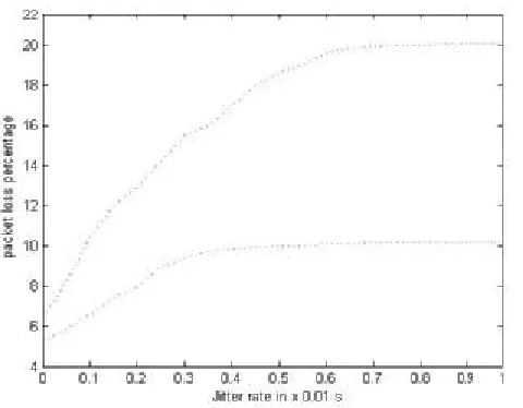
- 150 - Fig 5 Comparison of packet loss percentage with jitter rate
By maintaining the buffer at the receiving side, we can introduce the buffer delay which in turn reduces the no of packets being lost from 5-20% to below 10% by considering the various cases including spike detection
V. CONCLUSION
Mobility manager module on the mobile device is to provide information about network parameters and handoff events. Our work has an advantage that our scheme doesn’t require changes to existing network infrastructures and relies on existing protocols only. Jitter buffer delay is increased for some amount to reduce the packet loss [1]. The probability of handoff failures and unnecessary handoff are reduced much by using the thresholds of received signal strength [10]. Each access router maintains a CoA table, and generates a new CoA for a mobile terminal that is anticipated to move to its domain. Binding updates to Home Agent/Correspondent Node are performed by previous access router (PAR) from the time point when the nCoA is known by PAR. Hence due to this pre-handoff scheme, the handoff latency and packet delay are much reduced [7].
Hence by combining all these features and methods, the handoff latency and packet delay are much reduced. This will finally enhance handoff speed through mobility of data packets.
Our work is concerned mainly with respect to two networks only namely WLAN (Wireless LAN) and UMTS (Universal Mobile Telecommunication System), so the future work should be done considering most of all possible networks so that heterogeneity can be maintained across various networks.
In our work, we proposed fixed dynamic algorithm by taking into account only two weighing factors namely alpha and beta by considering 3 cases. As a future work, dynamically changing weighing factors needs to be proposed which should be adaptable for most dynamic environment
REFERENCES
[1] Massimo Bernaschi, Filippo Cacace, Giulio Lannello, Member,IEEE,
and Massimo Vellucci, “Mobility Management for VoIP on
Heterogeneous Networks: Evaluation of Adaptive Schemes”, vol 6 No 9 September 2007,pp 1041-1045.
[1] Younchan Jung, The catholic university of Korea., J.William Atwood, Concordid university, “Switching between Fixed and Call-Adaptive Playout: A per-Call Playout Algorithm”, IEEE Internet Computing, July 2005, pp 23-26.
[2] Miroslaw Narbutt, Dublin Institute of Technology, Andrew Kelly, Liam Murphy and Philip Perry, University College Dublin, “Adaptive VoIP Playout Scheduling: Assessing User Satisfaction”.IEEE Internet Computing, July-August 2005,pp 29-31.
[3] Michael Manousos, Spyros Apostolacos, loannis Grammatikakis and Dimitrios Mexis in Access Networks, Dimitrios Kagklis and Efstathios Sykas, National Technical University of Athens, “Voice-Quality Monitoring and Control for VoIP”.
[4] ]Massimo Brenashi, Italian National Research Council, “Seamless Internetworking of WLANs and Cellular Networks: Architecture and Performance Issues in a Mobile IPv6 Scenario”.
[5] Stephen Rein, Technical University Berlin, Martin Reisslein, Arizona State University, “Voice Quality Evaluation in Wireless Packet Communication Systems: A Tutorial and Performance Results for ROHC”.
[6] Ruidong Li, Student Member,IEEE, Jie Li*,Senior Member,IEEE, Kui Wu, member,IEEE,Yang Xiao,IEEE,“An Enhanced Fast Handover with Low Latency for Mobile IPv6”,vol 7,no 1,January 2008.
[7] Tudor Golubenco “Application Layer Handover of VoIP sessions in IMS Environments”, 2008.
[8] M.Narbutt*, L.Murphy* *Department of Computer Science University College Dublin Belfield, Dublin 4, Ireland, “Adaptive playout algorithms”.
[9] “A Travelling Distance Prediction Based Method to Minimize Unnecessary Handovers from Cellular Networks to WLANs” vol 12 No 1 January 2008
[10] ]Hyun-Ho Choi and Dong-Ho Cho “TAKEOVER: A New Vertical Handover Concept for Next-Generation Heterogeneous Networks” Korea Advanced Institute of Science and Technology (KAIST).
[11] M. Narbutt, L. Murhpy, “Adaptive Playout Buffering For
Audio/VideoTransmission Over the Internet”, University College Dublin, Dublin,Ireland,2000.
V.Berlin Hency Received her BE degree in Electronics and communication Engineering from Manonmaniam Sundaranar University India, ME degree in Applied Electronics from Sathyabama University India, Pursuing her PhD Degree in Information and Communication Engineering from Anna University,India. She is working as a lecturer in MIT campus, Anna University, Chennai, India. Her research interests include
wireless multimedia networks, mobility
management, mobile computing, and mobile IP.She is a member of IACSIT and the life member of Indian Society for Technical Education(ISTE)
Preetha E, Vadivelan M, Saranya K are the final year BE (Computer Science) students of MIT campus, Anna University,Chennai,India.
Dr.D.Sridharan received his B.Tech. degree in Electronics Engineering and M.E.degree in Electronics Engineering from Madras Institute of Technology, Anna University in the years 1991 and 1993 respectively He got his Ph.D degree in the Faculty of Information and Communication Engineering, Anna University in 2005. He is currently working as Assistant Professor in the Department of Electronics and Communication Engineering, CEG Campus, Anna University, Chennai, India. He was
awarded the Young Scientist Research