Innovative Technique of Power Generation by
Multiple Pedaling
Mohammad A. Hossain
Department Mechanical Engineering Prairie View A&M University, Texas, USASamarita Sarker
Department of Civil and Environmental Engineering Prairie View A&M University, Texas, USA
Asif Tanveer
Department of Mechanical Science and Engineering University of Illinois at Urbana-Champaign, Illinois, USA
Abstract- 'Power generation by using multiple pedaling’ is fabricated using local technology and available materials. It uses human energy to produce electricity. It’s potentiality in the field of micro level electricity generation is quite significant. Here an alternator is connected to a belt-pulley and chain-sprocket arrangement in a rigid structure. The input rotation is given on the pedal and final rotational speed is obtained in the alternator rotor that consecutively produces current. A new and improved technique is developed through this project that is a single shaft can be coupled by multiple pedal which not only reduce individual’s afford but also helps to generate more power by engaging more people on this work. ‘Power Generator by multiple pedaling’ can be an attractive renewable energy source for the production of electricity. In the developing country like ours, it can be used in the villages as useful source of power for a small family where the family members themselves can charge the battery by pedaling daily for a short period of time. It can be used for partial power supply in gymnasium, apartment, school and other public places. This will not only provide electricity according to their need but also provide a useful way of physical exercise and a handsome amount of payment to them which can be good source of income for the poor people. Due to the low manufacturing cost and very low maintenance effort, wide scale application “Power generation by multiple pedaling” can be a suitable source of renewable energy instead of solar panel. we are successful to reduce the production cost up to 30% compare to the production of solar panel.
Keywords- alternator, current, human afford, multiple pedaling, solar panel
I. INTRODUCTION
II. STRUCTURE OF MULTIPLE PEDALING UNIT 2.1 Major components-
• Rickshaw/Bicycle framework • Chain-drive system
• Belt-pulley system for transmission • Alternator with DC output and regulator • Battery
2.2 Working Principal-
The entire system can be divided into three steps of energy conversion. First, the human muscle energy is converted into mechanical energy through pedaling. This mechanical energy is represented in the form of rotation of chain-sprocket system. Second, the mechanical energy is transferred through the chain drive and converted to electrical energy in the alternator. Finally, the electrical energy is stored in the battery as chemical energy.
2.2.1 Conversion of energy-
The mechanical energy is produced by the cycling action. The rotation of the larger sprocket (with the pedals) drives the smaller sprocket on the rear shaft. Motion and power are transferred with the help of a chain. The chain pulley system has a teeth ratio of 48:22. The shaft rotates and rotates a large pulley, which drives the smaller pulley of the alternator with the help of a belt drive. The belt pulley has a diameter ratio of 18:2. This ratio is chosen so to attain the charging speed of the alternator, which is around 1000 to 1200rpm. This reduces pedaling effort. Conversion from mechanical energy to electrical energy is done with the help of an automotive alternator. An alternator is simply an electromechanical device used to convert mechanical energy to electrical energy in the form of alternating current. Since battery charging needs DC voltage, a rectifier is used to convert the AC current to DC current. This is done by the battery. As the alternator generates the charging voltage, terminals of the battery connected to the alternator draws in charging current and the battery charges itself, and stores the energy in chemical form. The typical chemical reaction that occurs in an automotive lead-acid battery (similar to one used in experiment) is shown below-
Discharge
PbO2 + Pb + 2H2SO4 2PbSO4 + 2H20
Charge
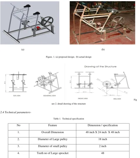
2.3 Main Structure
(a) (b)
Figure. 1. (a) proposed design; (b) actual design
Fig
ure 2. detail drawing of the structure
2.4 Technical parameters-
Table 1. Technical specification
No Feature Dimension / specification
1. Overall Dimension 48 inch X 24 inch X 48 inch
2. Diameter of Large pulley 18 inch
3. Diameter of small pulley 2 inch
4. Teeth no of Large sprocket 48
5. Teeth no of small sprocket 22
6. Centre Distance between pulley 17 inch
7 Height of hand rest 48 inch
9. Alternator Driving belt Belt No: A 68
10. Storage Battery Brand : Non brand , 35 AHr-12V Battery
11. Alternator 60 Amp-12V, Automotive type.
2.5 Power transmission-
The design of the system is such that there are two stages of power transmission needed to reach the minimum effective charging speed of the alternator. The first transmission occurs by a chain-sprocket system and the second by a belt-pulley system which in turn is connected to a single rotating shaft. When the user pedals, the large sprocket is rotated at a speed equal to the rotation of the pedal. This large Sprocket has 48 teeth. The large sprocket is connected by a chain to the small sprocket of 22 teeth.
Let the large sprocket rotate at a speed N1 and the small sprocket rotate at a speed N2. So the relation of the rotation of the two sprockets is-
22 48 1 2 = N
N (1)
Now the small sprocket has the same shaft with the large pulley of the belt pulley system. So the large pulley rotates at the same speed as the small sprocket. So if the speed of the large pulley is N3 then-
N2 = N3 (2)
Here diameter of the large pulley is 18 in and small pulley is 2 in; let the speed of the small pulley is N4. So
2 18
3 4 = N
N (3)
Now as the small pulley is coupled with the alternator so the speed of the small pulley will ultimately be the speed of the alternator. Form equation 1, 2 and 3 speed of the alternator
63 . 19 2 18 22 48 1
4 = × =
N N
Therefore, the ultimate speed multiplying factor = 19.63
If pedal rpm is 60, then alternator rpm becomes 60x19.63 = 1177. Rpm are calculated and verified using a contact-type tachometer.
2.6 Belt pulley selection-
Known data,
Diameter of Larger pulley, d1 = 18 in = 45.72 cm Diameter of small pulley, d2 = 2 in = 5.08 cm
Centre distant between two pulley, c = 17 in = 43.18 cm Then, length of the belt, L =
c
d
d
c
d
d
4
)
(
2
2
2 2 1 2 1−
+
+
+
π
= 176 cm (~70in)III. RESULTS
• Generated voltage and current from the alternator. • Open circuit voltage (OCV) of the battery. • Specific gravity of the battery electrolyte
The performance test results regarding various parameters, data table and graphs are shown below.
Table 2.1 Observation for a single person pedaling Table 2.2 Observation for double person pedaling
Obs NO:
Time(min) Voltage(Volt) Avg Voltage
(Volt)
Current (amp)
Power (Watt)
Obs NO:
Time(min) Voltage(Volt) Avg Voltage
(Volt)
Current (amp)
Power (Watt)
1 1 12.38-12.45 12.41 3.5 43.57 1 1 12.32-12.52 12.42 4.75 58.9 2 1 12.36-12.62 12.49 2 25.24 2 1 12.38-12.64 12.51 3.63 45.4 3 1 12.58-12.70 12.64 2.2 27.94 3 1 12.56-12.68 12.62 3.28 41.1 4 1 12.57-12.75 12.66 2 25.5 4 1 12.58-12.72 12.65 3.14 39.7 5 1 12.64-12.80 12.72 2.1 26.88 5 1 12.62-12.78 12.70 3.00 38.1 6 1 12.72-12.78 12.75 2.2 28.05 6 1 12.66-12.76 12.71 3.12 39.6 7 1 12.75-12.79 12.77 2 25.54 7 1 12.69-12.78 12.73 3.08 39.2 8 1 12.74-12.78 12.76 2.1 26.8 8 1 12.72-12.80 12.76 3.10 39.5 9 1 12.78-12.92 12.85 2.3 29.55 9 1 12.75-12.84 12.79 3.00 38.3 10 1 12.75-12.86 12.80 2.2 28.17 10 1 12.78-12.85 12.81 3.13 40.1
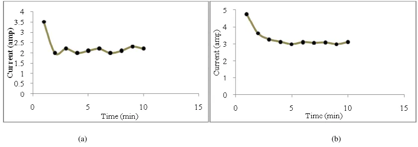
Initially there is a large amount of current flow which is known as surge current. As time passes current become stable and power varies with the current flow. Terminal Voltage varies with current and if the battery is fully charged then it with show approximately 12.80 volt. For a single person rotor speed varies from 700-1000 rpm. And in the observation current varies from 3.5-2 amp.
(a) (b)
Figure. 3.(a) Charging current Vs Time (single person); (b) Charging current Vs Time (Two person)
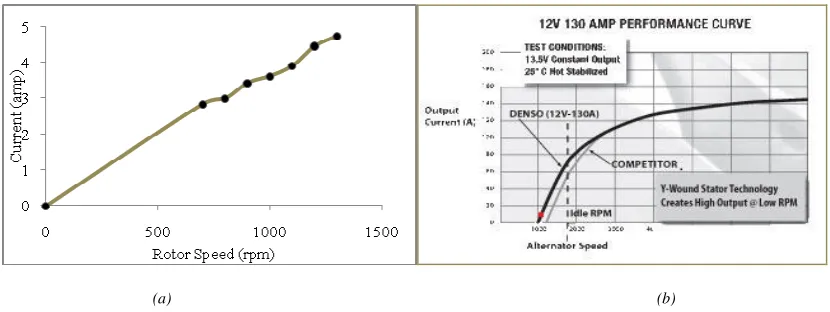
(a) (b)
Figure.4. (a)Charging current Vs Rotor Speed; (b) performance curve of a typical alternator
Power obtained by a single person and two persons are given below.
Table 3. Power output for single person and two person
Output Power (Watt) Single Person
Output Power (Watt) Two person
43.57 58.9
25.24 45.4
27.94 41.1
25.50 39.7
26.88 38.1
28.05 39.6
25.54 39.2
26.80 39.5
29.55 38.3
IV. COMPARISON WITH SOLAR PANEL
Table 4. Cost analysis
Components Price (USD)
Structure
Frame 15
Axle 10
Pulleys, sprockets and chains 12
Angle Bar (17.5 kg) 15
Accessories 10
Alternator 35
Battery 30
Total $ 127
Table 5. cost comparison
Power Source Cost (USD) Per watt Solar Energy 7.79
V. DISCUSSION AND CONCLUSION
Human power generation can be an attractive renewable source as far as small-scale production of electricity is concerned. Although, initially it may not be popular to city-dwellers where electricity is available at a much cheaper rate and consumption is huge, the prospect of using human power generation in rural areas is brighter, where electricity is scarce and often completely unavailable. This system can, under such circumstances, help produce enough electricity for lighting individual homes at a village. Also, the concept of multiple pedaling can reduce the physical effort needed and charging time, which are vital in rural areas where agrarian life often demands human energy for other uses, such as farming. Other fields of application of this pedal-powered generator may include supplying necessary amount of electricity during long term load-shedding, charging small electronic equipments and so on. Another interesting use can be powering and charging portable research equipments in isolated and inhospitable places, such as in the arctic region or the jungle. In that case, the design needs to be adapted for portability, since the current design is quite bulky. The preliminary studies on the paddle power generator are encouraging as the system has a low cost when compared to a solar photovoltaic home system of similar energy output. Also materials needed to make the setup are available and fabrication is quite simple; maintenance required is therefore low.
REFERENCES