e-ISSN: 2278-7461, p-ISSN: 2319-6491
Volume 8, Issue 4 [April 2019] PP: 33-42
Review of the Atmospheric Channel in FSO Communication
System
Jeremiah Oluwatosin Bandele
Department of Electrical, Electronics and Computer Engineering, College of Engineering, Afe Babalola University, Ado-Ekiti, Ekiti State, Nigeria, P.M.B 5454
Corresponding Author: Jeremiah Oluwatosin Bandele
ABSTRACT: This paper reviews the atmospheric channel and begins by providing a general description of the atmospheric channel with particular emphasis on the various impairments that adversely affect the transmitted optical signal. The attenuation due to beam spreading, absorption, scattering, pointing and coupling loss are discussed in this paper. An overview of atmospheric turbulence (and how it leads to scintillation) is provided and various probabilistic scintillation models used in describing the turbulent channel are reviewed. The use of Monte Carlo (MC) simulation methods for atmospheric turbulence modelling is discussed. Some of the turbulence mitigation methods already proposed in literature such as aperture averaging, maximum likelihood sequence detector (MLSD) and spatial diversity were also reviewed in this paper.
KEYWORDS: Atmosphericturbulence,beam spreading, absorption, scattering, Monte Carlo simulation
--- Date of Submission: 01-01-2020 Date of acceptance: 16-01-2020 ---
I.
INTRODUCTION
The optical signal propagated through the atmospheric channel is usually attenuated due to its susceptibility to various impairments [1]. Line-of-sight (LOS) impairments such as physical obstructions along the propagation path can be reduced (or eliminated) by correctly positioning the transmitter and receiver. However, impairments dependent on the geographic location and time such as fog, rain, snow, haze and atmospheric suspended particles (mainly concentrated near the earth surface) such as aerosols and gases presents a greater challenge [2-4]. These impairments result in scattering (i.e. directional change in the transmitted signal due to suspended particles) and absorption (i.e. conversion of photon to heat after colliding with atmospheric molecules such as nitrogen, oxygen, argon and carbon dioxide). Absorption is mainly wavelength dependent and its effect can be mitigated by choosing an appropriate wavelength for the transmitted signal. Also, scattering (which makes the most contribution to the atmospheric attenuation factor) can be classified (based on the suspended particles radius and wavelength) into three different types namely Rayleigh, Mie and non-selective (described with geometric optics) scattering [2, 3, 5].
A major impairment to seamless signal transmission through the atmosphere is thermal inhomogeneity. These thermal inhomogenities cause random temporal and spatial refractive index changes which results in large-scale and small-scale eddies (i.e. atmospheric turbulence) that haphazardly interacts with the transmitted optical signal [1, 6]. Atmospheric turbulence causes scintillation (i.e. optical signal power fluctuation) and it significantly affects system performance [1, 7]. The effect of atmospheric turbulence becomes even more severe in long distance communication [5, 8]. It is essential that system designers understand the various impairments in the atmospheric channel so that adequate penalties can be incorporated where required.
II.
ATMOSPHERIC TURBULENCE
The earth surface consists of various packets of air varying in size and temperature [1]. This inhomogeneity in the thermal state of the atmosphere causes refractive index changes (mainly due to temperature fluctuations [6]) referred to as optical turbulence [9-11]. An approximation of the refractive index can be given as [6].
K Tmbar p
nm
n177.610617.52103
2 atm (1)where patm and T represents the atmospheric pressure and temperature respectively. The packets of air in the atmosphere are then further split by optical turbulence into turbulence eddies; which can be classified into inner scales
l
0 and outer scalesL
0 depending on their sizes (shown in Fig. 1) [3, 6, 12]. Typically sizes of0
between the outer and inner scale [3]) is given as [3, 6]
2 113 0 01 1
; 033
.
0 Cn L l
n
(2)
where Cn2 represents the refractive index structure parameter and k2
represents the optical wave number where
represents the optical wavelength. Since the Kolmogorov spectrum model is only limited to the inertia subrange, other models have been derived to cover the outer and inner scales. For instance, the spectrum model originally developed by Novikov [6] for velocity fluctuations but later adapted by Tatarskii [6] for refractive index random fluctuations in both the inertia and dissipation ranges (eddies with sizes smaller than the inner scale) is given as [3, 6]
0 02 2 3
11 2
92 . 5 ;
1 ;
exp 033
.
0 C l m l
m n
n
(3)While another spectrum model (that incorporates the outer scale) was developed by Andrew as shown in [6], it is noteworthy that free-space optical (FSO) links are mainly affected by the energy of eddies in the inertia subrange [6]. The atmospheric turbulence strength (i.e. scintillation magnitude) can be described by a scintillation index given as [12]
2 2 2 2
I I I
l
(4)
where I and I represents the optical signal irradiance and average irradiance respectively. The effect of atmospheric turbulence is more significant when a point receiver is used due to the varying degree of beam intensity [6].
Fig. 1: Diagrammatic representation of a fluctuating signal due to the atmospheric turbulence [1].
2.1 Probabilistic Scintillation Models
Various statistical models (representing the randomly varying signal intensity) have been used to describe atmospheric-induced turbulence fading [12]. The lognormal distribution is commonly used to characterise the weak turbulence regime [9, 13] and the K distribution (which is consistent with experimental results [14]) is used to characterise the strong turbulence regime [15, 16]. Compared to the lognormal distribution, the gamma-gamma distribution used to characterise the weak to strong turbulence regimes [17, 18] shows better agreement between experimental and theoretical data [6, 14]. In a saturated turbulence regime, the negative exponential distribution has proved to give a better fit when compared with theoretical data [19]. Note that a plane wave assumption is made for the received optical waves.
2.1.1 Lognormal Turbulence Model
; 0 2 2 1 ln exp 2 1 , 2 2 2 2 I I I I I I f l l lLNI
(5)
It is computationally convenient to define a paramater
h
, which can be used to describe the varying channel loss or gain due to atmospheric turbulence.h
has a mean value of 1, and in the turbulent free limit, this mean value is attained at all times. Withh
I
I
and by transforming random variables (i.e.
I dI f dh
hfLNI LNh ), the lognormal PDF is given with respect to
h
as
; 02 2 1 ln exp 2 1 2 2 2 2 h h h h f l l l
LNh
(6)
where the variance of the natural logarithm of the irradiance (i.e. the scintillation index given in (3.4)) can be obtained as [1]
169 . 0 1 51 . 0 11 . 1 1 49 . 0 exp 6 5 5 12 2 6 7 5 12 2 2 R R R R l
(7)where R2, the Rytov variance used to characterise the different turbulence regimes is given as [12] 6
11 6 7 2
2 1.23C k D
n R
(8)
Note that the weak, moderate, strong andsaturated turbulence regimes can be described by R2 1,
1 ~ 2
R
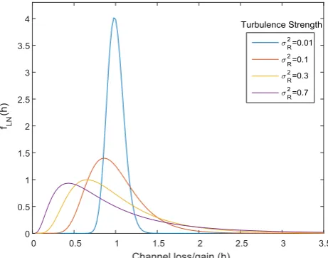
, R2 1and R2 respectively [7]. Even though the Rytov variance can be used to describe the different turbulence levels for the lognormal distribution, experimental results have shown that the lognormal approximation is only valid for the weak turbulence regime because at higher turbulence levels, the multiple scattering experienced is not accounted for in the Rytov approximation [1]. The lognormal PDF is shown in Fig. 2 for different Rytov variance values. In Fig. 2, it is observed that as the turbulence level increases, the PDF becomes more skewed to the left with longer tails to the right. This shows how much the channel inhomogeneity has adversely affected the irradiance fluctuation.
Fig. 2: Lognormal PDFs against
h
for different Rytov variance values. 2.1.2 Gamma-Gamma Turbulence ModelThe fluctuations experienced by an optical signal propagating through a turbulent atmosphere consists of small-scale and large-scale effects. The small-scale effects (scattering) are caused by eddies smaller than
by eddies larger than the Fresnel zone or the scattering disk
D
k
p
0[20]. Thus, the unconditionalgamma-gamma PDF (which is obtained from the contributions of the small-scale and large-scale effects) can be given as [14, 17, 18, 20]
,
2
2 ; 0;1 2 2 I I I K I I I I f I
GG
(9)
where
and are the number of large and small scale eddies due to the scattering processrespectively,
. is the Gamma function and Ku
. is the modified Bessel function of the second kind withorder,
u
. The unconditional gamma-gamma PDF is obtained with respect toh
as
2
2
; 0;1 2 2 h h K h h f h
GG
(10)
where the parameters
and are defined as [7, 20]
1 6 7 5 12 2 1 11 . 1 1 49 . 0 exp R R (11)
1 6 5 5 12 2 1 69 . 0 1 51 . 0 exp R R (12)
The gamma-gamma PDF is shown in Fig. 3 for the weak, moderate and strong turbulence regimes. Fig. 3 shows that as the turbulence strength increases, the PDF spreads out more. As earlier stated, the gamma-gamma distribution, which shows excellent agreement between experimental and theoretical data when used to characterise the weak to strong turbulence regimes is preferred for turbulence modelling in many applications [6, 14]. Also, it can be observed in Fig. 3 that as
1 (stronger turbulence), the gamma-gamma distribution tends towards a K distribution.Fig. 3: Gamma-gamma PDFs against
h
for different turbulence strengths. 2.1.3 K Turbulence ModelThe K distribution (arising from two independent distributions; the negative exponential and gamma distributions) is widely accepted for modelling the strong atmospheric turbulence regime because it gives a good agreement with experimental data [14, 15]. The unconditional PDF of the K distribution is given as [14-16]
,
2
1 2 ; 0;2 1 I I I K I I I I
fKI
(13)
2
2 1
2 ; 0; 1
h h
K h h
f
h
K
(14)
The K PDF is shown in Fig. 4 where the PDF right hand tail spreads out more and the peak decreases
as the turbulence strength increases. Note that as
R
, the K distribution tends towards a negative exponential distribution.Fig. 4: K PDFs against
h
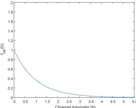
for different strong turbulence values. 2.1.4 Negative Exponential Turbulence ModelFor a large number of independent scattering and propagation paths spanning several kilometres, the optical signal experiences very strong irradiance fluctuation and the turbulence regime is known as the saturated (i.e. fully developed speckle [19]) regime [7, 21]. Theoretical and experimental verifications have proved that negative exponential statistics are suitable for modelling the saturated turbulence regime [19]. The PDF of the negative exponential is given by [6, 19]
,
1 exp ; 0;
I
I I I
I I f
I
NE (15)
Also, the negative exponential PDF is obtained with respect to
h
as
h exp
h; I0;fNEh (16)
The negative exponential PDF is shown in Fig. 5. As expected, the PDF is similar to those obtained with the gamma-gamma and K distributions at very strong turbulence regimes.
In addition to the turbulence models mentioned above, the weak to strong turbulence regime can be modelled with the I-K and lognormal-Rician distributions. Note that the K, lognormal-Rician, I-K and gamma-gamma turbulence models all tends towards the negative exponential turbulence model in very strong to saturated turbulent regimes [19].
III.
ATTENUATION DUE TO BEAM SPREAD AND THE ATMOSPHERIC CHANNEL
Beam spreading is a distance dependent impairment which refers to an increment in the transmitted beam divergence angle as it propagates the atmosphere thereby reducing the amount of radiation captured by the receiver (shown in Fig. 6) [2, 22]. With assumptions that no obstructions exist between the transmitter and the receiver, that the transmitted power has a uniform distribution and that the transmitter diameter is very small, the loss due to beam spread in an FSO link can be given as [22-24]
2
bD rx bs
d d
L (17)
where drx represents the receiver diameter and dbD
D represents the beam diameter due todiffraction alone where and D represents the beam divergence angle and propagation distance respectively.
The attenuation experienced by the optical signal as it propagates through the atmosphere is dependent on the channel visibility and varies with time. The atmospheric attenuation is given by the Beer-Lambert’s law as [2, 25]
D
Latmexp (18)
where
(a function of scattering and absorption) represents the atmospheric attenuation factor. With the impact of absorption largely negligible,
(assuming the Mie scattering model) is given as [2]
nm
V 550
91 . 3
(19)
where
V
,
and
represents the atmospheric visibility (the longest horizontal atmospheric distance through which an object is visible), operating wavelength of the laser source and a parameter (values given by the kim [26] and kruse [27] models) related to visibility and distribution of particle size in the propagation path respectively.Fig. 6: Diagrammatic representation of an FSO link.
IV.
ATTENUATION DUE TO POINTING AND COUPLING LOSSES
misdirected such that it essentially misses the receiver completely. Pointing loss has a detrimental effect on system performance. However, with increased implementation cost, responsive tracking systems can be used to automatically align the transmitter with the receiver thereby mitigating the effect of pointing error [2, 28-30].
Under the assumptions that the received beam is Gaussian, the receiver aperture is circular and the radial displacement from the beam centre axis r follows a Raleigh distribution model, the probability density distribution of the attenuation due to pointing error and beam spreading is given as [28, 30, 31]
01
0 2
0 ;
2
2 h h a
a h
fhp p p p
(20)
where s
eq
w
2 , s represents the standard deviation of the pointing loss displacement at the receiver,e q
w represents the equivalent beam width,
a
0 represents the fraction of the power collected by the receiving lens and hp represents attenuation due to pointing error and beam spreading.When fibre components are integrated into FSO links (i.e. systems with optical amplifiers (OAs) and wavelength-division multiplexing (WDM) networks), loss occurs as the optical signal is coupled into the fibre. The coupling loss is largely due to a turbulence-induced reduction in the atmospheric coherence length and while adaptive optics can be used to mitigate its effect, it is customary to include a coupling loss penalty in the link budget [7, 23, 24, 32].
V.
MODELLING OF SYSTEM PARAMETERS UNDER ATMOSPHERIC TURBULENCE
CONDITIONS WITH MONTE CARLO SIMULATION METHODS
MC simulation (also known as statistical sampling) is a computational technique used to obtain numerical results by repetitive random sampling. It is particularly useful in applications where it is either too complicated or impossible to use other mathematical methods [33]. Due to the random effect of atmospheric turbulence which, in some cases, overstretches analytical methods when used, MC simulation methods are used in several aspects of this work. The MC simulation technique (flowchart shown in Fig. 7) involves the generation of random numbers that follows pre-defined turbulence distributions. To generate a sample random
variable of a particular turbulence distribution, a uniform random variable (i.e.
U
0
,
1
) can be used to give a value for the cumulative distribution function (CDF) of the turbulence distribution, which is mapped to the appropriate argument and thus directly samples the desired input PDF. By performing repetitive sampling, a histogram approximating to the PDF corresponding to the particular turbulence distribution and more particularly, functions of its samples can be obtained for different system parameters. The system parameters are then used to analyse system performance. This approach is particularly computationally convenient and useful in cascaded FSO links.VI.
SCINTILLATION MITIGATION TECHNIQUES
Some of the methods already proposed in literature for scintillation mitigation are summarised below
1) Aperture averaging: This technique involves making the receiver aperture size bigger than the correlation length of the intensity fluctuation such that the signal fluctuations are averaged over the receiver aperture size [1, 12]. While aperture averaging has been shown to be effective (even in strong turbulence [34]), it is sometimes expensive or impractical to make the aperture size bigger than the correlation length of the intensity fluctuation [35, 36].
2) Spatial diversity: This technique ensures that multiple faded versions of the same signal are collected at the receiving end. In order to prevent correlated fading (and ensure improved system performance [36]), the spatial separation between the transmitting and/or receiving lenses should be made bigger than the coherence length of the intensity fluctuation [37]. Spatial diversity can be realised either as multiple transmitters sending signals to multiple receivers (MIMO), multiple transmitters sending signals to a single receiver (MISO) or a single transmitter sending signals to multiple receivers (SIMO) [9, 15]. The practical realization of a spatially diverse system is costly due to the multiple transmitters/receivers required and difficult to implement because of the transmitter and receiver alignment requirements [36].
3) Maximum likelihood sequence detector (MLSD): This technique jointly detects multiple symbols depending on the statistical and temporal characteristics of the channel [38]. MLSD has been analysed for instances where channel state information (CSI) is known and when it’s not known [38, 39]. Even though MLSD has been shown to efficiently mitigate scintillation, its complicated operation (i.e. performing multidimensional integration) makes it less attractive [35].
4) Forward error correction (FEC) with interleaving: The FEC technique involves the addition of error correcting codes to the transmitted information. If the errors in the received signal are minimal, FEC can easily be used to recover the original transmitted information. However, for burst errors (possible in FSO communication systems due to atmospheric turbulence), FEC becomes less efficient for information recovery. Using interleaving with FEC is beneficial in a turbulent atmosphere. Interleaving involves a reshuffling process (which reduces the effect of burst errors) at the transmitting and receiving ends such that the recovery performance of FEC is improved even when burst errors occur [40, 41].
5) Cooperative diversity and multi-hop transmission: This technique involves the introduction of relays nodes in-between the transmitter and receiver. The configuration of the relay nodes could be serial (i.e. multi-hop) or parallel (i.e. cooperative diversity) [42]. The relaying method can be further characterised based on their mode of operation as shown below.
I. Amplify-and-forward (AF): At each relay node, the received optical signal is first normalized to unity after which the relay modulates the signal with the transmitter power. The signal is then retransmitted to another relay or the receiver. This method ensures that, at each relay point, the optical signal is transmitted with the same power as the transmitter power [25, 42, 43].
II. Decode-and-forward (DF): At each relay node, the received optical signal is decoded and directly modulated with the transmitter power. The signal is then retransmitted to another relay or the receiver. This process only takes place if the received signal-to-noise ratio exceeds a pre-determined decoding threshold [42, 44, 45].
gains to lower input powers) with the assumption that the gain dynamics is faster relative to atmospheric turbulence [46-48]. This method will form part of the focus of the present work.
VII.
CONCLUSION
This paper reviewed the atmospheric channel through which the transmitted optical signal propagates. Impairments such as obstacles along the propagation path, absorption, scattering and atmospheric turbulence were discussed. Various models used to characterise the turbulent channel were reviewed. The lognormal turbulence model is known to be valid in the weak turbulence regime and the gamma-gamma turbulence model (which covers the weak to strong turbulence regime) gives results that are similar to experimental results. The K and negative exponential turbulence model are suitable for the strong and saturated turbulence regimes respectively. The impact of the attenuation due to beam spreading, atmospheric channel, pointing and coupling losses on the transmitted optical signal were discussed in this paper. The use of MC simulation techniques for modelling atmospheric turbulence was discussed and some turbulence mitigation methods were examined.
REFERENCES
[1]. Z. Ghassemlooy, W. O. Popoola, and S. Rajbhandari, Optical Wireless Communications: System and Channel Modelling with MATLAB. Boca Raton, FL 33487-2742: CRC Press, 2012.
[2]. Z. Ghassemlooy and W. Popoola, "Terrestrial Free-Space Optical Communications," in Mobile and Wireless Communications: Network layer and circuit level design, ed: INTECH, 2010, pp. 355-394.
[3]. J. C. Ricklin, S. M. Hammel, F. D. Eaton, and S. L. Lachinova, "Atmospheric channel effects on free-space laser communication," Journal of Optical and Fiber Communications Reports, vol. 3, pp. 111-158, 2006.
[4]. T. Singh, "Calculations of the impact on atmospheric turbulence conditions on free space optical communication links using gamma-gamma model," in 4th International Conference on Computing, Communications and Networking Technologies (ICCCNT), 2013, pp. 1-5.
[5]. A. C. Motlagh, V. Ahmadi, Z. Ghassemlooy, and K. Abedi, "The effect of atmospheric turbulence on the performance of the free space optical communications," in 6th International Symposium on Communication Systems, Networks and Digital Signal Processing (CNSDSP), 2008, pp. 540-543.
[6]. L. C. Andrews and R. L. Phillips, Laser Beam Propagation Through Random Media vol. 52. Bellingham, WA: SPIE press, 2005. [7]. A. O. Aladeloba, A. J. Phillips, and M. S. Woolfson, "Improved bit error rate evaluation for optically pre-amplified free-space
optical communication systems in turbulent atmosphere," IET Optoelectronics, vol. 6, pp. 26-33, 2012.
[8]. Z. Xiaoming and J. M. Kahn, "Free-space optical communication through atmospheric turbulence channels," IEEE Transactions on Communications, vol. 50, pp. 1293-1300, 2002.
[9]. S. M. Navidpour, M. Uysal, and M. Kavehrad, "BER Performance of Free-Space Optical Transmission with Spatial Diversity," IEEE Transactions on Wireless Communications, vol. 6, pp. 2813-2819, 2007.
[10]. H. G. Sandalidis, T. A. Tsiftsis, G. K. Karagiannidis, and M. Uysal, "BER performance of FSO links over strong atmospheric turbulence channels with pointing errors," IEEE Communications Letters, vol. 12, pp. 44-46, 2008.
[11]. W. O. Popoola, Z. Ghassemlooy, J. I. H. Allen, E. Leitgeb, and S. Gao, "Free-space optical communication employing subcarrier modulation and spatial diversity in atmospheric turbulence channel," IET Optoelectronics, vol. 2, pp. 16-23, 2008.
[12]. A. K. Majumdar, "Free-space laser communication performance in the atmospheric channel," Journal of Optical and Fiber Communications Reports, vol. 2, pp. 345-396, 2005/10/01 2005.
[13]. M. Abaza, R. Mesleh, A. Mansour, and E. H. M. Aggoune, "Spatial diversity for FSO communication systems over atmospheric turbulence channels," in IEEE Wireless Communications and Networking Conference (WCNC), 2014, pp. 382-387.
[14]. M. A. Al-Habash, L. C. Andrews, and R. L. Phillips, "Mathematical model for the irradiance probability density function of a laser beam propagating through turbulent media," Optical Engineering, vol. 40, pp. 1554-1562, 2001.
[15]. T. A. Tsiftsis, H. G. Sandalidis, G. K. Karagiannidis, and M. Uysal, "FSO Links with Spatial Diversity over Strong Atmospheric Turbulence Channels," in IEEE International Conference on Communications (ICC), 2008, pp. 5379-5384.
[16]. M. Uysal and J. Li, "BER performance of coded free-space optical links over strong turbulence channels," in IEEE 59th Vehicular Technology Conference (VTC), 2004, pp. 352-356 Vol.1.
[17]. P. Liu, X. Wu, K. Wakamori, T. D. Pham, M. S. Alam, and M. Matsumoto, "Bit error rate performance analysis of optical CDMA time-diversity links over gamma-gamma atmospheric turbulence channels," in IEEE Wireless Communications and Networking Conference, 2011, pp. 1932-1936.
[18]. P. V. Trinh, A. T. Pham, H. T. T. Pham, and N. T. Dang, "BER analysis of all-optical AF dual-hop FSO systems over Gamma-Gamma channels," in IEEE 4th International Conference on Photonics (ICP), 2013, pp. 175-177.
[19]. W. O. Popoola, Z. Ghassemlooy, and E. Leitgeb, "BER performance of DPSK subcarrier modulated free space optics in fully developed speckle," in 6th International Symposium on Communication Systems, Networks and Digital Signal Processing (CNSDSP), 2008, pp. 273-277.
[20]. Z. Ghassemlooy, W. O. Popoola, and E. Leitgeb, "Free-Space Optical Communication Using Subcarrier Modulation in Gamma-Gamma Atmospheric Turbulence," in 9th International Conference on Transparent Optical Networks (ICTON), 2007, pp. 156-160. [21]. W. O. Popoola, Z. Ghassemlooy, and V. Ahmadi, "Performance of sub-carrier modulated Free-Space Optical communication link in
negative exponential atmospheric turbulence environment," International Journal of Autonomous and Adaptive Communications Systems, vol. 1, pp. 342-355, 01/01/ 2008.
[22]. S. Bloom, E. Korevaar, J. Schuster, and H. Willebrand, "Understanding the performance of free-space optics [Invited]," Journal of Optical Networking, vol. 2, pp. 178-200, 2003.
[23]. A. M. Mbah, J. G. Walker, and A. J. Phillips, "Performance evaluation of turbulence-accentuated interchannel crosstalk for hybrid fibre and free-space optical wavelength-division-multiplexing systems using digital pulse-position modulation," IET Optoelectronics, vol. 10, pp. 11-20, 2016.
[24]. A. O. Aladeloba, M. S. Woolfson, and A. J. Phillips, "WDM FSO network with turbulence-accentuated interchannel crosstalk," IEEE/OSA Journal of Optical Communications and Networking, vol. 5, pp. 641-651, 2013.
[26]. I. I. Kim, B. McArthur, and E. Korevaar, "Comparison of laser beam propagation at 785 nm and 1550 nm in fog and haze for optical wireless communications," in proc. SPIE, 2001, pp. 26-37.
[27]. P. W. Kruse, L. D. McGlauchlin, and R. B. McQuistan, Elements of infrared technology: generation, transmission, and detection: Wiley, 1962.
[28]. J. Park, E. Lee, C.-B. Chae, and G. Yoon, "Impact of Pointing Errors on the Performance of Coherent Free-Space Optical Systems," IEEE Photonics Technology Letters, vol. 28, pp. 181-184, 2016.
[29]. K. P. Peppas, A. N. Stassinakis, H. E. Nistazakis, and G. S. Tombras, "Capacity analysis of dual amplify-and-forward relayed free-space optical communication systems over turbulence channels with pointing errors," Journal of Optical Communications and Networking, vol. 5, pp. 1032-1042, 2013.
[30]. P. M. I. and D. G. T., "Effects of pointing errors on average capacity of FSO links over gamma-gamma turbulence channel," in 11th International Conference on Telecommunication in Modern Satellite, Cable and Broadcasting Services (TELSIKS), 2013, pp. 481-484.
[31]. A. O. Aladeloba, A. J. Phillips, and M. S. Woolfson, "DPPM FSO communication systems impaired by turbulence, pointing error and ASE noise," in 14th International Conference on Transparent Optical Networks (ICTON), 2012, pp. 1-4.
[32]. X. Zhao, H. Jiang, and H. Zheng, "Fiber coupling efficiency through turbulence medium for long and short exposures," in International Conference on Optoelectronics and Microelectronics (ICOM), 2012, pp. 334-336.
[33]. N. Metropolis, "The beginning of the Monte Carlo method," Los Alamos Science, vol. 15, pp. 125-130, 1987.
[34]. J. H. Churnside, "Aperture averaging of optical scintillations in the turbulent atmosphere," Applied Optics, vol. 30, pp. 1982-1994, 1991.
[35]. Z. Xiaoming and J. M. Kahn, "Markov chain model in maximum-likelihood sequence detection for free-space optical communication through atmospheric turbulence channels," IEEE Transactions on Communications, vol. 51, pp. 509-516, 2003. [36]. A. K. Majumdar, Advanced Free Space Optics (FSO): A Systems Approach: Springer New York, 2014.
[37]. G. L. Stüber, Principles of Mobile Communication. U.S.A. : Kluwer Academic Publishers, 2012.
[38]. N. D. Chatzidiamantis, G. K. Karagiannidis, and M. Uysal, "Generalized Maximum-Likelihood Sequence Detection for Photon-Counting Free Space Optical Systems," IEEE Transactions on Communications, vol. 58, pp. 3381-3385, 2010.
[39]. M. L. B. Riediger, R. Schober, and L. Lampe, "Multiple-symbol detection for photon-counting MIMO free-space optical communications," IEEE Transactions on Wireless Communications, vol. 7, pp. 5369-5379, 2008.
[40]. T. Ming-Fong, K. Chih-Heng, L. Hao-Ming, and H. Hsiung-Yu, "Forward Error Correction with Interleaving mechanism combining Cognitive Technology for video streaming over wireless networks," in Wireless and Pervasive Computing (ISWPC), 2011 6th International Symposium on, 2011, pp. 1-6.
[41]. Z. Xiaoming and J. M. Kahn, "Performance bounds for coded free-space optical communications through atmospheric turbulence channels," IEEE Transactions on Communications, vol. 51, pp. 1233-1239, 2003.
[42]. M. Safari and M. Uysal, "Relay-assisted free-space optical communication," IEEE Transactions on Wireless Communications, vol. 7, pp. 5441-5449, 2008.
[43]. T. A. Tsiftsis, H. G. Sandalidis, G. K. Karagiannidis, and N. C. Sagias, "Multihop Free-Space Optical Communications Over Strong Turbulence Channels," in IEEE International Conference on Communications (ICC), 2006, pp. 2755-2759.
[44]. M. Safari and M. Uysal, "Diversity gain analysis of free-space optical communication systems," in Canadian Conference on Electrical and Computer Engineering (CCECE ), 2008, pp. 001239-001244.
[45]. Y. Jiao, J.-B. Wang, X. Dang, M. Chen, W. Hu, and Y.-H. Huang, "Performance analysis of multi-hop free space optical communications with pointing errors," in 9th International Conference on Optical Communications and Networks (ICOCN), 2010, pp. 290-293.
[46]. K. Yiannopoulos, N. C. Sagias, and A. C. Boucouvalas, "Fade Mitigation Based on Semiconductor Optical Amplifiers," Journal of Lightwave Technology, vol. 31, pp. 3621-3630, 2013.
[47]. A. C. Boucouvalas, N. C. Sagias, and K. Yiannopoulos, "First order statistics of semiconductor optical amplifier assisted optical wireless systems under log-normal fading," in 2nd International Workshop on Optical Wireless Communications (IWOW), 2013, pp. 142-146.
[48]. M. Abtahi, P. Lemieux, W. Mathlouthi, and L. A. Rusch, "Suppression of Turbulence-Induced Scintillation in Free-Space Optical Communication Systems Using Saturated Optical Amplifiers," Journal of Lightwave Technology, , vol. 24, pp. 4966-4973, 2006.