e-ISSN: 2278-067X, p-ISSN: 2278-800X, www.ijerd.com Volume 6, Issue 9 (April 2013), PP. 15-24
Performance Improvement of Low Power Wind-Driven
Wound Rotor Induction Generators with Combined Input
Voltage and Slip Power Control
M. Munawar Shees
1,2, A. F. Almarshoud
2, M. S. Jamil Asghar
31
Singhania University, Jhunjhunu, Rajasthan, India 2
College of Engineering, Qassim University, Buraidah, K.S.A. 3
Electrical Engineering Department, Aligarh Muslim University, Aligarh, U.P., India
Abstract:- Various techniques have been employed to optimize the performance of wound rotor induction generator (WRIG) based wind power generation systems. Input voltage control was used for the improvement of power factor in grid-connected induction generators. However, in this case, efficiency reduces drastically due to high output current. Moreover, the control range is limited. The conventional rotor resistance control had also been used for wind-driven WRIG. But, with this, the input power factor becomes very poor. In this paper, a new control method is proposed where both input voltage and slip power control are combined to achieve better performance. For each operating point an optimum input voltage is set and slip is controlled by rotor resistance such that the maximum efficiency is obtained. Moreover, both power factor and efficiency are improved for a wide range of speed variations. Also the reactive power demand is reduced throughout the range of effective speed which is compensated by optimum fixed capacitors. This scheme is useful for low power wind energy conversion system (WECS) where wind speed varies over wide range. Simulation model for the proposed schemes are developed using MATLAB and the performance of the induction generator under various wind conditions are studied with this model. Also the performance characteristics of the proposed schemes are experimentally verified. The proposed control schemes are simple as well as cheap.
Index Terms:- Combined input voltage and slip power control, Wound Rotor Induction generator (WRIG), MATLAB, Slip power control, Renewable energy sources (RES), Wind energy conversion system (WECS).
I. INTRODUCTION The increasing energy demand throughout the world, the air pollution produced by burning of fossil fuels as well as the depletion of fossil fuels and the growing doubt about the safety of nuclear power led to a growing demand for the wider use of renewable energy sources (RES). Wind power is one among the leading renewable energy sources, which can overcome the concern of energy shortage in future. Wind power has proven to be a potential clean renewable source for generation of electricity with minimal environmental impact. This has a great impetus for interest in the wind energy conversion system (WECS) as potential power source. With the priority status accorded to it in many countries, the share of wind power in relation to overall installed capacity has increased significantly, while in some of the countries, it is approaching to 50% mark [1]. The wind energy will be able to contribute at least 12% of global electricity consumption by the year 2020 [2].
Grid-connected induction generators have many advantages over synchronous generators. It does not require separate field circuit. A controlled synchronization with grid is not required. The ac line regulates the frequency and output voltage of the induction generator, eliminating the need for expensive and complex electronic conversion equipment. Moreover, it is not necessarily to be operated at fixed speed as in case of synchronous generator. The operating speed of the induction generator is self-adjustable according to the variation in the input torque. This also reduces the wear and tear on the gearbox [3,4]. When input torque increases beyond push-over torque, power generation starts and machine speed increases. The main demerit is, it requires reactive (lagging) power, which is to be supplied externally (e.g. by capacitor bank)[4].
especially at low wind speeds. The conventional rotor resistance control had been used with WRIG for wind power generation. But, the main demerit of this system is its very low input power factor. Moreover, the efficiency also becomes poor [6]. Often, an ac voltage regulator is used for soft switching to reduce the extra wear on the gearbox at the time of cut-in of the generator. The voltage control by an ac voltage regulator had been suggested earlier to improve the power factor. However, in this case the efficiency drops drastically and control range is also limited [7,8]. Moreover, the total harmonic distortion (THD) also increases with the increase of triggering angle or at low output voltage [9].
Most of the doubly-fed induction generators (DFIG) and synchronous generators, incorporate sophisticated power electronic control systems. However, DFIG is capable to control both active and reactive power independently [10]. The dynamic voltage restorer is also used for active and reactive power control for wind turbine based power generation system [11].
To optimize the performance of wind power generation various techniques have been employed. The dual stator-winding induction generator with static excitation controller is one among the various optimum schemes [12]. Recently the performance of wound-rotor induction motor had been greatly enhanced by the combination of input voltage control and slip power control [13]. In this paper this technique is extended for wind-driven WRIGs to improve both efficiency and power factor, over a wide range of speed. Moreover, another scheme is also proposed in which fixed capacitors are connected in parallel with the rotor external resistances to compensate the reactive power demand of the induction generator. Therefore no separate control of reactive power is needed. Here, the induction generator is made to operate at its optimum point, therefore optimum performance is achieved. A comparison of the proposed schemes with conventional rotor resistance control scheme is also presented.
II. CONVENTIONALSLIPPOWERCONTROLSCHEME
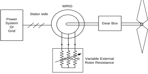
In the conventional slip power control scheme using rotor resistance control method, the speed of the induction machine is controlled by varying the external resistance, which is inserted in the rotor circuit. Figure 1 shows the slip power control scheme for wound rotor induction generator. However, in this type of control, there is substantial loss in the external resistors at higher speeds which reduces the overall efficiency of the system [14]. The torque-speed characteristic of a wound rotor induction generator (WRIG) with slip power control is shown in Fig. 2. It also indicates the different operating points of WRIG under different wind speeds.
Power System Or Grid
R R
R
Gear Box Stator side
Variable External Rotor Resistance WRIG
Fig. 1 : Slip power control scheme of a wound rotor induction generator
Speed
T
o
rq
u
e
Wind turbine characteristics for optimum power
Ns 2 Ns
Tmax
- Tmax
Low Efficiency Region of Induction Generator
III. PROPOSEDSCHEME
In the proposed scheme, the characteristic of WRIG is matched with the characteristic of a wind turbine using combined input voltage and slip power control. Figure 3 shows the circuit topology of the proposed scheme. Here, the slip power controller circuit controls the power in the rotor circuit by varying the external resistance in the rotor circuit. The input voltage is controlled by using an auto transformer or an ac voltage regulator. For a particular wind speed, a particular regulated input ac voltage is applied to the stator of WRIG and a fixed external resistance is put in the rotor circuit such that characteristics of WRIG and wind turbine are matched as shown in Fig. 4. Here, the maximum torque of WRIG matches with the available optimum torque of the wind. Moreover, the efficiency of an induction machine is maximum when the machine is operated at or near the maximum torque condition. In this way, both efficiency and power factor improve for the whole range of control.
Power System Or Grid
Gear Box WRIG
AC Regulator Or Auto-transformer
Slip Power Control Circuit
Fig. 3: Circuit topology of the proposed scheme
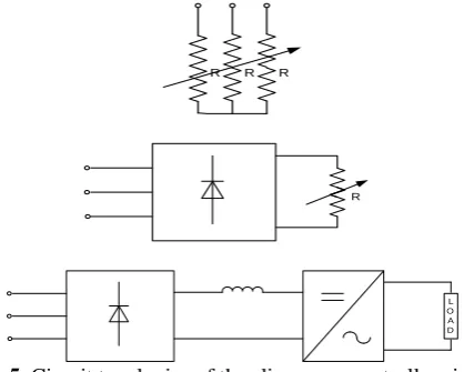
The different topologies for the slip power control circuit are shown in Fig. 5.
Speed
Ns 2 Ns
T
o
rq
u
e
Tmax1
Tmax2
Tmax3
Tmax4
Tmax1 Tmax2 Tmax3 Tmax4
Wind Turbine Characteristics for
optimum power
High Efficiency Region of Induction Generator
Fig. 4: Characteristics of a WRIG with rotor resistance as well as stator voltage control
R R
R
R
L O A D
Fig. 5: Circuit topologies of the slip power controller circuit
IV. SIMULATIONMODEL
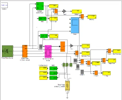
The power system is simulated with three-phase voltage source which is connected to the stator of (WRIG) asynchronous machine in SI unit (Fig. 6). The asynchronous machine is modeled in a dq-abc reference frame. The torque is applied to the WRIG as input mechanical torque „Tm‟ through a constant block. The rotor
selected from its options. Various measurement blocks such as, V-I, P-Q,V, I, T, ωm, displays, scopes etc are
placed at proper locations. For a particular torque the speed of WRIG is matched with the speed-torque characteristics of wind turbine by varying stator voltage and external rotor resistance. Under different torque conditions, the power transferred from the WRIG to grid or power system is simulated (Fig. 6). The simulated results of waveforms of stator voltage, stator current, and power fed to grid are obtained, which are shown in Fig. 7.
Fig. 6: MATLAB Simulation model of the proposed system feeding power into the grid.
0 0.01 0.02 0.03 0.04 0.05 0.06 0.07 0.08 0.09 0.1
-500 0 500
Voltage (Volts)
0 0.01 0.02 0.03 0.04 0.05 0.06 0.07 0.08 0.09 0.1
-10 0 10
Current (Amp)
0 0.01 0.02 0.03 0.04 0.05 0.06 0.07 0.08 0.09 0.1
-5000 0 5000
Time (seconds) Grid Power (Watt)
Fig. 7: Waveform showing stator voltage, stator current and power fed to grid
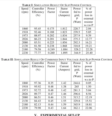
TABLE I:SIMULATION RESULT OF SLIP POWER CONTROL
Speed (rpm)
Controller Efficiency
(%)
Power Factor
Stator Current (Ampere)
Power fed to grid,
P (Watt)
% of power loss in external
resistor w.r.to P 1860 95.45 0.175 1.812 220.7 2.04 1918 92.46 0.188 1.823 239.5 5.85 1973 88.97 0.202 1.834 257.9 9.39 2026 86.23 0.201 1.844 275.3 12.77 2080 83.51 0.225 1.856 292.3 16.21 2130 81.50 0.238 1.868 310.8 19.21
2180 79.58 0.249 1.884 328.2 22.28
2230 77.77 0.260 1.895 344.9 25.40
TABLE II:SIMULATION RESULT OF COMBINED INPUT VOLTAGE AND SLIP POWER CONTROL
Speed (rpm)
Controller Efficiency
(%)
Power Factor
Stator Current (Ampere)
Power fed to grid,
P (Watt)
% of power loss in external
resistor w.r.to P
1860 97.36 0.35 1.42 244.6 0.05
1918 95.92 0.48 1.38 265 1.50
1973 92.72 0.48 1.42 281.3 5.04
2026 89.77 0.47 1.46 296.6 8.56
2080 86.51 0.46 1.51 313.2 12.19
2130 84.43 0.45 1.55 329.8 15.51
2180 82.13 0.44 1.59 345.9 18.81
2230 79.98 0.43 1.64 362.1 22.06
V. EXPERIMENTALSET-UP
A 1kW, star-connected, WRIG is mechanically coupled to a Machine Test System which consists of a Drive and Brake unit and a Control unit which can operate the machine in all the four quadrants. The stator of the induction machine is connected to a three phase ac supply through a three-phase auto-transformer and a multifunction meter which can measure active power, reactive power, power factor, frequency, voltage, current etc. Rotor is connected to a three phase variable resistor box. The D & B unit is a cradle-type three-phase asynchronous machine with integrated torque pick-up for connection to the control unit. This special machine is equipped with sufficient power and torque reserves to brake or drive a 1kW machine. The control unit is a microcontroller-controlled device with integrated frequency converter for power supply and control of the D & B unit and display of speed and torque measured values. Both the conventional slip power control scheme as well as the proposed scheme (combined input voltage and slip power control) has been experimentally tested in the laboratory.
TABLE III:EXPERIMENTAL RESULT OF SLIP POWER CONTROL
Speed (rpm)
Controller Efficiency
(%)
Power Factor
Stator Current (Ampere)
Power fed to grid, P (Watt)
% of power loss in external
resistor w.r.to P
1860 97.35 0.14 1.84 186 0.50
1918 90.71 0.15 1.86 203 7.87
1973 86.94 0.16 1.87 221 12.56
2026 83.80 0.18 1.88 241 16.79
2080 80.64 0.19 1.89 256 21.38
2130 79.09 0.20 1.91 271 22.24
2180 76.45 0.22 2.01 308 28.13
2230 74.80 0.23 2.0 323 30.97
TABLEIV:EXPERIMENTAL RESULT OF COMBINED INPUT VOLTAGE AND SLIP POWER CONTROL
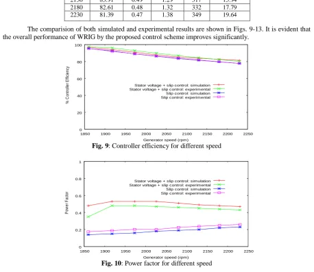
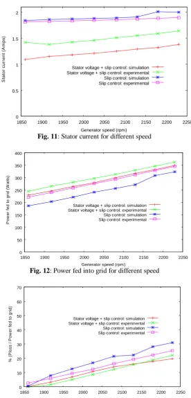
The comparision of both simulated and experimental results are shown in Figs. 9-13. It is evident that the overall performance of WRIG by the proposed control scheme improves significantly.
0 20 40 60 80 100
1850 1900 1950 2000 2050 2100 2150 2200 2250
%
C
o
n
tr
o
lle
r
E
ffi
ci
e
n
cy
Generator speed (rpm) Stator voltage + slip control: simulation Stator voltage + slip control: experimental Slip control: simulation Slip control: experimental
Fig. 9: Controller efficiency for different speed
0 0.2 0.4 0.6 0.8 1
1850 1900 1950 2000 2050 2100 2150 2200 2250
P
o
w
e
r
F
a
ct
o
r
Generator speed (rpm) Stator voltage + slip control: simulation Stator voltage + slip control: experimental Slip control: simulation Slip control: experimental
Fig. 10: Power factor for different speed Speed
(rpm)
Controller Efficiency
(%)
Power Factor
Stator Current (Ampere)
Power fed to grid, P (Watt)
% of power loss in external resistor w.r.to P
1860 96.85 0.48 1.09 229 0.24
1918 94.09 0.53 1.15 246 3.23
1973 90.94 0.53 1.18 264 6.86
2026 87.88 0.53 1.21 279 10.60
2080 85.31 0.51 1.25 299 13.98
2130 83.91 0.49 1.29 317 15.94
2180 82.61 0.48 1.32 332 17.79
0 0.5 1 1.5 2
1850 1900 1950 2000 2050 2100 2150 2200 2250
S
ta
to
r
c
u
rr
e
n
t
(A
m
p
s
)
Generator speed (rpm) Stator voltage + slip control: simulation Stator voltage + slip control: experimental Slip control: simulation Slip control: experimental
Fig. 11: Stator current for different speed
0 50 100 150 200 250 300 350 400
1850 1900 1950 2000 2050 2100 2150 2200 2250
P
o
w
e
r
fe
d
t
o
g
ri
d
(
W
a
tt
s
)
Generator speed (rpm) Stator voltage + slip control: simulation Stator voltage + slip control: experimental Slip control: simulation Slip control: experimental
Fig. 12: Power fed into grid for different speed
0 10 20 30 40 50 60 70
1850 1900 1950 2000 2050 2100 2150 2200 2250
%
(
P
lo
s
s
/
P
o
w
e
r
fe
d
t
o
g
ri
d
)
Generator speed (rpm) Stator voltage + slip control: simulation Stator voltage + slip control: experimental Slip control: simulation Slip control: experimental
Fig. 13: Percentage of power loss in the external resistor with respect to power fed to grid for different speed
VI. REACTIVEPOWERCOMPENSATION
Power System Or Grid
R R
R
Gear Box Stator side
External Rotor Resistance
WRIG
AC Regulator Or Auto-transformer
C
C C
Fig. 14 : Circuit topology of the proposed scheme with capacitor
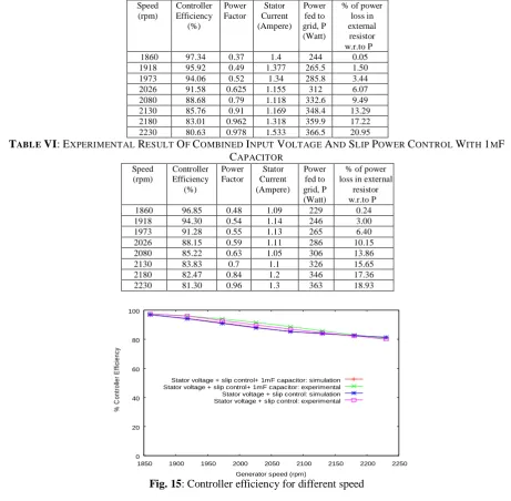
In the MATLAB simulation model of the proposed system with reactive power compensation, for the parallel RLC branch connected to the rotor of WRIG, option of RC is chosen. Then the optimum value of the capacitor is found by the simulation with trial & error method. The results obtained for an optimum value of capacitor are given in Table V. The simulation results are verified experimentally as well and tabulated in Table VI.
TABLE V:SIMULATION RESULT OF COMBINED INPUT VOLTAGE AND SLIP POWER CONTROL WITH 1MF
CAPACITOR
Speed (rpm)
Controller Efficiency
(%)
Power Factor
Stator Current (Ampere)
Power fed to grid, P (Watt)
% of power loss in external
resistor w.r.to P
1860 97.34 0.37 1.4 244 0.05
1918 95.92 0.49 1.377 265.5 1.50
1973 94.06 0.52 1.34 285.8 3.44
2026 91.58 0.625 1.155 312 6.07
2080 88.68 0.79 1.118 332.6 9.49
2130 85.76 0.91 1.169 348.4 13.29
2180 83.01 0.962 1.318 359.9 17.22
2230 80.63 0.978 1.533 366.5 20.95
TABLE VI:EXPERIMENTAL RESULT OF COMBINED INPUT VOLTAGE AND SLIP POWER CONTROL WITH 1MF
CAPACITOR
Speed (rpm)
Controller Efficiency
(%)
Power Factor
Stator Current (Ampere)
Power fed to grid, P (Watt)
% of power loss in external
resistor w.r.to P
1860 96.85 0.48 1.09 229 0.24
1918 94.30 0.54 1.14 246 3.00
1973 91.28 0.55 1.13 265 6.40
2026 88.15 0.59 1.11 286 10.15
2080 85.22 0.63 1.05 306 13.86
2130 83.83 0.7 1.1 326 15.65
2180 82.47 0.84 1.2 346 17.36
2230 81.30 0.96 1.3 363 18.93
0 20 40 60 80 100
1850 1900 1950 2000 2050 2100 2150 2200 2250
%
C
o
n
tr
o
lle
r
E
ff
ic
ie
n
cy
Generator speed (rpm) Stator voltage + slip control+ 1mF capacitor: simulation Stator voltage + slip control+ 1mF capacitor: experimental Stator voltage + slip control: simulation Stator voltage + slip control: experimental
0 0.2 0.4 0.6 0.8 1
1850 1900 1950 2000 2050 2100 2150 2200 2250
P
ow
er
F
ac
to
r
Generator speed (rpm) Stator voltage + slip control+ 1mF capacitor: simulation Stator voltage + slip control+ 1mF capacitor: experimental Stator voltage + slip control: simulation Stator voltage + slip control: experimental
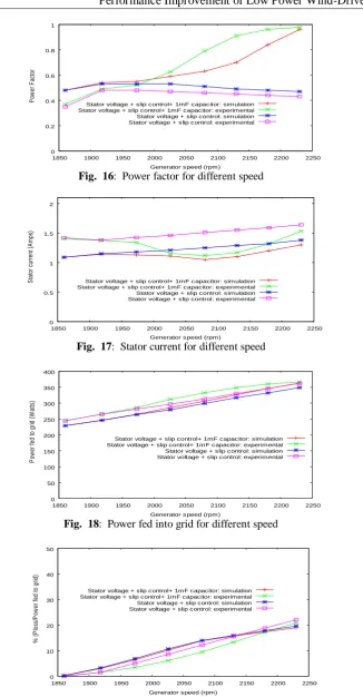
Fig. 16: Power factor for different speed
0 0.5 1 1.5 2
1850 1900 1950 2000 2050 2100 2150 2200 2250
S
ta
to
r
cu
rr
en
t (
A
m
ps
)
Generator speed (rpm) Stator voltage + slip control+ 1mF capacitor: simulation Stator voltage + slip control+ 1mF capacitor: experimental Stator voltage + slip control: simulation Stator voltage + slip control: experimental
Fig. 17: Stator current for different speed
0 50 100 150 200 250 300 350 400
1850 1900 1950 2000 2050 2100 2150 2200 2250
P
ow
er
fe
d
to
g
rid
(
W
at
ts
)
Generator speed (rpm)
Stator voltage + slip control+ 1mF capacitor: simulation Stator voltage + slip control+ 1mF capacitor: experimental Stator voltage + slip control: simulation Stator voltage + slip control: experimental
Fig. 18: Power fed into grid for different speed
0 10 20 30 40 50
1850 1900 1950 2000 2050 2100 2150 2200 2250
%
(
P
lo
ss
/P
ow
er
fe
d
to
g
rid
)
Generator speed (rpm) Stator voltage + slip control+ 1mF capacitor: simulation Stator voltage + slip control+ 1mF capacitor: experimental Stator voltage + slip control: simulation Stator voltage + slip control: experimental
Fig. 19: Percentage of power loss in the external resistor with respect to power fed to grid for different speed
VII. CONCLUSION
power factor have been improved in comparison to a conventional slip power control scheme. Moreover, there is a significant reduction in the line current and increase in the active power supplied to the grid. The reactive power (inductive) demand has also reduced, as the power factor improves throughout the range of operation and which does not vary appreciably with the wind speed. Using the simulation model, an optimum value of capacitance has been found to compensate the reactive power throughout the range of control. This scheme is useful for wind energy conversion system (WECS) where wind speed varies over wide range.
VIII. APPENDIX
WOUND ROTOR INDUCTION MACHINE DATA: 1kW, three phase, 60Hz, 400V, 2.8A, 1690rpm, star connected: Stator resistance, R1 = 6.28 Ω, Stator reactance, X1 = 15.9Ω, ecnatsiser rotoR, R2 = 1.5 Ω, Rotor
reactance, X2 = 3.6 Ω, and Mutual reactance, Xm = 118.01Ω
REFERENCES
[1] S. Engelhardt, I. Erlich, C. Feltes, J. Kretschmann, and F. Shewarega, “Reactive power capability of wind turbines based on doubly fed induction generators,” IEEE Trans. on Energy conversion, Vol. 26, No. 1,pp. 364-372,May 2011.
[2] E. A. DeMeo, “20% electricity from wind power: An overview,” IEEE Power Energy Soc. General
Meeting-Convers. Del. Electr. Energy 21st Century, Pittsburgh, USA, pp. 1-3, 20-24 July, 2008.
[3] V. Subbiah, and K. Geetha, “Certain investigations on a grid connected induction generator with voltage control,” IEEE International Conference on Power Electronics, Drives and Energy Systems, New Delhi, India, pp. 439–444, 8-11 Jan., 1996.
[4] B. Singh, “Induction generators – a prospective,” Electric Machines and Power Systems, Taylor & Francis, Vol. 23, pp. 163-177, 1993.
[5] W. E. Leithead and B. Connor, “Control of a variable speed wind turbine with induction generator,” Control‟94,21-24 March 1994, pp. 1215-17
[6] El-Sharkwai and S.S. Venkata, “An daptive power factor controller for three-phase induction generators”, IEEE on PAS, vol.104. No. 7, July 1985.
[7] S. S. Murthy and C.C. Jha, “Analysis of grid-connected induction generators driven by hydro/wind turbines under realistic system constraints”, IEEE Transaction on Energy Conversion, March 1990, pp.1-7
[8] S. S. Babu, G. J. Mariappan, and S. Palanichamy, “A novel grid interface for wind-driven grid-connected induction generators,” IEEE/IAS International Conference on Industrial Automation and
Control, Hyderabad, India, pp. 373–376, 5-7 Jan., 1995.
[9] A. F. Almarshoud, M. A. Abdel-halim, and A. I. Alolah, “Performance of grid-connected induction generator under naturally commutated ac voltage controller,” Electric Power Components and
Systems, Taylor & Francis, Vol. 32, pp. 691-700, 2004.
[10] L. Holdsworth, X.G. Wu, J. B. Ekanayake, and N. Jenkins, “Comparision of fixed speed and doubly-fed induction wind turbines during power system disturbances,” IEE Proc. Generation Trans. Distrib., Vol. 150, no. 3, pp. 343-352, May 2003.
[11] D. Ramirez, S. Martinez, C. A. Platero, F. Blazquez, and R. M. De Castro, “Low-voltage ride-throughcapability for wind generators based on dynamic voltage restorers,” IEEE Trans. on Energy
conversion, Vol.26, No. 1,pp 195-203,May 2011.
[12] F. Bu, W. Huang, Y. Hu, and K. Shi, “An excitation-capacitor-optimized dual stator-winding induction generator with the static excitation controller for wind power application,” IEEE Trans. on Energy
conversion, Vol. 26, No. 1,pp. 122-131,May 2011.
[13] M. S. Jamil Asghar and H. Ashfaq, “Speed control of wound rotor induction motors by ac regulator based optimum voltage control,” International Conference on Power Electronics and Drive Systems
(PEDS), Singapore, pp. 1037-1040, 2003.