Energy Consumption through Cluster Head Selection in
Wireless Sensor Networks
1
Upendar Gandham,
2E Jagadeeswararao,
3G Stalin Babu
1Software Engineer in Value Labs, Hyderabad, Telangana, India 2Dept. of CSE, CMR College of Engineering & Technology, Hyderabad, India 3Dept. of CSE, Aditya Institute of Technology and Management, Tekkali, AP, IndiaAbstract
Wireless Sensor Networks (WSNs) are being utilized widely to
monitor and observation in a few fields like military territory, agricultural fields, forests, atomic reactors and so on. A Wireless
Sensor Network for the most part comprises of an expansive number of small and minimal effort sensor nodes powered by small non-rechargeable batteries and furnished with different detecting
gadgets. It is normal that it will be all of a sudden dynamic to
assemble the required information for infrequently when something
is recognized, and after that residual to a great extent latent for drawn out stretches of time. In this way, efficient power saving
plans and relating algorithms must be produced and planned keeping in mind the end goal to give sensible energy utilization
and to enhance the network lifetime for WSNs. The cluster-based
method is one of the great ways to deal with diminish energy
utilization in wireless sensor networks. The lifetime of wireless
sensor networks is stretched out by utilizing the uniform cluster
area and adjusting the network stacking among the clusters. In this exploration work, different energy efficient plans apply in WSNs have been considered. The clustering based approach has been
contemplated and an adjusted convention has been executed which
depends on determination likelihood. The sensor just transmits when the limit level is accomplished for this choice potential. It
chooses a node as a cluster head if its lingering energy is more than framework normal energy and have less energy utilization rate in
the past round. The objectives of this plan are, increment security time of the network, and limit loss of detected information.
Keywords
Wireless Sensor Networks, Energy Efficiency, Network Lifetime, Stability.
I. Introduction
The use of Wireless Sensor Networks (WSNs) in different fields, for example, mechanical control, strategic military applications, natural and security observing, is generally recognized [1-2]. In wireless sensor networks, sensor nodes are frequently powered by non-rechargeable batteries. When a battery gets depleted, at
that point the battery life expectancy is completely conveyed to
a stop and should be supplanted. Notwithstanding a few research endeavors, energy utilization has remained a key test amid the plan of battery powered WSNs [3]. Energy gathering is a procedure that as of late discovered its way into the networking circles. It was exclusively presented for wireless sensor networks. It gives
an extra wellspring of energy that can be gathered from conditions
that incorporate sun based and wind energy. As per [4-5], the
method has the ability to immensely broaden the traverse of life
of wireless sensor networks. It drags out life expectancy as well as empowers sensor nodes run consistently. In WSNs, directing is frequently used to draw out the life expectancy of a network, since wireless sensor nodes are power-compelled gadgets. There
is plenty of research done in the course of recent decades in the
region of directing convention for WSNs and this is because
of its present day huge and applications to the field of sensor networks [6]. Given the constraints of assets accessible to a sensor network, it isn’t promising to have every node convey information to the base station. Network adaptability has been accomplished
by method for making clusters which are made out of gathered
sensor nodes. The cluster head (CH) is utilized to indicate the pioneer of each cluster. The advantages of clustering incorporate course limitation, lessening in overhead collecting to topology support, diminishment of rate of energy admission, decreased volume of parcels to be handed-off [7-8]. This work significantly broadens the customary directing convention known as “Low-energy versatile clustering chain of importance” (“LEACH”) to “Energy Neutral LEACH”. Energy nonpartisan “Filter” endeavors to limit the exchange scope of cluster heads (CHs) by presenting a Gateway Node (GN) to each cluster. The “EN-LEACH” does
acquire the advantages of “Drain” as well as keeps all sensors in
an energy impartial state and by so doing, the measure of energy
taken by every one of the sensors is not as much as the measure of
energy reaped at a specific time [9]. General network throughput in energy gathering is enhanced in wireless sensor networks. II. Related work
Numerous researchers have been done on clustering sensor nodes
which offer novel techniques for clustering. The fundamental
distinction between these strategies is the way to choose cluster
heads. The first and most famous clustering conventions proposed for WSN is the LEACH [Heinzelman,2000].LEACH frames clusters by utilizing an appropriated algorithm, where nodes settle on self-sufficient choices with no unified control. The activity of LEACH is separated into rounds and each round comprises of setup stage and the unfaltering state stage. In the setup stage, the clusters are sorted out and cluster heads are chosen. Every sensor node produces an irregular number in the vicinity of 0 and 1. On the off chance that this number is smallr than the edge esteem T(n), the sensor node chooses itself as a CH. Condition (1) characterizes the T(n) where P is the asked for proportion of the cluster heads in the WSNs and r is the check of current round. The G is the arrangement of sensor nodes that were not chosen as a cluster head in last 1/p rounds.
The HEED [Younis, 2004] is not quite the same as LEACH in the way in which CHs are chosen. It proposes an iterative and dispersed clustering. A hopeful cluster head pronounces its status just the nodes that are in its radio range. Both choosing CHs and
joining clusters are performed in view of the half and half blend
of two parameters. The essential parameter relies upon the node’s leftover energy and chooses competitor cluster heads. The elective
parameter is the intra-cluster correspondence cost and decides the
last cluster heads. This cost are identified with the cluster attributes, for example, its size and power levels of information transmission. This algorithm utilizes a probabilistic model
This algorithm like LEACH is separated into rounds that amid
the start-up stage every node produces an arbitrary number in
the vicinity of 0 and 1 and has a limit esteem. On the off chance that the irregular number is smallr than the edge esteem, the node distinguishes itself as cluster head. At the end of the day, the limit esteem head decision technique utilizing fluffy rationale to conquer the imperfections of LEACH. In this strategy, every node knows about its area facilitates. Cluster heads are chosen by the construct station, situated in light of the possibility of every node in each round. For every node, a shot esteem is figured utilizing fluffy derivation framework with input parameters: remaining energy, focus and centrality by the base station. Base station chooses the node with the most elevated possibility as CH and communicate the whole network. The created overhead of sending and accepting data is much in network and there is just a single chose CH for each round, while more CHs are required for adjusting energy utilization.
The LEACH-FL [Ran, 2010] convention is the same as Gupta convention for enhancing LEACH convention. The base station chooses nodes with higher possibility as cluster heads. This technique utilizes three descriptors: node leftover energy, node degree and separation from base station to compute the shot esteem. In the event that the possibility is smallr than the predefined limit, at that point that node turns into a cluster head.
The FLCFP algorithm [Mhemed, 2011] presents a strategy for shaping clusters. This algorithm works much like LEACH and they vary in how the clusters are framed. In FLCFP non cluster head nodes compute an incentive with fluffy rationale for each CHs. Three descriptors for this technique are: energy level of the cluster head, remove from the base station and the separation between the cluster heads. A node joins the cluster head which is the most astounding worth got.
The LEACH-ERE algorithm [Lee, 2012] utilizes two descriptors: leftover energy and expected lingering energy (ERE) of the sensor nodes for ascertaining the shot an incentive with fluffy rationale. The greater shot implies that the node has more opportunity to be a CH. Keeping in mind the end goal to assess the ERE, the normal energy utilization (EEC) is required. ERE in each round is distinction between node remaining energy and node EEC. In this algorithm, the quantity of clusters is settled and decided toward the beginning of networking [10].
III. Problem Definition
Clustering is efficient scheme for data aggregation in the wireless sensor network. In which each sensor node sends data to the aggregator node means Cluster Head (CH) and then cluster head
perform aggregation process on the received data and then send
it to the Base Station (BS). Performing aggregation function over cluster-head still causes significant energy wastage. In case
of homogeneous sensor network cluster-head will soon die out and again re-clustering has to be done which again cause energy
consumption. In this paper we would like to propose an algorithm that performs data aggregation process within a cluster. In this propose algorithm we will focus on avoiding reclustering, reduce the overhead of clustering process, reduce the load over cluster head, and reduce the energy consumption within cluster in
large-scale and dense sensor networks with the help of cluster head
selection and cluster formation. To achieve these objectives we would like to present an algorithm in whichCHs are selected from same cluster in each round and data are sent to CH in multi-hop manner to prolong the lifetime of network.
IV. Proposed Methodologies
A. Key Management
Key agreement in wireless sensor networks is nontrivial. To achieve security in wireless sensor networks, it is important to be able to perform various cryptographic operations, including encryption, authentication, and so on. Keys for these cryptographic operations
must be set up by communicating nodes before they can exchange
information securely. Key management schemes are mechanisms
used to establish and distribute various kinds of cryptographic keys
in the network, such as individual keys, pair wise keys, and group keys. Key management is an essential cryptographic primitive upon which other security primitives are built. Most security requirements, such as privacy, authenticity, and integrity, can be addressed by building on a solid key management framework. In fact, a secure key management scheme is the prerequisite for the security of these networks, and thus essential to achieve secure infrastructure in Sensor Networks. The challenge of designing key
management protocols for sensor networks lies in establishing a secure communication infrastructure; some cryptographic
information (e.g., a key) is normally preloaded in sensor nodes before deployment, and allows sensor nodes to perform secure communications with each other using algorithms.
Most schemes do not assume prior knowledge of the network
deployment topology and allow nodes to be added to the network
after deployment. The schemes must have low computational and low storage requirements. There are four types of key management schemes: trusted server, self-enforcing, key predistribution and public key cryptography. When designing a key management scheme for WSNs, designers should take the following five major resource constraints of sensor nodes into consideration: (1) limited energy, (2) limited memory, (3) Limited computing power, (4) limited communication bandwidth, (5) limited communication range. The key management includes key generation, key distribution, and key storage. The enhanced key management in this
version can perfectly eliminate the impacts of node compromise attacks on links between non-compromised nodes which most
existing key management schemes have faced. In this paper we
surveyed various key establishment and distribution schemes and
compared scheme-I and scheme-II with scheme-III.
B. Scheme-I
The establishment of keys consists of four phases including initialization, pair wise key establishment, cluster key establishment and key renewing.
1. Initialization
Before deployment the node receives a master key K,a Node identifier ID and a random vector a
2. Pair Wise Key Establishment
The node sends broadcasting and receives broadcasting from its neighbors. The pair wise keys are established by combining the master key with its neighbor vectors.
Cluster key Establishment: Each node establishes the cluster key by combining the master key and cluster head‟s identifier. Renewing of keys: The keys are renewed to ensure the network security including the pair wise key and cluster key. The nodes
in the network delete all the keys except the cluster keys and
generate a new random number.
to the uncaptured node in unicast mode. If any cluster head is captured, the members would delete all the information related to it and join into another cluster through its neighbors.
Advantage:
Communication overhead is low. •
Increased Resilience. •
(as a compromised node does not reveal Information about other
nodes that are not directly communicating with the captured
node.)
Disadvantage:
Memory overhead s high [a distinct pair Wise key for every •
other node in the Network]
Not scalable for large networks. [Each node has a pool] •
C. Scheme-II
The establishment of keys consists of four phases which includes key pre-distribution phase, a shared key discovery phase, a path key establishment phase and key ring reduction phase.
1. Key Pre-distribution Phase
P keys of the key pool are selected randomly from the key space. The key ring of each node, a random subset of m keys from the key pool is stored on the memory of each node before deployment.
2. Shared –Key Discovery Phase
After the nodes are deployed,a shared key discovery phase is performed, where two neighbor nodes find out their common key in their key rings and use it as a shared key. Each node broadcast
key identities in its key to discover a common key with neighbor
nodes.
3. Path Key Establishment Phase
After a shared key discovery phase, if two nodes do not have a common key, then a path key establishment phase is performed between the two nodes [9].
4. Key Ring Reduction Phase
The keys in a key ring are used to establish pair wise key with neighbors. The attacker can easily extract the keys of a key ring in a captured node. To improve the security ,after key setup, each node erases m-m’ keys selected .Therefore the total number of keys in the key ring comes to m’.
Advantage:
No of key used is low so memory overhead is low. •
Scalable. [Each node has a set of keys a common pool] •
Disadvantage:
As pre distribution has three phases for distribution hence •
communication overhead is high.
D. Scheme-III (Proposed method)
The network has entities like sensor nodes, base station, cluster head which are deployed in the field, the establishment of key
consists of
1. Initialization
Each node receives a master key “K”, a node identifier ID, cluster key Kc which is formed by combining the master key and ID of the node. The cluster key Kc is generated by the cluster head and
shared by the nodes in that particular cluster, the nodes from that cluster use the key to decrypt the data. Nodes will only use this key when they are serving as a cluster leader. Each node has a key Ks which is generated by the base station and pre deployed
to all sensor nodes. The network key Kn is generated by the base
station, pre-deployed in each cluster node, and shared by the entire sensor network.
2. Cluster Key
Clustering algorithm clusters the nodes and a node will act as a cluster head. If the cluster head is captured by the attacker the
cluster head will automatically disconnect with their nodes and
if a node is captured it will disconnect with the neighbor. By this node capture attack is reduced. If the same node is acting as a cluster head it has a risk of resource constraints. So we modify the discovery process.
3. Authentication
For the communication between the nodes the nodes will
authenticate the neighbor by the nonce which is generated by
the base station.
4. Path declaration
After the path is declared, using the session key (Ks) the message
is encrypted and send. After the transmission is over the session key is erased in order to reduce the node capture attack.
In our proposed scheme a session key is generated and using •
the key the message is encrypted and sends. Using the routing
protocol the path is declared and all the nodes in the path involved in communication are kept active whereas all the
other nodes are kept sleeping in order to lessen the Energy consumption.
Sensor nodes within a cell periodically negotiate among
•
each other to elect the coordinator in every round. For each round, only one node stays active to be a coordinator, while the others fall into sleeping mode. Doing this significantly
reduces the energy consumption because nodes in the idle state spend much more energy as compared with the sleeping
state. Analysis in [31] has shown that energy consumption ratio for Sleep: idle: receive: transmitis 0.13:0.83:1:1.4. It
also reduces the network congestion because the number of
nodes participating in transmission/reception is decreased. On the other hand, frequent change of coordinator role helps the particular nodes not running out of its energy quickly. Therefore, it can prolong nodes as well as the network lifetime. In order to control nodes in different states and transition, we employ Geographical Adaptive Fidelity. It also
reduces the network congestion because the number of nodes
participating in transmission/reception is decreased.
Advantage:
Communication overhead low •
Storage overhead low
•
Resilience low •
Disadvantage:
Fig. 1: Single Key in Node
The energy consumption in this method for cluster head CH4 can be calculated as
Econsume = (ER×Data Packet×number of member nodes)+ET = (ER× Data Packet × number of member nodes)+ (ET× Data Packet × number of member nodes)/2 Table 1: Power Consumed in µJ /mS
Message
Size (KB) Power consumed (µJ /mS)N=25 N=1 N=35 N=1 N=40 N=1 10 16.5 0.66 19.8 0.57 26.4 0.66 20 32.0 1.28 39.6 1.13 62.8 1.57 30 61.5 2.46 59.4 1.69 79.2 1.98 40 66.0 2.64 79.2 2.26 95.6 2.39 50 82.5 3.30 99.0 2.82 133 3.30 From this the energy consumption in receiving and transmitting data increases as the number of node increases in the cluster. Hence it is defined that clustering algorithm should cluster the “N” no of nodes. If N>T limit then new Ch is assigned and send “Hello Message” and cluster the nodes.
N not greater than T limit
&
N<= T limit.
By this method energy consumed by the node relates to the life of the network. In our work the message is transmitted in one
way order and hence energy consumed will be low which in turn
increase the battery life. The energy consumed in each node will be updated in the NAT table by the base station which in turn
select the node which has high energy and assigns a weight and
elect those nodes as CH after “T” time interval.
E. MULTIPATH Broadcast Routing Protocol
There are three types of routing protocols: Proactive Protocols, Reactive Protocols and Hybrid Protocols. Proactive protocols
are table-driven that constantly update lists of destinations and
routes. Reactive protocols respond on demand. Hybrid protocols combine the features of reactive and proactive protocols. The main goal of routing protocols is to minimize delay, maximize network throughput, maximize network lifetime and maximize energy efficiency. In this paper we propose a new protocol which is Reactive protocol, respond on demand. All the existing protocols take the minimum energy path. Whereas the multi-path
routing schemes distribute traffic among multiple paths instead of routing all the traffic along a single path. In multi-path routing it is
necessary to know number of paths that are needed and choosing
the appropriate paths in the total number of available paths [4]. Clearly, the number and the quality of the paths selected dictate the performance of a multipath routing scheme. The proposed
work is intended to provide a reliable transmission of data for data synchronization at the destination on environment with low
energy consumption. This is done by efficiently utilizing the
energy availability and the received signal strength of the nodes to
identify multiple routes to the destination. The proposed protocol spreads the traffic over the nodes lying on different possible paths between the source and the destination. The rationale behind traffic
spreading is by considering the energy so that the overall lifetime
of the network will be increased. The sequence number is assigned to each packet of data for data synchronization at the destination. The objective is to assign more loads to underutilized paths and less
load to over-committed paths so that uniform resource utilization
of all available paths can be ensured. This protocol is intended
to provide a reliable transmission environment with low energy
consumption, by efficiently utilizing the energy availability and
the received signal strength of the nodes to identify multiple
routes to the destination. Simulation results show that the energy efficient adaptive multipath routing scheme achieves much higher performance than the classical routing protocols, even in the
presence of high node density and overcomes simultaneous packet
forwarding. In the proposed routing protocol the traffic is spread
over the nodes lying on different possible paths between the source
and the sink, in proportion to their residual energy and received signal strength. The rationale behind traffic spreading is that for a given total energy consumption in the network, at each moment, every node should have spent the same amount of energy. The
objective is to assign more loads to under-utilized paths and less load to over-committed paths so that uniform resource utilization
of all available paths can be ensured. Multipath Broadcasting is cost effective for heavy load scenario, while a single path
routing scheme with a lower complexity may otherwise be more
desirable.
Consider two clusters with 20 nodes. In cluster 1, the source node A wants to send data to the destination node B in cluster 2.Source node A send the data to the cluster Head in cluster1.The CH1 forwards the data to the base station. The base station find the destination node B location using the NAS structure and send the data to the destination cluster. The cluster Head 2 receives the data and floods the data to all the nodes in the cluster. A multipath is
formed and the data is divided and assigned a sequence number
The destination node receives the data from all path and arrange
the data according to the sequence number and decrypt the data
and get the correct message. The difference between the time
after construction of packets before sends and time after reception
of all packets is called latency. The ratio of total no of packets
transmitted to the total latency for those packets transmitted under
current cluster head is called throughput.
Latency = Time after construction of packets - Time after reception
of packets
Throughput = Total no of packets transmitted Total latency
tabulated for varying message size. The proposed scheme-III consumes less energy for encryption. Total Energy consumed is
also calculated with the energy spent for receive and transmit
of message.
1. Cluster Head Selection
The design of LEACH is better suited to WSNs that run on battery power. The scheme used for cluster heads selection in a way turns
the nodes into cluster heads thereby bringing about an even energy
intake among nodes. Nodes with high energy collection rate are expected to have higher likelihood to be selected as cluster heads. It is also expected that no time limit is placed on a node to become the cluster head. In “Energy Harvesting Wireless Sensor Networks (EHWSNs)”, energy is unlimited and the energy harvesting rates tend to vary between nodes. The energy collected by any sensor node cannot withstand the heavy energy intake of a CH in practice. According to [9-10], one option to salvaging this situation is the
application of a cluster head rotation scheme as is applied to the
conventional clustering algorithms.
(a). Cluster Formation
On the initial deployment, the Base Station (BS) delivers a layer-one signal using minimal energy level. Nodes listening on this broadcast message reset their layer to 1. Subsequently, the base
station upturns its energy power to achieve the next layer in order
to deliver a layer-two signal. In this case, all nodes listening on the
new broadcast message but were unable to set the previous layer
are able to set their layer to 2. This process proceeds accordingly pending when the BS delivers matching messages to all layers respectively. After dividing the network into layers and picking the CH, individual nodes can choose any cluster of interest and relay such interest to the CH. It then becomes a member of cluster. In choosing the cluster, nodes have to pay attention to proximity with the CH. In order to avoid collision individual nodes have to relay the information to the CH via “Carrier Sense Multiple Access (CSMA) MAC” protocol. Each CH obtains all the communications from the sensor nodes that wish to be contained in the cluster, and given their volume, generates a “time division multiple access (TDMA)” schedule of equivalent size. This takes place after several time intervals. The subsequent step is to relay to each
one of its cluster node when it will again deliver information
according to the TDMA schedule which is disseminated across to the nodes in the cluster.
Table 1: Algorithm for setup phase
for each (node j) 1.
j selects random number y between 0 and 1. 2.
If
3. (y < T (j)) j becomes CH. 4.
j broadcasts an advertising message for its CH status
5. then.
CH waits for join-request 6.
Else 7.
j becomes a NCH node then. 8.
NCH chooses the CH, this selection is based on RSS of 9.
Advertise.
NCH send join request to CH and become a member of its 10.
Cluster. End 11. if.
for each (CH) 12.
CH creates TDMA schedule for NCH. 13.
Each NCH communicates to the CH in its time slot. 14.
End for 15.
End for 16.
(b). Gateway Selection
Controlling the rate of data delivery is an attempt to keep the
volume of transmissions at a minimum thereby saving more
energy. The distance of each cluster may be quite long in which some CHs dies while trying to exchange messages directly with the BS. In order to resolve this situation, individual CH utilizes several transitional nodes along the path towards the BS to relay CH data. The role of BS is to identify all GNs in each cluster. The
id and the corresponding locations of gateway nodes together with
the chosen CH are transmitted by the BS. There are predefined total number of nodes which are allocated to be GNs and CH. Given that the id and the locations of gateway nodes are transmitted, individual CH have to select the nearest as the middle node and notifies it. The gateway nodes play the role of linking the CH to the BS. They also control delivery of packets received from the CH to the BS. This means that the CH can conserve energy during the course of data delivery.
(c). Steady State Phase
Immediately following the formation of CHs, GNs cluster, and TDMA-based schedules, delivery of data commences. The cluster
head that are not nodes obtains the sensor data and delivers same
the cluster head within their apportioned time slices. The radio
within the cluster head node has to be on in order to receive the data
from the nodes that are in the cluster.The amount of information transmitted by a sensor determines its energy intake. It is therefore
worthy of mentioning that in order to energy neutral operation must
be taking into consideration in the design of routing protocols. In our proposed protocol, two kinds of message exchanges occur in the cluster maintenance segment. They are namely: “intra-cluster” communication and “inter-cluster” communication.
(d). Intra-Cluster Communication
For each cluster, the data generated by sensor node is delivered to the CH. These packets of data are sent to the neighboring node having the shortest distance from CH. The following node relays towards the CH in a similar way. Intra-cluster communication is performed by means of “TDMA” technique. In this time interval, CH allocates time slices to the node in the cluster. Algorithm listing 2 presents the Intra-cluster communication execution process. Table 2: Algorithm for Intra-cluster communication
for each (Cluster) 1.
for each Non-Cluster head Si and Sj 2.
for each Cluster Head (CH) 3.
4. Si wishes to send its sensed data to CH 4.
5. S
6. i transmits data to CH
Else 7.
S
8. i transmits data to Sj (Sj is a Relay node)
S
9. j transmits data to CH
End if 10.
End for 11.
End for 12.
End for. 13.
In the intra-cluster algorithm above; represent the
distance between sensor node Si and cluster head is
the distance between sensor node Si and its neighbor Sj.
(e). Inter-Cluster Communication
using the single hub with CH class of sensors. The CHs then
assembles the information obtained from cluster members for
onward direct delivery to the BS. But during the inter-cluster communication in EN-LEACH (see Fig. 6), individual CH gets packets of data from with its cluster members. The acceptance of
all data is followed is followed by the aggregation of the data by
individual CH. This results in a single composite message. The
aggregated message is then delivered to its gateway node and yet
again the data is delivered to the BS through the multi-hub path the gateways are utilized in this process. That is, cluster Heads-Gateway nodes-cluster heads…repeatedly until it reaches the BS. During this process, the other nodes are kept asleep to save energy (see algorithm listing 3).
Table 3: Algorithm for Inter-cluster Communication
for each (Layer i) 1.
for each Cluster Head (CH
2. i)
for each Gateway node (GN
3. i)
CH received data from Non-cluster head 4.
CH aggregate the received data 5.
6. CH
7. i transmits aggregated data to GNi then
GN
8. i transmits aggregated data to BS
Else 9.
CH broadcast data to the next Layer CH 10.
End if 11.
End for 12.
End for 13.
Fig. 2: Clustering Model of Proposed Routing (EN-LEACH) Protocol
V. Evaluation Metrics
A. Secure Connectivity
We measured the secure connectivity rate of the network size of
50 nodes without path key establishment phase and present the results in fig. 2. As seen from fig. 2, in scheme-III has a single key
in the network each node can communicate with any node that falls into its communication range making the secure connectivity rate
100% In the pair wise key establishment scheme the connectivity is also 100% since each node carries (N1) keys for every other node in the network. In random key redistribution scheme each node connects to other nodes with the probability of P. Simulation
results also show that the secure connectivity rate of the network
is 70% which is determined by the value of P
Fig. 3: Secure Connectivity
B. Communication Overhead
Figure: 3 illustrates the communication overhead of each key management scheme. In scheme III there is no communication
overhead because we assign a single key to all nodes in the
network before network deployment. In scheme I &II have more communication overhead than Scheme-III. As in pair wise key
establishment scheme each node has single key while in the random key predistribution schemes each node has number of keys
equal to the ring size of the node. For example in the case of 50 nodes in basic random key distribution, scheme-II communication overhead due to key establishment is 1800 bytes whereas in pair wise key establishment scheme-I this overhead is equal to only 270 bytes.
Fig. 4: Communication Overhead in Bytes
C. Memory Overhead
Figure: represents the memory overhead of each key management scheme for different network sizes. The result shows that scheme-III uses only 8 bytes of memory which it is the size of two key. In pair wise key establishment scheme, since eachsensor node is loaded with a distinct key for every other node in the network, this scheme’s memory overhead (N-1) X4 bytes per node is bytes. For example, a sensor node in a WSN consisting of 40-node incurs 36-byte memory overhead. In our simulation, scheme-I &II employ more than 4 keys per sensor
Table 2: Evaluation Metrics (Scheme-I,II,III)
s-1 s-2 s-3
Scalability Large Large Large
Secure
connectivity 80% 70% 100%
Memory overhead
(N-1)keys are used in a node (storage high)
>3 keys randomly selected (com high)
Only 3 keys are used in a node Communication
overhead >7 messages, Low > 7 messages, high 7 messages, Low
Resilience High Low Low
Energy
D. Resilience Against Node Capture
Fig. 4 present the resiliency against node capture. Resilience is
measured in terms of the number of secret keys a compromised
node reveals. If a sensor node‟s secret keys are revealed we assume that sensor node is also captured. From Chart- 4, we can see that pair wise establishment scheme is the most efficient and resistant. (Scheme–I )while in scheme-III the key it is enough to capture one node to gain control to the entire network. The simulation results also show that scheme-I & II has better resilience compared to scheme-III
Fig. 5: Resiliency Against Node Capture
VI. Performance Analysis
In an attempt to thoroughly investigate and profile the energy consumption in a WSN, we performed a wide set of simulation scenarios. Every node in a WSN consumes energy mainly for transmission and reception purposes. It transmits routing and
data messages and thus the energy consumption depends on the
node location and the data messages it generates or forwards. To quantify these dependencies, we have run a scenario set with no malicious nodes in the network,100 nodes are placed in a 10x10 grid. Ten nodes transmit data to the base station. The simulated application issues one packet of 10K bytes every two seconds while the Beacon interval is 0,5 seconds . We have measured the energy consumption of nodes A, B, E, F,G. Based on the obtained results, we have calculated the energy consumption for the case
where both data and routing messages circulate in the network and the energy consumption when only routing messages are
exchanged.
In this analysis, we consider two parameters that decide the outcome of our model. They are:
Throughput 1.
Latency. 2.
The difference between the time after construction of packets
before sends and time after reception of all packets is called
latency. The ratio of total no of packets transmitted to the total
latency for those packets transmitted under current cluster head
is called throughput.
Latency = Time after construction of packets - Time after reception
of packets
Throughput = Total no of packets transmitted Total latency
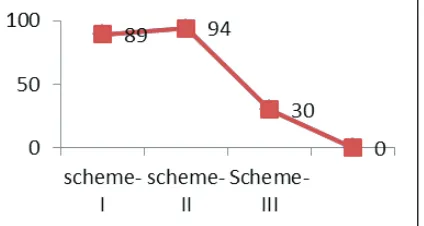
Packets transmitted (session 1) = 100000 Latency = 3000ms
Packets transmitted (session 1) = 109583 Latency = 4000ms
Throughput = 100000+109583 3000+4000
=29.940%
Thus our proposed model raises the throughput up to 30%.
Fig. 6: Node Registration with Cluster Head
The Encryption algorithm used for encryption is DES (Data Encryption Standard).The energy consumed for encryption is tabulated for varying message size. The proposed scheme-III consumes less energy for encryption. Total Energy consumed
is also calculated with the energy spent for receive and transmit
of message.
Fig. 7: Energy Consumed for Encryption for three Schemes The Decryption algorithm used for Decryption is DES (Data Encryption Standard).The energy consumed for Decryption is tabulated for varying message size. The proposed scheme-III consumes less energy for Decryption. Total Energy consumed
is also calculated with the energy spent for receive and transmit of message
Fig. 9: Total Energy Consumed for Three Schemes
VII. Conclusion and Future Work
In this paper the three schemes were compared and their efficiency through various metrics were tabulated in table .This paper
investigates and evaluates the most important key management
schemes in wireless sensor networks. Namely, scheme-III, Scheme-I, scheme-II are explained and evaluated against metrics and attacks using JAVA simulator. Our future research directions
involve comparing more key management schemes using different
metrics and larger network sizes.
References
[1] A Krishnakumar, V. Anuratha,“An energy-efficient cluster head selection of LEACH protocol for wireless sensor networks”, 2017.
[2] AbdElwahabFawzy, AsmaaAmer, Mona Shokair, WaleedSaad,“Proposed intermittent Cluster Head selection scheme for efficient energy consumption in WSNs", 2017. [3] MadhuPatil, Chirag Sharma,“Energy efficient cluster head
selection to enhance network connectivity for wireless sensor
network”, 2017.
[4] Maryam Kalantari; Gholamhossein Ekbatanifard,“An energy
aware dynamic cluster head selection mechanism for wireless
sensor networks”, 2017.
[5] I.F. Akyildiz, W.Su,Y.Sankarasubramaniam, E.Cayirci, “Wireless Sensor Network: A Survey,” Computer Networks, 2000.
[6] SongtaoGuo, Cong Wang, Yuanyuan Yang,“Joint Mobile Data Gathering and Energy Provisioning in Wireless Rechargeable Sensor Networks,” Mobile Computing, IEEE Transactions on, Vol. 13, 2014.
[7] Jamal N. Al-karaki, Ahmed E. Kamal,“Routing techniques in wireless sensor networks: A survey”, IEEE Wireless Communications, December 2004.
[8] Y. Geng, C. Hong-bing, H. Su-jun,“NHRPA: A novel
hierarchical routing protocol algorithm for wireless
sensor networks,” China Universities of Posts and Telecommunications, September 2008.
[9] Meenakshi Diwakar, Sushil Kumar,“An Energy Efficient Level Based Clustering Routing Protocol for Wireless Sensor Networks”, School of Computer and System Sciences Jawaharlal Nehru University, India, April 2012.