Performance Analysis of Channel Equalizers in
Optical Communication for Next Generation
Systems
Dr.R.Deepa
Professor, Nehru Institute of Engineering and Technology, Coimbatore
S.M.Deepa
Asst. Professor, Department of EEE, Nehru Institute of Engineering and Technology,
Coimbatore
B.Nandhini
Asst. Professor, Department of EEE, Nehru Institute of Engineering and Technology,
Coimbatore
Abstract: Nonlinear impairments in optical communication systems have become the major performance limiting factor of optical communication systems. The equalizer based on linear filters has limited compensation capability. Therefore, nonlinear models based equalizers are proposed for performance enhancement. Migration towards greater speed and longer links in fiber optic systems boost problems with dispersion in optical fibers. In this paper, a channel equalizer at the transmitter based on minimum standard deviation is proposed. The performance analysis of the proposed algorithm is compared with existing techniques. The results presented in this paper can be used to design equalizers for the next generation’s optical communication system.
Keywords – Optical Communication, Equalizer, Minimum Standard Deviation
I. INTRODUCTION
For gigabits and beyond gigabits transmission of data, the fiber optic communication is the ideal choice. This type of communication is used to transmit voice, video, telemetry and data over long distances and local area networks or computer networks. Fiber optics communication was first developed in 1970s which brought great breakthroughs for telecommunications industry [1]. A fiber optics communication system consists of a transmitter which is used for encoding information into optical signals for transmission and a receiver whose function is to decode messages from received signals. A fiber Optic Communication System uses light wave technology to transmit the data over a fiber by changing electronic signals into light. The light forms an electromagnetic carrier wave that is modulated to carry information. Fiber is preferred over electrical cabling when high bandwidth, long distance, or immunity to electromagnetic interferences are required. Several new classes of optical communication networks are presently emerging [2]. For example, Code Division Multiple Access networks using optical signal processing techniques have recently being introduced [3].
The capacity of the optical communication link is subject to the equipment available and its electronics, the communications channel and the type of transmission signal. There are many studies based on new modulation methods and new models for data transmission, which can handle non-linear and randomly changing optical communication channels. One such area of research to reduce complexity is channel equalizers.
form of equalization uses a linear filter that applies the inverse of the channel transfer function on the received symbols to estimate the transmitted data. Equalizers using finite impulse response (FIR) type filters have been studied in works such as [4]. Dispersion compensation techniques [5] also fall under this category. Equalizers that are specifically designed for optical communications are discussed in [6]. Since the adaptive computation of filter coefficients at gigabit per second data rates is still prohibitive, equalizers based on maximum-likelihood sequence estimation (MLSE) and maximum a posteriori (MAP) detection have been proposed to improve performance [7]. MLSE is based on the observation of a sequence of received signals and searches for the best path that maximizes the joint probability of received signals. Practical channels lead to distortions, such as Inter-Symbol Interference (ISI) and require special techniques to prevent the performance of the communication system from degrading [8]. Channel Equalization is one such extensively used technique. The aim of equalization is to ‘undo’ the effect of the channel’s non-ideal behavior. The ideal channel equalizer is one which is the exact inverse of the impulse response of the channel. Since in practice, the channel response is not known beforehand, one has to take recourse to ‘approximate’ methods of channel equalization. Most equalizers periodically update their parameters based on the channel conditions through the use of ‘training sequences’ sent by the transmitter [9], [10]. This helps in estimating the current channel conditions. The pre-distortion type adaptive channel equalization technique is based on sending the ‘training sequences’ from receiver end to transmitter end so that the process of Adaptive Equalization can be performed at the transmitter end itself by pre-distorting the data-signal before transmitting it to the receiver.
II. OPTICAL FIBER COMMUNICATION SYSTEM:
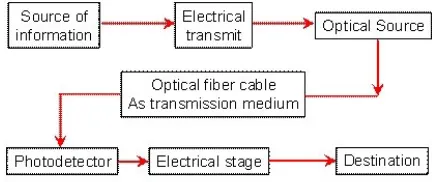
The general block diagram of optical fiber communication system is shown in Figure 1. The source provides information in the form of electrical signal to the transmitter. The electrical stage of the transmitter drives an optical source to produce modulated light wave carrier. Semiconductor LASERs or LEDs are usually used as optical source here. The information carrying light wave then passes through the transmission medium i.e. optical fiber cables. The signal reaches the receiver stage where the optical detector demodulates the optical carrier and gives an electrical output signal to the electrical stage. Finally the electrical stage gets the information back and gives it to the concerned destination.
Figure 1: Block Diagram of optical fiber communication
III. EQUALIZERS
The basic idea of a linear equalizer is simply to filter the received signal through a filter that approximates the channel inverse, i.e.
3.1 Equalization of Channel
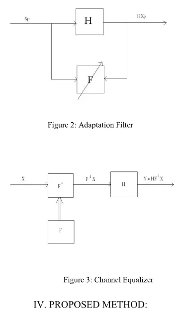
An adaptation filter that is adapted to the channel impulse response ‘H’ at the transmitter end ‘F’ is given in figure 2. ‘F’ gives an approximate estimate of channel impulse response. In Fig.2, is transmitted pilot symbols and H is channel response observed in frequency domain. F is the adaptation filter. Once f gets adapted to h, inverse filter is designed whose frequency response is . Now all the data-symbols which are transmitted from transmitter are passed through the filter and then transmitted to the receiver end through the channel. By this, the pre-distortion applied on all the symbols by the filter nullifies the distortion seen when the symbol traverse through the channel and is explained in Figure 3
Figure 2: Adaptation Filter
.
Figure 3: Channel Equalizer
IV. PROPOSED METHOD:
Minimum Standard Deviation (MSD) Algorithm is based on adaptation of the error observed. Considering the time domain channel vector H to be Gaussian and to be uncorrelated with the channel noise , the MSE (Mean Square Error) is expressed as
]
Where Ĥ is the channel estimate(with MMSE) and X H denotes the Hermitian of the matrix X. Invoking the
= 0
= 0
Considering the time domain channel vector h to be Gaussian and to be uncorrelated with the channel noise we get,
Since ;
and ,
and
In each step, the weights are adapted to a desired value for which error is minimized, in turn minimizing the standard deviation of the error. The step size decides the rate of convergence of the algorithm. It is chosen as a value between 0 and 1. For a value of nearer to 0, the algorithm will converge slowly but accurately and for the value of near to 1, the algorithm converge at a faster rate but with error. Hence is taken to be an optimum value between 0 and 1.
where, is the weight or filter coefficient of the adaptive filter in iteration, is the step size, is the error observed in iteration, x is the actual value of data. The error observed is given by
The filter adaptation is given by
And the minimum standard deviation is given by
By this process of adaptation, MSD of f is reduced and f moves towards h with every iteration. The equalization filter is designed by,
If the initialization values are close to a local minimum, the algorithm will converge towards the corresponding undesirable coefficient values. Furthermore, if the initialization values are close to a saddle point, the convergence will be slow. Additive white noise changes the locations of both the local and global minima and also makes the global minima shallower, which results in less stable global minima. The noise effect also reduces the stability of the local undesirable minima. By proper initialization of the equalizer coefficients, problems with bad convergence can be avoided.
V. SIMULATION DETAILS
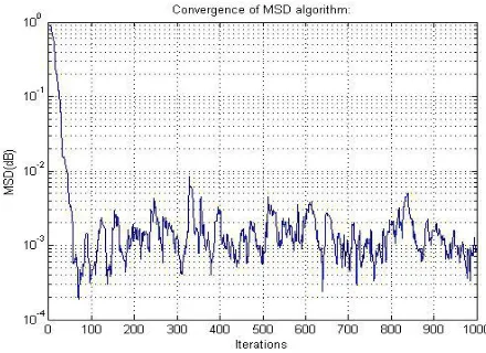
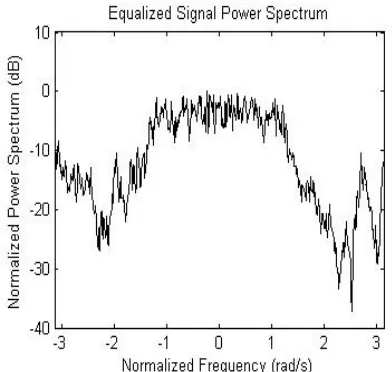
The simulation of the proposed technique is done and a graph is plotted between the number of iterations, i.e., the number of bits transmitted from the receiver to the transmitter and MSD as shown in Figure 4. It is observed that there is a steep decrease in MSD from 0-50 iterations after which an oscillatory behavior is seen. Thus, we conclude that maximum of 30-50 iterations is sufficient for the convergence of MSD algorithm in the proposed technique. The estimated channel frequency response is given in Figure 5 and the equalized power spectrum is plotted in Figure 6. The Bit Error Rate Comparison of different equalizers are plotted in Figure 7. At an error rate of 10-4, there is an improvement of 1 dB compared to Maximum Likelihood Sequence Estimation MLSE.
Figure 5: Estimated channel frequency response
Figure 6: Equalized power spectrum
Figure 7: BER comparison of different equalizers
VI. CONCLUSION
This paper presents an idea of channel equalizer at the transmitter site. The proposed algorithm uses minimum standard deviation and the weight adaptation is performed by calculating the error. Simulation results show that the proposed equalizer converges fast and achieves significant BER improvement compared with other equalizers. REFERENCES
[1] Govind P. Agrawal, Fiber-optic communications systems, 3rd ed. John Wiley & Sons Inc, 2002.
[2] X. Wang and K. Kitayama, "Analysis of beat noise in coherent and incoherent time-spreading OCDMA," IEEE/OSA Journal of Lightwave
Technology ,vol. 22, no. 10, pp. 2226-2235, 2004.
[3] T. H. Shake, "Confident performance of encoded optical CDMA", IEEE/OSA Journal of Lightwave Technology, vol. 23, pp. 1652- 1663,
[4] M. Bohn, W. Rosenkranz, F. Horst, B. Offrein, G.-L. Bona, and P. Krummrich, “Integrated optical FIR-filters for adaptive equalization of fiber channel impairments at 40 Gbit/s,” in Optical Communication Theory and Techniques , E. Forestieri, Ed. New York, NY, USA: Springer, 2005, pp. 181–188.
[5] C. Poole, J. Wiesenfeld, D. DiGiovanni, and A. M. Vengsarkar, “Optical fiber-based dispersion compensation using higher order modes
near cutoff,” J. Lightw. Technol., vol. 12, no. 10, pp. 1746–1758, Oct. 1994.
[6] T. Adalı, W. Wang, and A. Lima, “Electronic equalization in optical fiber communications,” in Proc. Int. Conf. Acoustics, Speech, and
Signal Processing (ICASSP), Hong Kong, 2003, pp. 497–500.
[7] P. J. Winzer, M. Pfennigbauer, M. M. Strasser, and W. R. Leeb, “Optimum filter bandwidths for optically preamplified NRZ receivers,” J.
Lightw. Technol., vol. 19, no. 9, pp. 1263–1273, Sep. 2001.
[8] T. L. Tung and K. Yao, “Channel estimation and optimal power allocation for a multiple-antenna OFDM system,” EURASIP J. Applied Signal
Processing, vol. 2002, pp. 330-339, Mar. 2002
[9] P.W. Wolnaisky, G.J. Foschini, G.D. Golden, and R.A. Valenzuela,“V-BLAST: an architecture for rich-scattering wireless channel,” URSI
International Symposium on Signals and Systems and Electronics, pp.295-300, 29 Sep-2 Oct 1998.
[10] S.Benedetto and E.Biglieri, “Nonlinear Equalization of Digital Satellite Channels,” IEEE Jour. On Selected Areas of Communications, vol. 1, pp.