Volume 13, Issue 10 (October 2017), PP.64 - 69
Floating Dock Island a Modern Alternative for Regulator
Cum Bridge Upstream Recreation
*Nithin Raj .M.R.
11
PG Student, Sreepathy institute of management and technology, Vavannor, Kerala technical university, Kerala, India
Corresponding Author: *Nithin Raj .M.R.
ABSTRACT:-
Tourism enhances nearly all aspects of our society. Apart from that it is important to economic changes, Human socio cultural activities and environmental development. The study was undertaken to improve the tourism possibilities of upstream portion of regulator cum bridges by applying implementable eco-friendly and low cost alternatives at the upstream portion. This paper deals with the design and construction of floating dock island at upstream to improve the tourism possibilities. The design was prepared based on Chamravattom regulator cum bridge upstream portion.Keywords:-
Regulator cum bridge, Prestressed wood lumber, Polyurethane adhesives, Stainless steel wire rope, Anchoring block, Live load, Dead loadI.
INTRODUCTION
The regulator cum bridges have numerous positive impacts including prevention of saline water intrusion, Increase in ground water table, Increase in agricultural production and improved transportation and communication facilities. Floating dock island implementation at upstream region will positively contribute the development of the region. Static floating dock islands are simple and economic gears to attract tourists which have proportional impact in the social and economic developments. Prestressed wooden lumber sections, Gallon drums, Polyurethane adhesives and steel ropes are used for the construction of a single structural unit of the floating dock island. Similar units are incorporated together to obtain the whole structure and it is anchored to the river bed using stainless steel wire ropes on stable concrete foundation. Adequate factor of safety is considered to maintain the stability of the structure and to cope up with drastic conditions. Required considerations are adopted from Indian design codes and practices.
II.
MATERIALS
AND
METHODS
The initial step of the design and construction of floating dock island is to construct the single structural dock unit.It is done using barrels, Prestressed wood lumber and stainless steel wire ropes.The lumbar and following materials are used :
4 - 2x8" pressure treated lumber. 8 feet long. 7 - 2x4" pressure treated lumber. 8 feet long. 17 - 1x6" pressure treated lumber. 8 feet long. 4 - 4x4" pressure treated posts. 8 inches long. 4 - 55gallon plastic Barrels
100ft of Wire Rope 16 - Screw in Eye Hooks 10 to 20 - L shape braces Galvanized screws and Nails Drill/Screw Driver
Hammer
Silicone Caulking
Structural unit creation is done with the aid of the above illustrated materials as follows:
Laying 2x8 boards out in a square and screw them together. Make sure and keep two sides of the square on the inside of the square effectively making an 8'x8'4" square use the pieces of 4x4" posts in the corners as a right angle. At this point we also ready the barrels. Make sure the plugs are tightened and then apply a layer of silicone caulking over the plug to ensure a good seal and prevent leaking. Now we have the basic shape we need to add supports.Measure out the middle of the square and place a 2x4" support there. The remaining bottom layer pieces are playing two roles. They are supporting the frame as well as holding the barrels against the dock and preventing them from pushing up against the decking. Place two of the boards and lay a barrel on top. Shift the boards around until you get the barrel sitting nicely in between the boards without touching the ground but also fitting nicely around the curve in the barrel. Mark that point, screw them in and do the same to the other side. Now the top layerof supports that run perpendicular to the rest also have two jobs. Then provide the cross support and keep the barrels from moving back and forth while in the water. So once again place barrels on the bottom supports and measure where the barrels end. Place top layer supports here and screw them in.After screwing in the 4x4" post pieces in the corner to solidify the structure we can make things a little more stable with L Braces places at each of the support intersections. This will make sure that everything stays where it is and really tightens up the frame. Now place eye hooks in the bottom layer of supports where your barrels lay. Two on each side the barrel. Lay barrels in their slots and tie them up. Start on one eye hook with a knot and ran rope across the barrel, then diagonally, then across again and tied it off on the last eye hook. After all 4 barrels you are ready to flip.Lay out the 1x4" boards and make sure everything fits nicely. Leave a little spacing between each board. Hammer in the boards along each support. Once we get a few in we can jump on top and finish from there. Hence the single structural unit creation is done.
Fig 2.Creation of Single Structural Unit
III.
DESIGN RESULT AND DISCUSSION
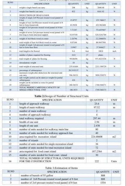
The design procedure is divided in to five parts and tabulated in the tables below.
Table I .Design of Single Structural Unit
SI.NO
SPECIFICATION QUANTITY UNIT QUANTITY UNIT
1 weight a single barrel can carry 208 kg 2040.48 N
2 weight four barrels can carry 832 kg 8161.92 N
3 DEDUCTIONS OF DEAD LOADS
4
weight of single 2x8 Pressure treated wood pannel of
8 feet 15.8757 kg 155.740617 N
5
weight of four 2x8 Pressure treated wood pannel of 8
feet to form framework 63.5028 kg 622.962468 N
6
weight of 2x4 pressure treated wood pannel of 8 feet
long 7.71107 kg 75.6455967 N
7
weight of seven 2x4 pressure treated wood pannel of 8
feet long to form structural support 53.97749 kg 529.5191769 N
8 weight of 4x4 block wood at corner 2.26796 kg 22.2486876 N
9 total weight of four 4x4 block wood at corner 9.07184 kg 88.9947504 N
10
weight of single 1x6 pressure treated wood pannel of 8
feet to form base floor 5.8967 kg 57.846627 N
11 total length to be floored 8.4 feet 100.8 inch
12 number of plates required for flooring 16.8 17 plates
13 total weight of plates for flooring 99.06456 kg 971.8233336 N
14 missalanious weight 10 kg
15 total weight of structural unit 235.61669 kg 2311.399729 N
16 percentage of submergence 28.3193137 %
17
maximum weight after deductions the structural unit
can carry 596.38331 kg 5850.520271 N
18
safe weight carried can be taken as weight for partial
submergance 416 kg
19
weight can be included as extra for partial
submergence 180.38331 kg 1769.560271 N
20
TOTAL WEIGHT CARRYING CAPACITY OF
SINGLE STRUCTURAL UNIT 180.3833 kg 1769.560173 N
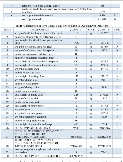
Table 2.Design of Number of Structural Units
SI.NO SPECIFICATION QUANTITY UNIT
1 length of approach walkway 25.6 m 2 length of main walkway 97.52 m
3 number of main walkway 2
4 number of approach walkway 4
5 total walkway required 297.44 m
6 bredth of one unit 2.56 m
7 length of one unit 2.438 m
8 number of units needed for walkway main line 80 9 number of units needed for walkway approach line 40
10 area required for recreation island 224.68608 m2
11 number of islands 2
12 number of units needed for single recreation island 36 13 number of units needed for total recreation island 72
14 area required for food court island 187.2384 m2 15 number of units needed for food court island 30
16
TOTAL NUMBER OF STRUCTURAL UNITS REQUIRED
FOR THE CONSTRUCTION 222 Units
Table 3.Estimation of Items
SI.NO SPECIFICATION QUANTITY UNIT
4 number of 4x4 block wood at corner 888
5
number of single 1x6 pressure treated wood pannel of 8 feet to form
base floor 3774
6 total rope required for one unit 4.576 M
7 total rope required 1015.872 M
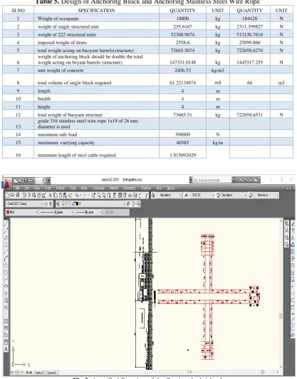
Table 4. Deduction of Live Loads and Determination of Occupancy of Structure
SI.NO SPECIFICATION QUANTITY UNIT QUANTITY UNIT 1 weight of artifitial flower pot and rubber plant 1.2 kg 11.772 N 2 number of flower pots and rubber plant units 63
3
total weight of artifitial flower pot and rubber
plant 75.6 kg 741.636 N
4 weight of sofa round back two piece 65 kg 637.65 N 5 weight of sofa round back three piece 90 kg 882.9 N 6 number of sofa round back two piece 10
7 number of sofa round back three piece 4
8 total weight of sofa round back two piece 650 kg 6376.5 N 9 total weight of sofa round back three piece 360 kg 3531.6 N 10 weight of rocking chair 45 kg 441.45 N 11 number of rocking chair 3
12 total weight of rocking chair 135 kg 1324.35 N 13 weight of dining table 30 kg 294.3 N 14 number of dining table 8
15 weight of dining chairs 6 kg 58.86 N 16 number of dining chairs 48
17 total weight of dining units 528 kg 5179.68 N 18 weight of ceramic sink 20 kg 196.2 N 19 number of ceramic sink 6
20 total weight of ceramic sink 120 kg 1177.2 N 21 weight of piano 140 kg 1373.4 N 22 weight of sump and pump 150 kg 1471.5 N 23 weight of lamp table and lamp 5 kg 49.05 N 24 number of lamp table and lamp 80
25 total weight of lamp table and lamp 400 kg 3924 N 26 TOTAL IMPOSED LIVE LOAD 2558.6 kg 25099.866 N
27
TOTAL LOAD CARRYING CAPACITY OF STRUCTURE FORMED BY
INTERLINKING 222 UNITS 40045.0926 kg 392842.3584 N
28
LOAD CARRYING CAPACITY OF STRUCTURE AFTER DEDUCTION OF
IMPOSED LIVE LOADS 37486.4926 kg 367742.4924 N
29
average weight of a single men in kerala is
assumed as 80 kg 784.8 N
30 TOTAL OCCUPANCY OF STRUCTURE 468.5811575
The occupancy result obtained is 468 people at a time for safety consideration and to meet drastic conditions, Half the occupancy of obtained value is considered, Hence the design occupancy is 234 people at a time.
Table 5. Design of Anchoring Block and Anchoring Stainless Steel Wire Rope
SI.NO SPECIFICATION QUANTITY UNIT QUANTITY UNIT
1 Weight of occupants 18800 kg 184428 N
2 weight of single structural unit 235.6167 kg 2311.399827 N
3 weight of 222 structural units 52306.9074 kg 513130.7616 N
4 imposed weight of items 2558.6 kg 25099.866 N
5 total weight acting on buoyant barrels(structure) 73665.5074 kg 722658.6276 N
6
weight of anchoring block should be double the total
weight acting on boyant barrels (structure) 147331.0148 kg 1445317.255 N
7 unit weight of concrete 2406.53 kg/m3
8 total volume of single block required 61.22134974 m3 64 m3
9 length 4 m
10 bredth 4 m
11 height 4 m
12 total weight of buoyant structure 73665.51 kg 722658.6531 N
13
grade 316 stainless steel wire rope 1x19 of 26 mm diameter is used
14 maximum safe load 398000 N
15 maximum carrying capacity 40585 kg/m
16 minimum length of steel cable required 1.815092029
Fig 3. Auto Cad Drawing of the floating dock island
IV.
CONCLUSIONS
The study leads to find innovative ideas to creatively utilize the upstream region of regulator cum bridges. The effective utilization of the static water body conveniently promote the tourism possibilities and in turn the economy of the locality.Adoption of floating dock islands enhance the effective utilization of static water. The design of the island is accomplished in an ecofriendly way and the floating structure provide the sunlight passage to the water body effectively due to the type of design.Hence the structure will not hamper the aquatic ecosystem. Required amount of factor of safety is adopted time to time through each steps thus the structure have sufficient serviceability to withstand in the drastic conditions and eccentric loadings too.
REFERENCES
[1]. Levathes, Louise (1994). When China Ruled the Seas. Oxford University Press. p. 77. ISBN 978-0-19-511207-8.
[2]. Needham, Joseph (1986). Science and Civilization in China: Volume 4 Part 3. Taipei: Caves Books, Ltd. Page 660
[3]. Sarton 1946, p. 153. [4]. Sarton 1946, pp. 153f.
[5]. "Meyer WerftbautgrößteDockhalle der Welt". Spiegelonline. 2008-01-18. Retrieved 2009-06-25. [6]. "North America's largest drydock floats first ship at Swan Island's Vigor Industrial (infographic and
time lapse)". OregonLive.com. Retrieved 2016-11-03.
[7]. Noel, John V. (1988). Knight's Modern Seamanship (18 ed.). John Wiley and Sons. pp. 81–82. ISBN 0-471-28948-5.
[8]. Photos of USS Samuel B. Roberts on blocks in AFDB-3 in 1988
[9]. "Sea Going Navy Yard Follows The Fleet", November 1945, Popular Science
[10]. www.engineeringtoolbox.com