e-ISSN: 2278-067X, p-ISSN: 2278-800X, www.ijerd.com
Volume 12, Issue
6
(
June
2016), PP.41-46
High-Speed Parallel Vlsi Architecture For Golay Decoder
Algorithm
Ashima Dubey
1, Dr. Rita Jain
2, Prof. Soheb Munir
31Student, Department Of ECE Lakshmi Narain College Of Tech. Bhopal, India 2Head Of Department Of ECE Lakshmi Narain College Of Tech. Bhopal, India 3
Professor, Department Of ECE Lakshmi Narain College Of Tech. Bhopal, India
Abstract: -
An efficient algorithm and the VLSI-architecture for fast soft-decision permutation decoding of the (24,12) extended Golay code are presented. The new decoding technique consists of an optimized permutation decoding with kogge stone parity weight measurement. The idea is to implement a fast parallel decoder to correct the most common error patterns (single and double adjacent) and use a slower serial decoder for the rest of the patterns. In this brief, it is shown that the same scheme can be efficiently implemented for the (24,12,8) Golay code. In this case, the properties of the Golay code can be exploited to implement a parallel decoder that corrects single- and double-adjacent errors that is faster and simpler than a single-error correction decoder. The binary Golay code (G23) and extended binary Golay code (G24) are implementation in Spartan-3, Virtex-2 and Virtex-2p high speed with low-latency architecture.Keywords: -
Binary Golay Code (23, 12, 7), Extended Golay Code (24, 12, 8), Kogge Stone Adder, Weight Measurement Unit.I.
INTRODUCTION
With the rapid growth of digital communications, such as Digital Audio Broadcasting (DAB) and ATM systems, increased data rate and advanced error control coding techniques are required. Thus, the parallelism inherent in the decoding algorithm and the area-efficient high-speed VLSI architectures must be exploited. The (24,12,8) extended Golay code is a well- known error-correcting code, which has been successfully applied in several existing communication systems to improve the system bit-error-rate (BER) performance. One goal of this research was to provide a strong error protection for the important head information in the transmission of the high quality compressed music signal of the DAB system. The parallel Golay decoder can be, of course, used generally to protect the data transmission or storage against channel errors for high speed data processing. A number of soft-decision decoding of the (24,12) binary Golay code were intensively investigated in the last few years and detailed analysis of computational complexity were discussed. However, none of these algorithms have been realized efficiently with parallel VLSI circuits. This paper introduces a full parallel permutation decoding technique with look-ahead error-correction and a fast soft-decision decoding for (24, 12, 8) extended Golay code. The area-efficient parallel VLSI architectures and the computer simulation results are also presented.
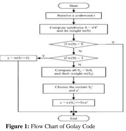
Figure 1: Flow Chart of Golay Code
II.
COLAY CODE
The Binary Golay code is represented as (23, 12, 7) that depicts that length of codeword is 23 bits, while message is of 12 bits and the minimum distance between two binary Golay codes is 7.
1 0 0 0 1 1 1 0 1 1 0 1 0 0 0 1 1 1 0 1 1 0 1 1 0 0 1 1 1 0 1 1 0 1 0 1 0 1 1 1 0 1 1 0 1 0 0 1 1 1 1 0 1 1 0 1 0 0 0 1 1 1 0 1 1 0 1 0 0 0 1 1 1 0 1 1 0 1 0 0 0 1 1 1 0 1 1 0 1 0 0 0 1 1 1 1 1 1 0 1 0 0 0 1 1 1 0 1 1 0 1 1 1 1 1 1 1 1 0 1 0 1 1 1 1 1 1 1 1 0 1 1 1 1 1 1 1 1 1 1 0 1 1 0 A
A Galois field (GF) is necessary to construct binary codes. In general, binary field is denoted by GF (2), which supports different binary arithmetic operations. The generation of coding sequence needs a generator polynomial. The possible generator polynomials [13] over GF (2) for Golay (23, 12, 7) code are x11 + x10 + x6 + x5 + x4 + x2 + x1 and x11+x9+x7+x6+x5+x1+1. In this brief, AE3h is considered as the characteristic polynomial. The remainder of the long division gives the required check bits. Finally, appending the generated check bits with the message gives us the extended Golay codeword. The extended Golay code (24, 12, 8) can be generated by appending a parity bit with the binary Golay code or using a generator matrix G, which is defined as [I, B], where I denotes an identity matrix of order 12.
III.
Encoder And Decoder
The first byte of the ROM code is a cyclic redundancy check. If a Golay code is calculated from the following 12 message bits, then agreement with this value implies that the ROM code is error-free. Although this does not have to be used in simple applications.
Figure 2: Block Diagram of Encoder for Golay Code
Figure 3: Decoder for Golay code
IV.
EXTENDED GOLAY CODE
There are two closely related binary Golay codes. The extended binary Golay code, G24 (sometimes
just called the "Golay code" in finite group theory) encodes 12 bits of data in a 24-bit word in such a way that any 3-bit errors can be corrected or any 7-bit errors can be detected. The other, the perfect binary Golay code, G23, has codewords of length 23 and is obtained from the extended binary Golay code by deleting one
coordinate position (conversely, the extended binary Golay code is obtained from the perfect binary Golay code by adding a parity bit). In standard code notation the codes have parameters [24, 12, 8] and [23, 12, 7].
V.
PROPOSED ARCHITECTURE FOR ENCODER AND DECODER GOLAY CODE
1.
Syndrome Measurement Unit:Syndrome S is evaluated performing multiplication of received code word cw with parity check matrix H. Therefore, the logical expression for calculating MSB bit of syndrome vector is given as follows:
]
0
[
]
2
[
]
6
[
]
7
[
]
8
[
]
10
[
]
11
[
]
23
[
]
11
[
cw
XOR
cw
XOR
cw
XOR
cw
XOR
cw
XOR
cw
XOR
cw
XOR
cw
S
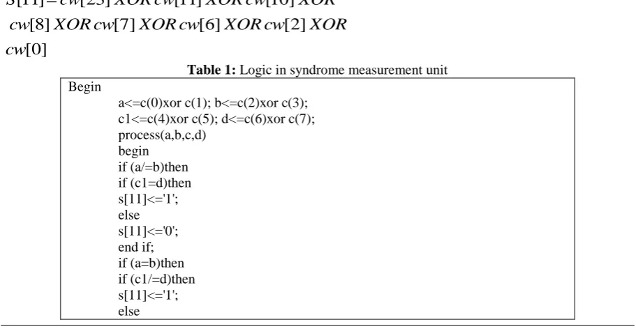
Table 1: Logic in syndrome measurement unit Begin
a<=c(0)xor c(1); b<=c(2)xor c(3); c1<=c(4)xor c(5); d<=c(6)xor c(7); process(a,b,c,d)
s[11]<='0';
end if; end if; end if; end process;
Table 2: Comparison result for syndrome unit Spartan-3
Architecture Slice LUTs Delay Satyabrata Sarangi et al. [5] 2 out of 768 3 out of 1536 9.064 nsec Proposed Architecture 1 out of 768 1 out of 1536 8.104 nsec Virtex-2
Satyabrata Sarangi et al. [5] 2 out of 256 3 out of 512 6.238 nsec Proposed Architecture 1 out of 256 1 out of 512 5.508 nsec Virtex-2p
Satyabrata Sarangi et al. [5] 2 out of 1408 3 out of 2816 5.700 nsec Proposed Architecture 1 out of 1408 1 out of 2816 5.065 nsec
2.
Weight Measurement Unit:The weight measurement unit primarily counts the number of binary 1 in the sequence, which can be efficiently done by the circuit shown in Fig. 4, which results in less critical path delay.
Table 3: Comparison result for weight measurement Spartan-3
Architecture Slice LUTs Delay
Satyabrata Sarangi et al. [5]
11 out of 768 19 out of 1536 13.069 nsec
Proposed Architecture 10 out of 768 18 out of 1536 11.823 nsec Virtex-2
Satyabrata Sarangi et al. [5]
11 out of 256 19 out of 512 9.106 nsec
Proposed Architecture 10 out of 256 18 out of 512 8.139 nsec Virtex-2p
Satyabrata Sarangi et al. [5]
11 out of 1408 19 out of 2816 8.205 nsec
Proposed Architecture 10 out of 1408 18 out of 2816 7.350 nsec
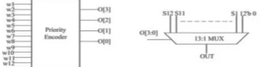
3. Multiplexer unit:
After performing for all the 12 registers, we get 12 bits as output. These bits are then fed to a 12:1 priority encoder as inputs and subsequently a 13:1 multiplexer is used to select the desired register content, which has satisfied the weight constraint. The four output of the priority encoder serves as the select signal for the multiplexer.
FA
FA
FA
FA
2-bit KS Adder 2-bit KS Adder
3-bit KS Adder
4-bit
Figure 4: Structure of Weight Measurement
Table 4: Comparison result for 13:1 Multiplexer Spartan-3
Architecture Slice LUTs Delay
Satyabrata Sarangi et al. [5] 4 out of 768 8 out of 1536 10.286 nsec Proposed Architecture 4 out of 768 6 out of 1536 10.065 nsec Virtex-2
Satyabrata Sarangi et al. [5] 4 out of 256 8 out of 512 7.132 nsec Proposed Architecture 4 out of 256 6 out of 512 6.765 nsec Virtex-2p
Satyabrata Sarangi et al. [5] 4 out of 1408 8 out of 2816 6.466 nsec Proposed Architecture 4 out of 1408 6 out of 2816 6.104 nsec
In this way, after performing for all the 12 registers, we get 12 bits as output. These bits are then fed to a 12:1 priority encoder as inputs and subsequently a 13:1 multiplexer is used to select the desired register content, which has satisfied the weight constraint. The four output of the priority encoder serves as the select signal for the multiplexer.
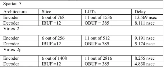
Table 5: Result for proposed Encoder and Decoder Spartan-3
Architecture Slice LUTs Delay Encoder 6 out of 768 11 out of 1536 13.569 nsec Decoder IBUF =12 OBUF = 385 8.111 nsec Virtex-2
Encoder 6 out of 256 11 out of 512 9.191 nsec Decoder IBUF =12 OBUF = 385 5.174 nsec Virtex-2p
Encoder 6 out of 1408 11 out of 2816 8.255 nsec Decoder IBUF =12 OBUF = 385 4.830 nsec
All the designing and experiment regarding algorithm that we have mentioned in this paper is being developed on Xilinx 6.1i updated version. Xilinx 5.2i has couple of the striking features such as low memory requirement, fast debugging, and low cost. The latest release of ISETM (Integrated Software Environment) design tool provides the low memory requirement approximate 27 percentage low. ISE 6.1i that provides advanced tools like smart compile technology with better usage of their computing hardware provides faster timing closure and higher quality of results for a better time to designing solution. ISE 6.1i Xilinx tools permits greater flexibility for designs which leverage embedded processors. The ISE 6.1i Design suite is accompanied by the release of chip scope ProTM 6.1i debug and verification software. By the aid of that software we debug the program easily. Also included is the newest release of the chip scope Pro Serial IO Tool kit, providing simplified debugging of high-speed serial IO designs for Virtex-2 FX and Virtex-2P LXT and SXT FPGAs. With the help of this tool we can develop in the area of communication as well as in the area of signal processing and VLSI low power designing.
VI.
CONCLUSION
Efficient hardware architecture for both binary Golay encoder and extended binary Golay encoder have been designed and implemented after verifying the proposed algorithm. The results obtained from simulation state that the proposed hardware architecture for encoder supersedes the conventional LFSR-based CRC generation schemes. Similarly, the proposed hardware module for decoder shows better performance to some of the recent publications considering various performance metrics. These hardware modules for encoder and decoder can be a good candidate for various applications in high speed communication links, photo spectroscopy, and ultrasonography.
REFRENCES
[1]. Ayyoob D. Abbaszadeh and Craig K. Rushforth, Senior Member, IEEE, “VLSI Implementation of a Maximum-Likelihood Decoder for the Golay (24, 12) Code”, IEEE Journal on Selected Areas in Communications. VOL. 6, NO. 3, APRIL 1988.
[2]. W. Cao, “High-speed parallel VLSI-architecture for the (24, 12) Golay decoder with optimized permutation decoding,” in Proc. IEEE Int. Symp. Circuits Syst. (ISCAS), Connecting World, vol. 4. May 1996, pp. 61–64. [3]. W. Cao, “High-speed parallel hard and soft-decision Golay decoder: Algorithm and VLSI-architecture,” in Proc.
IEEE Int. Conf. Acoust., Speech, Signal Process. (ICASSP)., vol. 6. May 1996, pp. 3295–3297.
[5]. Satyabrata Sarangi and Swapna Banerjee, “Efficient Hardware Implementation of Encoder and Decoder for Golay Code”, IEEE Transactions On Very Large Scale Integration (VLSI) Systems 2014.
[6]. B. Honary and G. Markarian, “New simple encoder and trellis decoder for Golay codes”, ELECTRONICS LETTERS 9th December 1993 Vol. 29 No. 25.
[7]. Michael Sprachmann, “Automatic Generation of Parallel CRC Circuits”, 0740-7475/01/$10.00 © 2001 IEEE. [8]. Giuseppe Campobello, Giuseppe Patane`, and Marco Russo, “Parallel CRC Realization”, IEEE TRANSACTIONS
ON COMPUTERS, VOL. 52, NO. 10, OCTOBER 2003.
[9]. Xiao-Hong Peng, Member, IEEE, and Paddy G. Farrell, Life Fellow, IEEE, “On Construction of the (24, 12, 8) Golay Codes”, IEEE Manuscript received January 19, 2005; revised July 7, 2005 and December15, 2005, respectively.
[10]. G. Solomon, “Golay encoding/decoding via BCH-hamming,” Comput. Math. Appl., vol. 39, no. 11, pp. 103–108, Jun. 2000.
[11]. I. Boyarinov, I. Martin, and B. Honary, “High-speed decoding of extended Golay code,” IEE Proc. Commun., vol. 147, no. 6, pp. 333–336, Dec. 2000.
[12]. D. C. Hankerson et al., Coding Theory and Cryptography The Essentials, 2nd ed. New York, NY, USA: Marcel Dekker, 2000.
[13]. M.-H. Jing, Y.-C. Su, J.-H. Chen, Z.-H. Chen, and Y. Chang,“High-speed low-complexity Golay decoder based on syndromeweight determination,” in Proc. 7th Int. Conf. Inf., Commun., Signal Process. (ICICS), Dec. 2009, pp. 1–4. [14]. T.-C. Lin, H.-C. Chang, H.-P. Lee, and T.-K. Truong, “On the decoding of the (24, 12, 8) Golay code,” Inf. Sci., vol.