GENERATING TEST CASE BY USING USE
CASE OBJECT ORIENTED METHODS
Anil Pandey1 and Muslima Aslam2
I. INTRODUCTION
Software testing is an important activity in software development life cycle. Software organizations spend large portion of their budget in testing related activities. Software Testing is a costly and time consuming process in software development life cycle. Automation of this phase may lead to overcome the above problems and also reduces the human effort in other ways it also helps in detecting the human intended errors and logical errors as well. The Automation of testing will not be that much productive in terms of cost and time consuming because if we have to wait till the end of the Software Development Life Cycle stage (SDLC). Software Testing[1] is any process or activity aimed at evaluating a system or attribute or capability of a program and determining through the purpose to find that whether it satisfies or meets the specified requirements or not. In simple words testing is executing a system in order to discover any
1
Department of computer Sc. &Engg Invertis University U.P, India
2
Department of computer Sc. &Engg Invertis University U.P, India
DOI: http://dx.doi.org/10.21172/1.81.008 e-ISSN:2278-621X
Abstract: In software testing is an crucial part of software development in the number of verification and validation process of the software. In an object oriented method we must have to apply the method of mapping the software for all its transition states and the number of the output for a set of given input. For a any given part of software we will be writing a set of test cases that called test suites and test place it is used to group together similar test cases. Test suites is a collection of test cases that are planned to be used to test an object oriented method to illustrate that it has some specific set of behaviors. In order to find out how a test case is valid or not for that we do not have specific mechanism. We mostly depend on the software testers understanding of the requirement. In my paper study UML diagrams different technique by using use case in test cases, for example test case generation using test case generation using random based testing, test case generation using Model based testing. The test cases are derived by analyzing the dynamic test of the objects due to external and internal stimuli.
errors, gaps or missing requirements in contrary to the actual requirements desire output
Figure1: Software Testing Steps
Test cases help the user to pen down entire coverage to the application and test all possible combinations in the application. It also provides the user to easily reproduce the steps that were undertaken to uncover a defect that as detected during test. It also provides the extent of which the testing has concluded and the areas in which the application is working fine. Throughout the years a huge number of different technique have been proposed for generating test cases. A test case is basically a description of a test. A Test case has the components that describe an input, event or action and expected response to determine if the feature of an application is working correctly. Test cases can be mapped directly to. Test cases are derived from use cases and can also be derived from system requirements. The one of the main advantages of generating test cases from requirements specifications and design will often help the software or test engineer to discover problems as early. As they can be created earlier in the development life cycle and get ready for use before the programs are constructed. Generating test cases early helps Software Engineers or test engineer can often find ambiguities and inconsistencies in the requirements specification and design documents. This will absolutely take down the cost of building the software systems as errors are eliminated early during the life cycle. The below diagram[1] highlights the steps of software testing.
II. RELATED WORK
gave justification how these entities might evolved, the object diagram specified an initial configuration. The second component was also written in UML, was the test directive. This test directive consists of particular state and object diagrams, the object diagrams were used to state coverage criteria and test constraints; the state diagrams were used to identified test purposes. The test directives and system model be able build using any of the standard toolsets like Rational Rose.
T.Y. Chen et al. [5] developed a choice relation framework for supporting category-partition test case generation. All the constraints among choices must be defined manually. They captured the constraints among choices in rigorous and systematic manner via the introduction of various relations. The framework included the following features like consistency checks of specified constraints among choices, automatic deductions of new constraints among choices whenever possible, and a more effective test frame construction process. Category Partition Method (CPM) was a specification-based testing method that helps the software testers to formed test cases through refining the functional specification of a program into test specifications. They enable the software tester to specified the relative priorities for choices that were used for the subsequent formation of complete test frames. These test frames can subsequently be used as the basis for generating test cases. They applied their approach to real-life situations and reported on the efficiency of consistency checks and automatic deductions of choice relations. Franck Fleurey [6] presented a complete and automated chain for test cases derivation from formalized requirements in the perspective of object-oriented embedded software. However to automate the test generation process, there was huge space to bridge between high level use cases and concrete test cases. The test cases are generated into 2 steps. Use cases orderings are deduce from use case contracts, and that use case scenarios are substituted for each use case to generate test cases. Their purpose was to generate test cases for powerfully detecting faults in embedded s/w and is to cover the system in terms of statement coverage with those generated tests.
It has already known that software testing is one of the most important and critical phase of software development life cycle assuring the verification and validation process of the software. Testing of software requires a great deal of planning and resources as it is a time-consuming activity. The software testing immensely depends on three main phases: test case generation, test execution, and test evaluation. Test case generation is the core of any testing process and automating it saves much time and effort as well as reduces the number of errors and faults. According to a survey on various object oriented testing techniques for generating effective test cases is presented. For example test case generation using genetic algorithm, using UML sequence diagram, using UML activity diagrams, Scenario based test case generation etc.
leads to automation that reduces the human effort in finding bugs and errors. Automation in the last phase of system development is similar to manual testing. In both cases bugs are detected only after code has been complete. So rectifications and modification of the code takes lot of time. So testing process should be started from the beginning phase of software development life cycle and should continue till the last phase. For this it is proposed to generate test cases for object oriented software using UML diagrams like Sequence diagram. Test cases are optimized using the evolutionary algorithm, Genetic Algorithm.
Model-based test case generation is gaining acceptance to the software practitioners. Advantages of this are the early detection of faults, reducing software development time etc. In recent times, researchers have considered different UML diagrams for generating test cases. Few work on the test case generation using activity diagrams is reported in literatures. However, the existing work consider activity diagrams in method scope and mainly follow UML 1:x for modeling. According to, we present an approach of generating test cases from activity diagrams using UML 2:0 syntax and with use case scope. We consider a test coverage criterion, called activity path
coverage criterion. The test cases generated using our approach are capable of detecting more
faults like synchronization faults, loop faults unlike the existing approaches.
We present a comprehensive test case generation technique from UML models. We use the features in UML 2.0 sequence diagram including conditions, iterations, asynchronous messages and concurrent components. In our approach, test cases are derived from analysis artifacts such as use cases, their corresponding sequence diagrams and constraints specified across all these artifacts. We construct Use case Dependency Graph (UDG) from use case diagram and Concurrent Control Flow Graph (CCFG) from corresponding sequence diagrams for test sequence generation. We focus testing on sequences of messages among objects of use case scenarios. Our testing strategy derives test cases using full predicate coverage criteria.
Our proposed test case generation technique can be used for integration and system testing accommodating the object message and condition information associated with the use case scenarios. The test cases thus generated are suitable for detecting synchronization and dependency of use cases and messages, object interaction and operational faults. Finally, we have made an analysis and comparison of our approach with existing approaches, which are based on other coverage criterion through an example.
III. USE CASE & TEST CASE
In object-oriented software, the complexity of the software is not only associated with functions and procedures but also with how the procedures and classes are connected and how objects communicate. In this section, we have described the UML and related UML diagrams used in this paper for test case generation.
diagrams are used to model the static aspects of the different elements in the system, whereas behavioral diagrams focus on the dynamic aspects of the system. Our test generation methodology uses information present in two diagrams, namely use case and sequence diagrams. A use case comprises different possible sequences of interactions between the user and the computer. Each specific sequence of interactions in a use case is called a scenario. Sequence diagrams describe how a set of objects interact with each other to achieve a behavioral goal. UML 2.0 introduces the concept of a combined fragment [8] to capture complex procedural logic in a sequence diagram.
A use case is an abstraction of a system response to external inputs. It accomplishes a task that is important from user’s point of view [10]. Thus, a use case focuses on only those features visible at the external interfaces of a system. A use case instance defines particular input values and expected results. Use case diagrams do not present architectural models, user-interface models or workflow models. Use case lacks following necessary elements of test design:
1. Domain definition of each variable that participates in a use case.
2. Required input/output relationships among use case variables (called parameters). 3. Sequential constraints among use cases.
Use case scenarios are usually not executed in arbitrary orders. Some use case scenarios need to be executed before others. They may have <<extend>> and <<include>> dependencies as well as sequential dependencies which stem from the logic of the business process that the system supports. Hence, data comes in or goes out of the system through use cases. An actor gives input and receives output information through use cases. Thus, we can have dependencies and constraints between use cases for each actor. So use case diagrams can be ornamented with extra ad-hoc information to show relationships and dependencies among use cases of a system [11]. The Use Case formats described so far, are all versions of Use Case descriptions. Now we describe UML Use Case diagrams in detail. A more thorough description of UML Use Case diagrams can be found in (Fowler, 2003).
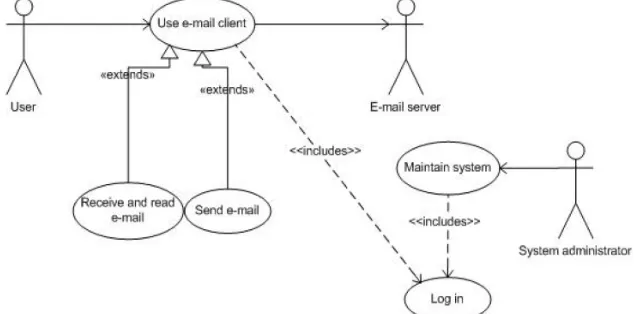
UML Use Case diagrams consist of actors and use cases (ellipses) which are connected by a link or a specific relation. The most common relations, in addition to the normal links, are «include», «extend» and generalization. Figure 2 illustrates a Use Case with normal links and the «include» and «extend» relation.
Figure 2: Example of a Use Case diagram with «include» and «extend»
variation on normal behavior. Generalization is used when we have a use case that is similar to another use case but does a bit more, (Fowler, 2003).
The use of «include» and «extend» relations is a highly debated topic. There exist several opinions on how to use the relations, and whether they should be used at all. People seem to have problems with understanding «include» and «extend», and with separating the relations from each other because of similar notational symbol and meaning. It is therefore wise to reduce the number of «include» and «extend». It is recommended to concentrate on the «include» relation, and avoid the «extend» relation completely, (Cockburn, 2001).
To make a diagram more comprehensible, the higher level goals, namely the base use cases (ellipses), should be drawn higher than the included or extended use cases. This is intuitive to readers, and the arrow from a base use case to an included use case will always point down. To reduce the difficulty of separating the two relations, Cockburn suggests to use another arrow than the default UML drawing for «extend». The default is a dashed arrow (the same as «include») with the phrase «extend» along side it. By instead drawing an arrow that is completely different from the «include» arrow, one highlight the difference between the two, making it easier to understand, (Cockburn, 2001).
Test Case: A test case is a set of test inputs, execution conditions, and expected results developed for a particular objective: to exercise a particular program path or verify compliance with a specific requirement, for example.
The purpose of a test case is to identify and communicate conditions that will be implemented in test. Test cases are necessary to verify successful and acceptable implementation of the product requirements (use cases).
We will describe a three-step process for generating test cases from a fully detailed use case: 1. For each use case, generate a full set of use-case scenarios.
2. For each scenario, identify at least one test case and the conditions that will make it "execute." 3. For each test case, identify the data values with which to test.
Test Case generation using a combination of use case Diagrams 1 Test Case 1
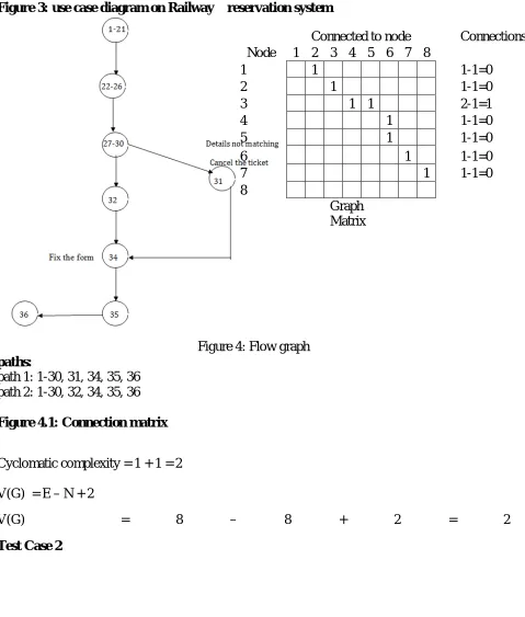
Figure 3: use case diagram on Railway reservation system
Figure 4: Flow graph
paths:
path 1: 1-30, 31, 34, 35, 36 path 2: 1-30, 32, 34, 35, 36
Figure 4.1:Connection matrix
Cyclomatic complexity = 1 + 1 = 2
V(G) = E – N + 2
V(G) = 8 – 8 + 2 = 2
Test Case 2
Connected to node Connections Node 1 2 3 4 5 6 7 8
1 1 1-1=0 2 1 1-1=0 3 1 1 2-1=1 4 1 1-1=0 5 1 1-1=0 6 1 1-1=0 7 1 1-1=0 8
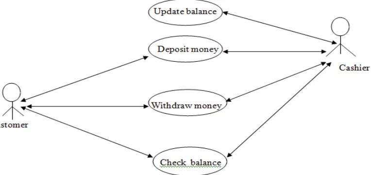
Figure 5: use case diagram on ATM Transactions
THE FLOW GRAPH
A flow graph of the ATM Transactions is shown below. You can think of this graph as a mathematical abstraction of the original program.
Figure5: Flow graph
paths:
path 1: 1, 2, 3-17, 25-27, 28
path 2: 1, 2, 3-17, 18, 19-20, 21-22, 23-24, 28 path 3: 1, 2, 3-17, 18, 28
Cyclomatic complexity = 2 + 1 = 3
V(G) = E – N + 2
Test Case 3
V(G)=10–
9+2=3 Connected to node Connections
Node 1 2 3 4 5 6 7 8 9
1 1 1-1=0
2 1 1-1=0
3 1 1 2-1=1
4 1 1 2-1=1
5 1 1-1=0
6 1 1-1=0
7 1 1-1=0
8 1 1-1=0
9
Figure 6: use case diagram on Inventory of items in a store
THE FLOW GRAPH
A flow graph of the Inventory of items in a store is shown below. You can think of this graph as a mathematical abstraction of the original program.
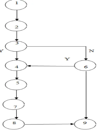
Figure6: Flow graph
path 1: 1, 2, 3, 4, 5, 7, 8, 9 path 2: 1, 2, 3, 6, 4, 5, 7, 8, 9 path 3: 1, 2, 3, 6, 9
Connected to node Connections
Node 1 2 3 4 5 6 7 8 9
1 1 1-1=0 2 1 1-1=0 3 1 1 2-1=1 4 1 1-1=0 5 1 1-1=0 6 1 1 2-1=1 7 1 1-1=0 8 1 1-1=0 9
Graph Matrix
Figure6.1:Connection matrix
Cyclomatic complexity = 2 + 1 = 3 V(G) = E – N + 2
V(G) = 10 – 9 + 2 = 3
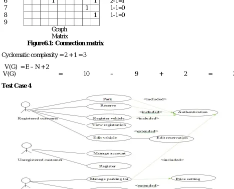
Test Case 4
Figure 7: use case diagram on Vehicle parking system
Figure7: Flow graph
paths: path 1: 1, 2, 3, 5, 7, 9,10 path 2: 1, 2, 3, 4, 8, 7, 9, 10 path 3: 1, 2, 3, 5, 6, 10 path 1: 1, 2, 3, 5, 7, 9, 8, 7, 9,10
Figure7.1:Connection matrix
Cyclomatic complexity = 3 + 1 = 4 V(G) = E – N + 2
V(G) = 12 –10+ 2 = 4
Result
Test case
No. of use case
No. of use case testing
1 10 2
2 6 3
3 7 3
4 16 4
IV. CONCLUSION
Connected to node Connections
Node 1 2 3 4 5 6 7 8 9 10
1 1 1-1=0 2 1 1-1=0 3 1 1 2-1=1 4 1 1-1=0 5 1 1 2-1=1 6 1 1-1=0 7 1 1-1=0 8 1 1-1=0 9 1 1 2-1=1 10
We generate test cases by using use case diagrams directly from object oriented methods, where the design is reused. By using our approach defects in the design model can be detected during the analysis of the model itself. So, the defects can be removed as early as possible, thus reducing the cost of defect removal. First we generate test case generation using use case diagrams, random based testing, model based testing and test scenarios from the activity diagram and then for each scenario the corresponding sequence diagram generated .After analyzing each category, its significant values and constraints are generated and respective test cases are derived. Test coverage criteria achieved is another advantage of our approach.
ACKNOWLEDGEMENT
This work was supported by Anil Pandey sir (Assistant professor). I would like to thanks to him for the continual encouragement, help and guidance throughout the work.
REFERENCES
[1]. Antonia Bertolina, “Software Testing Research and Practice”, Proceedings of the Abstract state machines
10th international conference on advances in theory and practice. [2]. Phases-of-testing-life-cycle.html
[3]. Rudnick Elizabeth M., Greenstein Gary S., “A Genetic Algorithm Framework for Test Generation” IEEE
Transactions on Computer Aided design of Integrated Circuits and Systems, VOL. 16, NO. 9, 1997. [4]. Cavarra, A., C. Crichton, J. Davies, A. Hartman, T. Jeron and L. Mounier. Using UML for automatic test
generation. Oxford University Computing Laboratory, Tools and Algorithms for the Construction and Analysis of Systems, TACAS 2000.
[5]. T.Y. Chen, Pak-Lok Poon and T.H Tse," A choice Relation Framework for supporting category-partition Test case Generation", IEEE Transactions on software engineering Vol. 29, No.7, 2003.
[6]. Clementine Nebut, Franck Fleurey, Yves Le Traon and Jean-Marc Jeze quel, "Automatic Test Generation: A Use Case Driven Approach", IEEE Transactions on software engineering Vol.32, No.3, 2006.
[7] G. Booch, J. Rumbaugh, and I Jacobson. “The Unified Modeling Language User Guide”, Object Technology Series Addision Weslley, 1999.
[8] OMG, “Unified Modeling Language Specification (v2.0),”2004.
[9] OMG, “UML 2.0 OCL Specification,”2004.
[10] R.V Binder. “Testing Object-Oriented Systems Models, Patterns, and Tools”. Object Technology Series. Addision Wesley, Reading, Massachusetts, October 1999.