ב ד"ס
Speed of Reflected Electromagnetic Waves
Copyright © 2016 by Moshe N Eisenman
Acknowledgment
I would like to express my sincere gratitude to my daughter Liat-Miriam for her effort and patience in preparing the graphs for this article.
Abstract
This paper demonstrates that the results analysis of Albert Abraham Michelson’s moving mirrors experiment is wrong. The conclusion that the speed of reflected light rays from the moving mirrors is not affected by the speed of the mirrors cannot be deduced from the data presented in Michelson’s paper.
There are several experiments that seemingly prove the second postulate of the theory of special relativity. One of them is Albert Abraham Michelson’s 1913 moving mirrors experiment. Another is the 1887 Michelson-Morley experiment. While the objective of the Michelson-Morley experiment was to measure the ether wind speed, the failure of which left everyone surprised and led to some far reaching conclusions, the Michelson moving-mirrors experiment was designed specifically to decide whether the speed of reflected light is affected by the speed of reflecting mirrors. Michelson’s unequivocal conclusion was that the speed of light rays is not affected by the motion of the mirrors, which is seemingly an experimental verification of Einstein’s second relativity postulate. We will show that Michelson was wrong to assume that the delay between two collinear light rays could cause an interference pattern and to equate this spatial delay to the observed distance between two adjacent constructive interference lines. Therefore, the question whether the moving mirrors affect the speed of light rays reflected from them cannot be answered based on the data presented in Michelson’s paper which reviews his moving mirrors experiment.
There are many arguments that invalidate (each one of them) the conclusions of the Michelson-Morley experiment. We will apply the argument used in the previous paragraph. The anticipation to observe an interference pattern was based on the premise that a spatial delay between two collinear light rays, caused by the ether wind, can produce such a pattern. Since this premise is wrong – all the conclusions of this experiment are invalid, including the refutation of the existence of ether.
Table of Contents
Chapter Title Page
Introduction 79
Nomenclature 80
1 Speed of Reflected Electromagnetic Waves 81
2 Review of Michelson’s Moving Mirrors Experiment
2.1 Introduction
2.2 Three Cases EM Wave Interaction
2.3 Michelson’s 1913 Moving Mirrors Experiment 2.4 Michelson-Morley 1887 Experiment
84
84 85 91 99
Appendix Required Accuracies in Assembling the Experiment Setup
100
Conclusion 107
Introduction
Over a time period of more than a century many experiments were performed to “prove” the postulates of the theory of relativity and its conclusions. In reference 3 it is proven that the theory of relativity is based on an error and is thus invalid. An experimental validation of any postulate or conclusion of the theory of relativity will not validate this theory, but rather invalidate the basic laws of electromagnetism (Ampere’s, Faraday’s and both Gauss’s laws).
The 1913 Michelson’s moving mirrors experiment was specifically designed to decide whether a moving mirror affects the speed of light reflected from it. The conclusion of this experiment was that the speed of the light rays reflected from the moving mirrors was not affected by their motion.
In chapter 1 of this paper it is shown, based on Maxwell’s equations, that the speed of a light ray reflected from a perfectly conducting reflector equals the speed of the approaching light ray, both with respect to the reflector. This, of course, contradicts the conclusion of Michelson’s experiment. In order to resolve this discrepancy an attempt was made to find an error in Michelson’s calculations, but none was found. A seemingly observed interference pattern is attributed by Michelson to a delay between two collinear light rays and the spatial delay is equated to the distance between two adjacent constructive interference lines. We will show that an observed interference pattern cannot be created by two collinear light rays, even in the case where there exists a delay between them. There are three contributions to the various observations of Michelson’s experiment. Michelson took into account two of them and neglected the angular motion of the mirrors. The angular motion does not affect Michelson’s calculated delay between two light rays, but it is the only cause of the lateral displacement between the two rays which causes an interference pattern. In addition we will show that the fact whether the motion of the mirrors affects, or does not affect, the speed of the reflected light rays has no (or very little) effect on the measured distance between two adjacent interference lines.
Nomenclature
ang The deflection angle of the moving mirrors from their position in figure 2.1 (positive clockwise)
Center Error The distance between the axis of rotation of the moving mirrors and the center of the cylindrical mirror
Closest Distance The smallest distance between a constructive interference line and the zero point
d Distance between the intersections of two split light rays on mirror A
(figures 2.1 and 2.2)
Effective Angular Deflection The range of the angle ang at which the light rays hit the moving mirrors EM Wave Electromagnetic Wave
h Distance of midpoint between the intersections of two split light rays on
mirror A and the zero point (figures 2.1 and 2.2)
Lateral displacement The distance between two parallel light rays, namely: in a direction normal to the direction of their propagation
Lower Point The point of intersection between the lower ray and mirror A or the monitoring screen
Lower Ray The light ray travelling on the route A, D, E, C, B and back to A and the monitoring screen (figure 2.2)
Monitoring Screen A screen on which optical phenomena are observed (figures 2.1 and 2.2) n Integer
p x/h
Plane Error The distance between the plane containing both moving mirrors from the axis or rotation
q 2
) (σ −τ
r The factor by which the speed of a moving mirror affects the speed of a Light ray reflected from it. r=0 or r=2
Upper Point The point of intersection between the upper ray and mirror A or the monitoring screen
Upper Ray The light ray travelling on the route A, B, C, E, D and back to A and the monitoring screen (figure 2.2).
x Distance from the zero point on the monitoring screen (figure 2.1) Zero Point The upper and lower points on the monitoring screen when they
coincide at ang=0
α The angle between mirror A and the monitoring screen (figure 2.1) φ λ/d
λ Light wave length σ (n+ξ)φ/cosα τ tanα
1.
Speed of Reflected Electromagnetic Waves
Based on Maxwell’s equations, it is proven in this chapter that the speed of a reflected electromagnetic (EM) wave from a perfectly conducting reflector equals the speed of the approaching wave, both relative to an observer which is stationary with respect to the reflector.
An EM wave hits a perfectly conducting plane normal to its surface at a speed v1,
amplitude of electric field a1, k1 =1/
λ
1 whereλ
1 is the EM wave length andϕ
1 is a given phase shift. What are the corresponding values of the reflected wave parameters [the parameters with subscript 2 in equation (1.1)]? Of particular interest is the value of v2, the speed of the reflected wave. Except for the phaseangles
ϕ
1 andϕ
2 -the values of all other parameters are assumed to be positive.The values of all the above parameters are as viewed by an observer stationary with respect to the reflector.
] ) ( cos[ ] ) ( cos[ ) ,
(x t =a1 k1 x −v1t +
ϕ
1 +a2 k2 x +v2t +ϕ
2E (1.1)
Let’s assume that the reflector is located at
x
=
l
. Due to the reflector being a perfect conductor we must have (in order to avoid infinite current densities):.
0
)
,
(
l
t
=
E
(1.2) Therefore: 0 ] ) ( cos[ ] ) ( cos[ ) ,(l t =a1 k1 l−v1t +
ϕ
1 +a2 k2 l +v2t +ϕ
2 =E (1.3)
for all t .
It follows from equation (1.3) that
E
(
l
,
t
)
and all its time derivatives must vanish.0 ] ) ( cos[ ] ) ( cos[ ) ,
(l t =a1 k1 l−v1t +
ϕ
1 +a2 k2 l +v2t +ϕ
2 =E (1.4)
0
]
)
(
sin[
]
)
(
sin[
)
,
(
l
t
=
a
1k
1v
1k
1l
−
v
1t
+
ϕ
1−
a
2k
2v
2k
2l
+
v
2t
+
ϕ
2=
E
&
(1.5)0
]
)
(
cos[
)
(
]
)
(
cos[
)
(
)
,
(
2 2 2 22 2 2 1 1 1 2 1 1
1
−
+
+
+
+
=
=
a
k
v
k
l
v
t
ϕ
a
k
v
k
l
v
t
ϕ
t
l
E
&
&
(1.6)From equation (1.6):
0 ] ) ( cos[ ] ) ( ) [( ]} ) ( cos[ ] ) ( cos[ { ) ( 2 2 2 2 1 1 2 2 2 2 2 2 2 1 1 1 1 2 1 1 = + + − + + + + + −
ϕ
ϕ
ϕ
t v l k v k v k t v l k a t v l k a v k (1.7)Since the first term in equation (1.7) vanishes according to equation (1.3):
1 1 2
2v kv
Equation (1.8) states that the frequencies of the oncoming and reflected waves, as viewed by an observer stationary with respect to the reflector, are equal.
From equations (1.4), (1.5) and (1.8):
] ) ( cos[ ] ) (
cos[ 1 1 1 2 2 2 2
1 k l −vt +
ϕ
=−a k l +v t +ϕ
a (1.9)
] ) ( sin[ ] ) (
sin[ 1 1 1 2 2 2 2
1 k l −vt +
ϕ
= a k l +v t +ϕ
a (1.10)
By adding the squares of the left and right hand side of the last two equations we obtain:
1
2 a
a = (1.11) Equation (1.11) states that since no energy is absorbed by the reflector – the amplitudes of the advancing and reflected waves’ electric fields are equal, and may thus be cancelled out from equation (1.1).
From equations (1.1) and (1.8):
] 2 ) ( ) ( cos[ ] 2 ) ( ) ( cos[ ] ) ( cos[ ] ) ( cos[ ) , ( 1 1 2 1 2 1 2 1 2 1 2 2 2 1 1 1 t v k x k k x k k t v x k t v x k t x E − − + − ⋅ + + + = + + + + − =
ϕ
ϕ
ϕ
ϕ
ϕ
ϕ
(1.12)At the location of the reflector,
x
=
l
:0 ] 2 ) ( ) ( cos[ ] 2 ) ( ) ( cos[ ) ,
(l t = k1 +k2 l + 1 + 2 ⋅ k1 −k2 l + 1 − 2 −k1v1t =
E
ϕ
ϕ
ϕ
ϕ
(1.13)The first cosine in equation (1.13) is not a function of time – which enables the fulfillment of the boundary condition (1.2) by the proper selection of the phase angle
ϕ
2.To determine the values of k2 and v2 we observe that the approaching EM wave [the first term on the right side of equation (1.1)] is a solution of the one dimensional Maxwell equation (1.14).
2 2 2 1 2 2 ) , ( ) , ( x t x E v t t x E ∂ ∂ = ∂ ∂ (1.14)
0 ] ) ( cos[ ] ) ( ) [( ] ) ( cos[ ] ) ( ) [( 2 2 2 2 1 2 2 2 2 2 1 1 1 2 1 1 2 1 1 1 = + + − + + − −
ϕ
ϕ
t v x k v k v k a t v x k v k v k a (1.15)The first term in equation (1.15) vanishes since, as explained above, it is a solution of the operator (1.14). From the second term of the last equation we obtain:
0 )
( 12
2 2 2
2 v −v =
k (1.16)
Hence:
1
2 v
v = (1.17)
And it follows from the last equation and (1.8) that:
1
2 k
k = (1.18)
Equations (1.17) and (1.18) state that, for an observer stationary with respect to a reflector, the speed and wavelength of a reflected EM wave equal those of the approaching wave. Substituting equations (1.17) and (1.18) into (1.12) yields:
] 2 ) ( cos[ ] 2 ) ( cos[ ) ,
( 1 2 1 2 1 1
1x kvt
k t
x
E = +
ϕ
+ϕ
⋅ϕ
−ϕ
− (1.19)This is a standing wave, which is a product of two functions: one varies only space-wise while the other varies only time-wise.
2. A Review of Michelson’s Moving Mirrors Experiment
2.1 Introduction
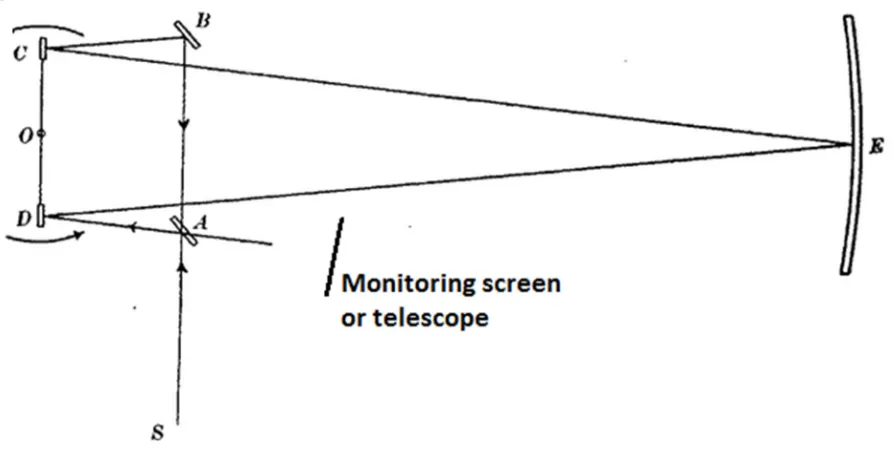
Michelson’s moving mirrors experiment is described in reference 1 and the two following links. These links are very much the same – except for somewhat different notations. The second link displays the location of the telescope where an interference pattern is supposedly observed.
https://en.wikisource.org/wiki/Effect_of_Reflection_from_a_Moving_Mirror_on_the_Velocity_of_Light http://www.angelfire.com/sc/aether/mic1913.html
There is a question whether the motion of a reflector influences the speed of an electromagnetic (EM) wave reflected from it. The objective of the above mentioned test was to decide this question experimentally.
We refer to the figure and notations of the first link (and figure 2 in section 2.3). A light ray from source S is split at the stationary lightly silvered mirror A and each of the resulting two rays travels over five legs and returns to mirror A. Over these five legs the two rays move in opposite directions. On the sixth leg, from mirror A to the telescope, they move in the same direction.
2.2 Three Cases EM Wave Interaction
Definition: The “lateral displacement” between two parallel EM waves is the distance between the lines of their motion, namely: in a direction normal to the direction of their propagation.
Case
#1:
Two EM waves (both having the same speedv
, wavelengthλ
and electric field intensity amplitudea
) move on the same line (or two parallel lines the relative lateral displacement of which is smaller than one wavelength). There is a phase shiftϕ
between them. The resulting electric field of the compositewave is: ) 2 cos( ) 2 cos( 2 )] cos( ) [cos( ) , (
ϕ
ϕ
λ
ϕ
λ
λ
− − = − − + −=a x vt x vt a x vt
t x
E (2.2.1)
The resultant wave is basically an “average” of the two original waves multiplied by an amplitude modification factor of
2
cos(
ϕ
/
2
)
. This means that theamplitude varies between the extremes of
2
a
and0
, depending on the value of the phase shiftϕ
. It is important to realize that there cannot be any interferencepattern in this case.
Case # 2:
Two EM waves (both having the same wavelengthλ
and electric field intensity amplitudea
, but have different speeds v1 and v2) move on the same line (or two parallel lines the relative lateral displacement of which is smaller than one wavelength).The resulting electric field of the composite wave is:
) 2 cos( ) 2 cos( 2 )] cos( ) [cos( ) , ( 2 1 2 1 2 1 t v v t v v x a t v x t v x a t x E
λ
λ
λ
λ
− + − = − + − = (2.2.2)The resulting wave propagates at the average speed (v1 +v2)/2 with a pulsating
Case #3:
Two EM waves (both having the same speedv
, wavelengthλ
and electric field intensity amplitudea
) move on two parallel lines the relative lateral displacement of which is greater than one wavelength.In figure 1 a light ray FA hits a lightly silvered mirror at the point A and is reflected towards a screen. Another light ray GB hits the mirror at the point B and goes
through it to the screen. In figure 1,
AB
=
d
,CD
=
h
andDE
=
x
.α
denotes the angle between the mirror and the screen. The point E is a constructiveinterference point if
AE
−
BE
=
n
λ
, whereλ
is the wavelength of the rays andn
is any integer. The last statement is valid only if the phases of the rays at theλ
α
α
α
α
h d x d h d nd
x− 2 + + 2 − + 2 + − 2 =
) sin 2 ( ) cos 2 ( ) sin 2 ( ) cos 2 ( (2.2.3)
Multiplying and dividing the left hand side of equation (2.2.3) by a similar term where the minus sign between the square-roots is replaced by a plus sign, and assuming that
d
<<
h
andd
<<
x
, we obtain:λ
α
α
n x h x h d = + ⋅ − ⋅ 2 2 2 ) cos sin ( 2 (2.2.4)Let’s define the following dimensionless parameters:
d h
x
p ≡ ;
φ
≡λ
(2.2.5)
Equation (2.2.4) becomes:
φ
α
α
n p p = + ⋅ − 2 1 cos sin (2.2.6)Now let’s assume that the phase difference between the two rays is known at point D on the screen where
p
=
0
. If the phase difference at that point is 0 - theinteger
n
of equation (2.2.6) must also vanish at that point, and the termsin
α
must be added to the right side of (2.2.6) in order for it to equate. In general there will be a phase difference between the rays at point D which may be characterized by a parameter
ξ
, which is the fraction of wavelength by which thelight ray FA leads the ray GB. The values of the parameter
ξ
are in the range5
.
0
5
.
0
<
≤
−
ξ
. In the more general case equation (2.2.6) becomes:α
φ
ξ
α
α
sin ) ( 1 cos sin2 = − +
+ ⋅ − n p p (2.2.7)
Dividing both sides of equation (2.2.7) by
cos
α
yields:The solution of equation (2.2.8) for
p
=
x
/
h
as a function ofn
provides thelocations x of the various constructive interference lines.
In order to facilitate the solution we define the following parameters:
α
τ
α
φ
ξ
σ
; tancos ) ( ≡ − ≡ n (2.2.9)
Equation (2.2.8) becomes:
τ σ τ + = + − 2 1 p p (2.2.10)
To solve equation (2.2.10) we square both of its sides. Since squaring adds extra solutions it is necessary to retain only the solutions that satisfy equation (2.2.10).
)
1
(
)
(
)
(
2 2 2p
p
=
+
+
−
σ
τ
τ
(2.2.11)
Rearranging we obtain:
]
)
(
[
2
]
)
(
1
[
2 2 2 2τ
σ
τ
τ
τ
σ
+
−
⋅
+
−
+
−
p
p
(2.2.12)Therefore: 2 2 2 2 2 ) ( 1 ] ) ( ][ ) ( 1 [
τ
σ
τ
σ
τ
τ
σ
τ
τ
+ − + − + − − ± = p (2.2.13)In the singular case where
(
)
21
=
+
τ
σ
, the solution forp
is the following:τ
τ
τ
σ
τ
σ
τ
τ
σ
τ
2 1 2 ) 2 ( 2 )( 2 2
2 − = + − = + − = p (2.2.14)
The condition for the existence of a solution is:
0
]
)
(
][
)
(
1
[
2 2 22
≥
+
−
+
−
−
σ
τ
τ
σ
τ
2
)
(
σ
+
τ
≡
q
(2.2.16) Equation (2.2.15) becomes:0
)
1
(
]
1
][
[
2 2 22
≥
−
+
=
−
−
−
τ
q
q
τ
q
q
τ
(2.2.17)
Wherefrom it follows that:
0
)]
1
(
[
2≤
+
−
τ
q
q
(2.2.18) Sinceq
≥
0
the condition for the existence of a solution is therefore:2
1
+
τ
≤
q
(2.2.19) It follows from the definition of the parameterq
in equation (2.2.16):2 2
1
1
+
τ
≤
σ
+
τ
≤
+
τ
−
(2.2.20) Thus:τ
τ
σ
τ
τ
−
≤
≤
+
−
+
−
2 21
1
(2.2.21) Inserting the values ofσ
andτ
in equation (2.2.9) into equation (2.2.21) yields:α
φ
ξ
α
)
(
)
1
sin
sin
1
(
+
≤
−
≤
−
−
n
(2.2.22) But sinceφ
=
λ
/
d
[see equation (2.2.5)]:ξ
λ
α
ξ
λ
α
+ ≤ ≤ − + +−(1 sin )d n (1 sin )d
(2.2.23)
Equation (2.2.23) provides the range of the integer
n
for which there exist solutions to equation (2.2.12). Ifξ
=
0
[ξ
is the fraction of wavelength by whichthe light ray FA leads the ray GB at point D (see figure 1)] n = 0 is in this range, and if
d
/
λ
<
0
.
5
this is the only point. It is easy to see that whend
/
λ
<
0
.
5
there are combinations of
ξ
andα
for which the range of the values ofn
inIn the case where
α
=0, which means that the mirror is parallel to the screen,0
=
τ
andσ
=
(
n
−
ξ
)
φ
, see equation (2.2.9):2 2 2 ] / ) [( 1 / ) ( ] ) [( 1 ) (
1 n d
d n n n p
λ
ξ
λ
ξ
φ
ξ
φ
ξ
σ
σ
− − − ± = − − − ± = − ± = (2.2.24)If, in addition, the phase shift between the two beams equals 0 (
ξ
=
0
. This is thecase of the classical interference experiment where two slits are illuminated symmetrically by a monochromatic light source) we have:
2 ) / ( 1 / d n d n p
λ
λ
− ± = (2.2.25)From equation (2.2.25) we see that in this symmetric case:
1. The interference pattern is symmetric.
2. The number of constructive interference lines is finite with
n
<
d
/
λ
.3. The distance between adjacent constructive interference lines is not constant. They are more crowded at the center of the interference pattern and become sparser at the edges.
4. If
d
/
λ
≤
1
there are no constructive interference lines, except for the one at the center.5. As
d
/
λ
increases – there are more constructive interference lines and they are more evenly spaced close to the center of the interference pattern. Ifλ
/
d
is very large – the constructive interference lines are very crowded and might appear as continuous line of light at the center of the interference pattern.6. The above closed-form analytical solution is valid only in case where
h
d
<<
andd
<<
x
. It seems that in the actual experiment these2.3 Michelson’s 1913 Moving Mirrors Experiment
As indicated in the above links this experiment was carried out with the purpose of deciding whether the motion of the mirrors affects the speed of light rays reflected from them (r=2) or whether it does not (r=0). The experiment results analysis led Albert Michelson to the seemingly indisputable conclusion that r=0. We will show that the results analysis is faulty and that the measured distance between two adjacent constructive interference lines is not affected by the speed of the reflected light rays from the moving mirrors. In other words – the measured distance is the same (or varies marginally) whether the moving mirrors affect the speed of the reflected light waves or if they do not.
“moving mirrors” are not rotating – the time spans it takes both rays to traverse the various legs are identical and will be referred to as the “nominal values”. When the “moving mirrors” are rotating – the above mentioned time spans differ from the nominal values and are not the same for both rays. Michelson computed the difference between the arrival times of both rays at the monitoring screen (in the original experiment it was a telescope), multiplied it by the nominal speed of light and divided it by the light wavelength. The result is the number of wavelengths by which one light ray arrives at the monitoring screen ahead of the other ray. Michelson equated this difference with the observed distance between two adjacent constructive interference lines.
The first attempt to review Michelson’s work was to check the veracity of his analysis. In order to avoid any doubt – a computer program was written, which is basically a ray tracing program, to compute the various variables associated with the experiment. The computations are absolutely accurate, no approximations whatsoever. In addition to the deviation from the nominal values of the travel time of both rays over the various legs, the program computes the coordinates of the intersection points between the rays and all the mirrors of the experiment setup, as well as the intersection points between the rays and the monitoring screen on which the interference pattern is observed.
There are three contributions to the above mentioned computed and measured variables:
1. The effect of the velocities of the moving mirrors. 2. The translational deviation of the moving mirrors. 3. The angular deflection of the moving mirrors.
In the computer program each contribution can be evaluated separately.
Seems that the conclusion of Michelson’s report is correct and the case is closed. Well, not quite.
A question arises: How is the observed interference pattern created? It certainly cannot be created due to the lag between the two light rays. While the above mentioned third contribution, namely: the angular deflection of the moving mirrors, does not affect the delay between the light rays, it turns out to be the only factor that causes them to hit mirror A at different points. Michelson neglected this contribution, accordingly on the final sixth leg the two rays must be travelling on the same straight line. As explained in case #1 of section 2.2 this lag can only affect the intensity of the light ray hitting the monitoring screen. It cannot create an interference pattern. Therefore, Michelson’s results analysis of his experiment is wrong.
The distance between two adjacent constructive interference lines in Michelson’s moving mirrors experiment is expressed in terms of the light wavelength. In case #3 of section 2.2 this same distance is expressed in terms of
p
=
x
/
h
, where h is the distance between the monitoring screen and the midpoint between the locations where the two light rays hit mirror A. Consequently, the comparison between the observed and computed locations of the interference lines is not straightforward. However, the computed distance between two adjacent constructive interference lines in case #3 of section 2.2 is independent (or varies very slightly as a function) of the value of the parameter r. Thus, the observed distance between two adjacent constructive interference lines is not indicative of the value of the parameter r. Therefore, the value of r cannot be determined based on the results presented in Michelson’s moving mirrors experiment article. However, repeating the experiment can render the value of the parameter r by observing the locations of constructive interference lines.Let’s define the “closest distance” as the distance between the zero point and the nearest constructive interference line, while the mirrors are rotating.
The mirrors should then be rotated. If the closest distance equals zero, namely: a constructive interference line is located on the zero point, then r=2. If the closest distance equals approximately a quarter of the distance between two adjacent constructive interference lines, and the corresponding constructive interference line is shifted towards the light source S in figure 2, then r=0. [See figure 6]
If the experiment is repeated – a laser beam should be used and the telescope of the original experiment can be replaced by a monitoring screen located relatively far away from mirror A (say 1.2m). In this case the assumptions that
d
<<
h
andx
d
<<
are valid along with all the derivations presented in section 2.2.The data presented in reference 1, as well as in the two links at the beginning of this chapter, provides the position of the moving mirrors C and D relative to the cylindrical mirror E (see figure 2). The exact positions of the stationary mirrors A and B are not specified. For the computations, the results of which are presented below, it was assumed quite arbitrarily that the distance travelled by the light ray between mirrors A and D, while stationary, is 0.3m. The results corresponding to two more values of this arbitrarily chosen distance are summarized below.
The four following figures present results obtained from the ray-tracing computer program runs, both for r=0 and r=2. Since the “calculated displacements” for r=0 and r=2 in Michelson’s paper equal 3.76 and 0, respectively, the corresponding values of
ξ
are -0.24 and 0. These results match the corresponding outputs of theray-tracing computer program, which in addition provides the following results:
63
.
5
/
λ
≅
d
andα
=
45
.
6242
o. The value ofh
=
1
.
2
m was arbitrarily selected. As explained above, the light ray emanating from source S is split at the lightly silvered mirror A. We first define the following two terms (see figure 2):1. Upper Ray: The light ray travelling on the route A, B, C, E, D and back to A and the monitoring screen.
The figures below pertain to the condition where the moving mirrors are rotating.
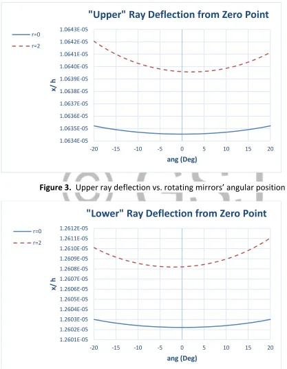
Figure 3. Upper ray deflection vs. rotating mirrors’ angular position
Figure 4. Lower ray deflection vs. rotating mirrors’ angular position
1.0634E-05 1.0635E-05 1.0636E-05 1.0637E-05 1.0638E-05 1.0639E-05 1.0640E-05 1.0641E-05 1.0642E-05 1.0643E-05
-20 -15 -10 -5 0 5 10 15 20
x
/
h
ang (Deg)
"Upper" Ray Deflection from Zero Point
r=0
r=2
1.2601E-05 1.2602E-05 1.2603E-05 1.2604E-05 1.2605E-05 1.2606E-05 1.2607E-05 1.2608E-05 1.2609E-05 1.2610E-05 1.2611E-05 1.2612E-05
-20 -15 -10 -5 0 5 10 15 20
x
/
h
ang (Deg)
"Lower" Ray Deflection from Zero Point
r=0
As indicated above, when the mirrors are not rotating both the upper and lower rays hit the same point on the monitoring screen, which is called the “zero point”, at any angular position of the moving mirrors.
Figures 3 and 4 present the normalized deviations of the upper and lower rays, respectively, from the zero point as a function of the angular deflection of the moving mirrors C and D relative to their position in figure 2 (a positive value of the angle ang means counter clockwise rotation).
It is apparent from figures 3 and 4 that these deviations are negligible, in view of the fact that the distance between two adjacent constructive interference lines is of the order of magnitude of
x
/
h
=
0
.
25
.Figure 5 presents the distance
d
between the upper and lower rays when hitting the mirror A on their way to the monitoring screen, divided by the lightwave-length
λ
( 0.6 10−6⋅ =
λ
m). As is obvious from the figure the variation ofd
/
λ
isless than 0.15% and has an insignificant effect on the interference pattern presented in figure 6. Accordingly, the value of
d
/
λ
corresponding tor
=
2
at0
=
ang
was arbitrarily selected for both curves in figure 6.5.6260 5.6270 5.6280 5.6290 5.6300 5.6310 5.6320 5.6330 5.6340
-20 -15 -10 -5 0 5 10 15 20
d
/
λ
ang (Deg)
(Distance Between Rays on Mirror A)/ (Wave Length)
r=0
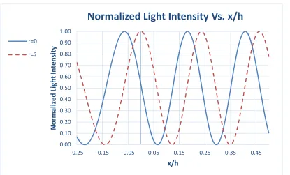
Figure 6 presents the interference patterns, only a limited regions near the zero point, for r=0 and r=2. Points where the normalized light intensity equals 1 or 0 correspond to constructive and destructive interference lines, respectively. In addition to the fact that an interference pattern is achieved for both r=0 and r=2, it is obvious that the distance between two adjacent constructive interference lines is practically the same for both values of r. The decision whether r=0 or r=2 can be made by measuring the “closest distance” defined above. If the closest distance equals zero, i.e.: a constructive interference line is located right on the zero point, then r=2. If the closest distance equals approximately a quarter of the distance between two adjacent constructive interference lines (it should actually
be close to the value of
ξ
=
0
.
24
) then r=0.Figure 6. Nominal interference pattern
As pointed out above, it was assumed quite arbitrarily that the distance travelled by the light ray between mirrors A and D in figure 2 is 0.3m. A rough estimate of this distance, assuming that figure 2 is drawn to scale, is 0.186m. The computation was repeated for the above mentioned rough estimate and for an exaggerated distance of 1.5m.
0.00 0.10 0.20 0.30 0.40 0.50 0.60 0.70 0.80 0.90 1.00
-0.25 -0.15 -0.05 0.05 0.15 0.25 0.35 0.45
N
o
rm
a
li
ze
d
L
ig
h
t
In
te
n
si
ty
x/h
Normalized Light Intensity Vs. x/h
r=0
If the distance travelled by the light ray between mirrors A and D in figure 2 equals 0.186m or 1.5m, the values of the normalized deflections in figures 3 and 4 should be multiplied by the factor 0.933 or 1.785, respectively. These deflections are still negligible compared to the distance between two adjacent constructive interference lines. The values of
d
/
λ
in figure 5 should be multiplied by the factors 0.982 and 1.194, respectively. The normalized distancex
/
h
between two adjacent constructive interference lines will be inversely proportional to these factors. However, the decision whether r=0 or r=2 stays unaltered since it depends on the ratio between the “closest distance” defined above and the distance between two adjacent constructive interference lines, rather than on absolute locations.If notes taken during the moving mirrors experiment in 1913 by Michelson and his assistants are available – a look at them might answer the question about the location of the closest constructive interference line relative to the zero point. Otherwise a repetition of the experiment is necessary to determine the value of r.
I bet that if the experiment is repeated, a constructive interference line will be located right on the zero point, and will thus be an experimental refutation of Einstein’s second relativity postulate.
2.4 Michelson-Morley 1887 Experiment
The 1887 Michelson Morley experiment is presented in reference 2 and at the following link:
https://en.wikipedia.org/wiki/Michelson%E2%80%93Morley_experiment
This experiment is flawed as well. Again, the expected interference pattern is attributed to the time (or distance) delay between two light rays (see figure 4, last figure, at the above link) which is wrong reasoning as explained in section 2.2.
In figure 7 of the above link we can see that an interference pattern was observed, but the estimated ether speed was much less than expected. The question is, in view of the explanations in the previous section, how was an interference pattern created in the first place? The reason could be very simple. Inaccuracies in mounting the various mirrors caused the two light rays to hit the central mirror at two different points, thus obtaining two light sources which are a necessary condition for the establishment of an interference pattern. The less accurate the mounting of the mirrors – the larger the distance between the two rays which is translated to a closer distance between two adjacent interference lines. Since the speed of the ether wind was wrongly associated with this distance – less mirror-mounting accuracy was interpreted as slower ether wind. In fact, if all the mirrors were mounted with absolute accuracy there would be no interference pattern. In case of very accurate, but not perfect, mounting the estimated ether wind could be estimated as greater, even much greater, than the speed of Earth in its orbit around the Sun. However, the above reasoning does not explain the periodic variation with time of the estimated ether wind speed which was observed in the Michelson-Morley experiment (could it be due to the angular positions of the various mirrors being affected by the gravitation of the Sun and/or moon?).
Appendix:
Required Accuracies in Assembling the Experiment Setup
The analysis of Michelson’s 1913 moving mirrors experiment in section 2.3 assumed that the experiment setup was assembled with absolute accuracy. Consequently, while the moving mirrors are not rotating, both the upper and lower rays (defined just before figure 3) hit the monitoring screen at the same point for any angular positions of the stationary mirrors. This point is defined as the “zero point”. This fact can be proven trigonometrically, but the proof is not included in this article.
Interferometry is very powerful in displaying extremely small time differences due to the exceptionally small light wave length. However, this feature makes it very sensitive to assembly errors of the experiment equipment.
What happens if the setup is not absolutely accurate? In this case there would not be a zero point since the upper and lower rays usually hit the monitoring screen at two different points. The intersections between the upper and lower rays, with either the monitoring screen or mirror A, are defined as the “upper point” and “lower point”, respectively. In addition, the locations of these points depend on the angular position of the mirrors.
The following graphs pertain to r=2, but they are essentially the same also for r=0. The “zero point” referred to in these graphs is the point where both upper and lower rays hit the monitoring screen when the angular position of the moving mirrors is as shown in figure 2 at the beginning of section 2.3 (i.e.: ang=0).
We discuss here two sources of errors:
1. The distance between the plane containing both moving mirrors from the axis or rotation, which is defined here as the “plane error”. It is positive when the plane of the moving mirrors is displaced towards the cylindrical mirror relative to the axis of rotation, when ang=0.
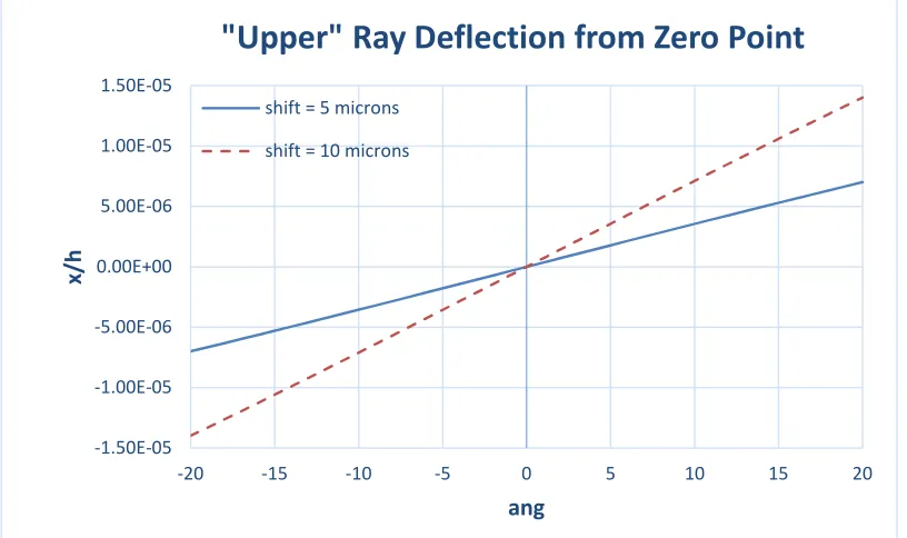
Figure 7. Plane error: upper ray deflection vs. stationary mirrors’ angular position
Figure 8. Plane error: lower ray deflection vs. stationary mirrors’ angular position
Figures 7 and 8 display the distance from the zero point of the upper and lower points, respectively, for two values of the plane error: 5 microns and 10 microns. This error is termed “shift” in the legends of the graphs.
-1.50E-05 -1.00E-05 -5.00E-06 0.00E+00 5.00E-06 1.00E-05 1.50E-05
-20 -15 -10 -5 0 5 10 15 20
x
/h
ang
"Upper" Ray Deflection from Zero Point
shift = 5 microns
shift = 10 microns
-1.50E-05 -1.00E-05 -5.00E-06 0.00E+00 5.00E-06 1.00E-05 1.50E-05
-20 -15 -10 -5 0 5 10 15 20
x
/h
ang
"Lower" Ray Deflection from Zero Point
shift = 5 microns
Although the values are significantly different from the perfectly accurate case (where they vanish), they are still negligible compared to the normalized distance between two adjacent constructive interference lines, which is of the order of magnitude of 0.25.
The real problem, in this case, is the distance (in terms of the light wave-length) between the upper and lower points on mirror A shown in figure 9. The variation is significant relative to the nominal value of about 5.63 when the mirrors are rotating and there are no assembly errors (see figure 5 and figure 15). In this case the number of interference lines and their locations vary significantly with the angular position of the moving mirrors, so that when the mirrors are rotating the interference pattern could come out fuzzy. This situation is unacceptable.
Figure 9. Plane error: distance between rays vs. stationary mirrors’ angular position
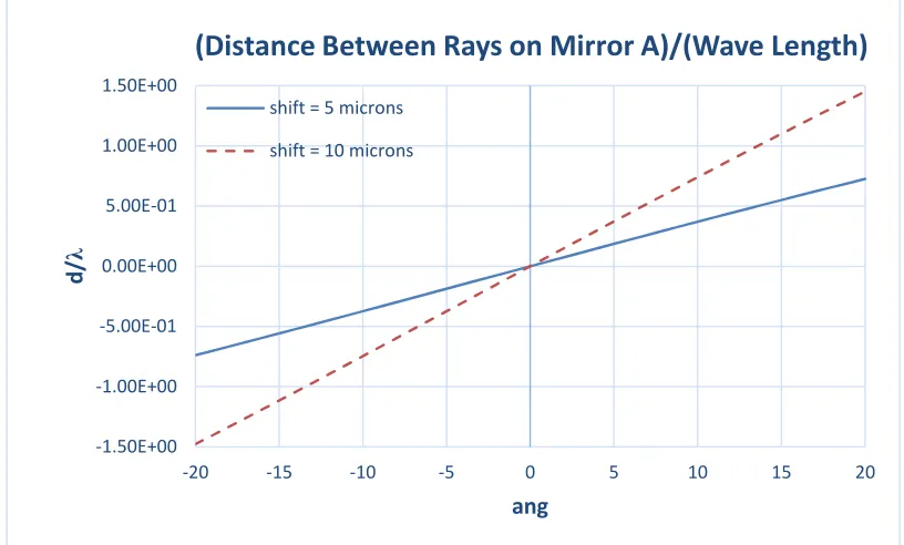
Figures 10 to 12 display the same kind of results as the above three figures, but in addition to the plane error an opposite center error is introduced (termed “joint error”). This means that when the plane error equals 5 and 10 microns, the center error equals -5 and -10 microns, respectively. These errors are termed “shift” in the legends of the graphs.
-1.50E+00 -1.00E+00 -5.00E-01 0.00E+00 5.00E-01 1.00E+00 1.50E+00
-20 -15 -10 -5 0 5 10 15 20
d
/
λ
ang
(Distance Between Rays on Mirror A)/(Wave Length)
shift = 5 microns
Figure 10. Joint error: upper ray deflection vs. stationary mirrors’ angular position
Figure 11. Joint error: lower ray deflection vs. stationary mirrors’ angular position
It is evident that the deviations of the upper and lower points are greatly reduced relative to those in figures 7 and 8. This is still not significant since all these deviations are negligible with respect to the distance between two adjacent interference lines.
-1.00E-06 -5.00E-07 0.00E+00 5.00E-07 1.00E-06
-20 -15 -10 -5 0 5 10 15 20
x
/h
ang
"Upper" Ray Deflection from Zero Point
shift = 5 microns
shift = 10 microns
-1.00E-06 -5.00E-07 0.00E+00 5.00E-07 1.00E-06
-20 -15 -10 -5 0 5 10 15 20
x
/h
ang
"Lower" Ray Deflection from Zero Point
shift = 5 microns
What is significant is the reduction of the distance between the upper and lower points on mirror A in figure 12 relative to that in figure 9. In this case the locations of the interference lines, when the mirrors are rotating, do not vary appreciably and the appearance of the interference pattern should be clear.
Figure 12. Joint error: distance between rays vs. stationary mirrors’ angular position
It is evident from the last six figures that the deviations of the distance between the upper and lower points caused by the plane error can be greatly reduced by introducing a corresponding center error, but cannot be totally eliminated. As expected, for a given maximum value of deviation – the angular range of the moving mirrors for the shift of 5 microns is larger than the corresponding angular range for the shift of 10 microns. Consequently, if the plane error is less than 10 microns – a corresponding center error can certainly be found and introduced so as to achieve a clear interference pattern when the mirrors are rotating. In addition, the moving mirrors assembly should be rigid enough and well balanced to avoid vibrations and the consequent blurring of the interference pattern.
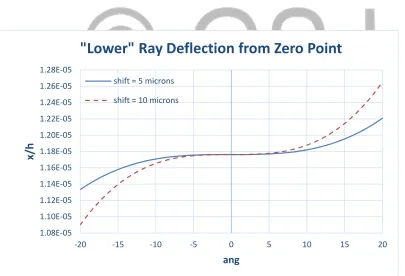
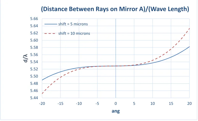
Figures 13 to 15 display the same kind of data as in figures 10 to 12, but for the case where the mirrors are rotating. The variation of
d
/
λ
(figure 15) by less than±1.8% is small enough for a clear interference pattern to be obtained.
-0.08 -0.06 -0.04 -0.02 0.00 0.02 0.04 0.06 0.08 0.10 0.12
-20 -15 -10 -5 0 5 10 15 20
d
/λ
ang
(Distance Between Rays on Mirror A)/(Wave Length)
shift = 5 microns
Figure 13. Joint error: upper ray deflection vs. rotating mirrors’ angular position
Figure 14. Joint error: lower ray deflection vs. rotating mirrors’ angular position
8.80E-06 9.00E-06 9.20E-06 9.40E-06 9.60E-06 9.80E-06 1.00E-05 1.02E-05 1.04E-05 1.06E-05 1.08E-05
-20 -15 -10 -5 0 5 10 15 20
x
/h
ang
"Upper" Ray Deflection from Zero Point
shift = 5 microns
shift = 10 microns
1.08E-05 1.10E-05 1.12E-05 1.14E-05 1.16E-05 1.18E-05 1.20E-05 1.22E-05 1.24E-05 1.26E-05 1.28E-05
-20 -15 -10 -5 0 5 10 15 20
x
/h
ang
"Lower" Ray Deflection from Zero Point
shift = 5 microns
Figure 15. Joint error: distance between rays vs. rotating mirrors’ angular position
The measured distance between the upper and lower points on mirror A (using the telescope) can serve as a feedback for fine tuning the experiment setup by modifying the center error. The measurements for the fine tuning must be taken when the mirrors are not rotating.
The variation of Michelson’s test results by
±
16
%
, around the center of the range of the measured values, can be explained by the existence of a plane error and/or a center error which cause the distance between the upper and lower points to vary with the angular position of the rotating mirrors (these points, rather an interference pattern, were most probably observed by Michelson, as explained in the paragraph before last of the conclusions). If measurements were taken by means of photographs – then the angular position of the moving mirrors (at the times when photographs were taken) was most probably random and different for any measurement, and along with it the measured result. This is, of course, a guess since Michelson’s article does not detail the means by which measurements were taken.5.44 5.46 5.48 5.50 5.52 5.54 5.56 5.58 5.60 5.62 5.64 5.66
-20 -15 -10 -5 0 5 10 15 20
d
/λ
ang
(Distance Between Rays on Mirror A)/(Wave Length)
shift = 5 microns
Conclusion
The 1913 Michelson’s moving mirrors experiment was specifically designed to decide whether a moving mirror affects the speed of light reflected from it. The conclusion of this experiment was that the speed of light rays reflected from the moving mirrors was not affected by their motion. In this article we prove that the objective of the experiment cannot be decided based on the data presented in Michelson’s paper.
The present work was motivated by the results of chapter 1 that prove, based on Maxwell’s equations, that an ideal reflector moving with respect to an inertial coordinate system does affect the speed of an EM wave reflected from it, which contradicts the conclusion arrived at by Michelson in his above mentioned paper.
Michelson attributes the creation of an observed interference pattern to a delay between two collinear light rays and equates the spatial delay between them to the distance between two adjacent interference lines. We have shown that an observed interference pattern cannot be created by two collinear light rays, even in case where there is a delay between them.
We have also shown that there are three contributions to the various observations of Michelson’s experiment. Michelson took into account two of them and neglected the angular motion of the mirrors. The angular motion does not affect Michelson’s calculated delay between two light rays, but it is the only cause of the lateral displacement between them which is responsible to the creation of an interference pattern. In addition we have shown that the fact whether the motion of the mirrors affects, or does not affect, the speed of reflected light rays has a very small effect on the measured distance between two adjacent interference lines. Therefore, the effect of a moving mirror on the speed of a light ray reflected from it cannot be deduced from this measurement.
Similar arguments invalidate the conclusions of the 1887 Michelson-Morley experiment.
a reflected light ray is affected by the motion of the mirror and r=2. If, however, the closest constructive interference line is displaced from the zero point (in a direction towards the light source S in figure 2) by approximately one quarter of the distance between two adjacent constructive interference lines – the speed of a reflected light ray from a moving mirror is not affected by the motion of the mirror and r=0.
It has also been pointed out that, according to reference 3, the theory of relativity is based on an error and is thus invalid. Therefore, an experimental validation of Einstein’s second relativity postulate would not confirm the theory of relativity, but would rather invalidate Ampere’s, Faraday’s and both Gauss’s electric and magnetic laws.
Finally, I am stating my belief that the examination of notes left by Michelson and his assistants, or the repetition of Michelson’s 1913 moving mirrors experiment, will prove that the speed of a reflected light ray from a moving mirror is affected by the motion of the mirror and that r=2. This result will invalidate Michelson’s conclusion and will be an experimental refutation of Einstein’s second postulate of the theory of relativity.
On second thought – I am doubtful whether the phenomenon observed by Michelson in his moving mirrors experiment was indeed an interference pattern. The distance between two adjacent interference lines is not an absolute magnitude; it depends on the distance between two light sources and an observation screen. The assignment of an absolute value to the measured distance between two adjacent constructive interference lines might indicate that what was actually measured was the distance between the intersection points of the two light rays with mirror A. The computed value, in terms of the light wave length is (see figure 1):
d
/
λ
⋅
cos
α
=
5
.
63
⋅
cos(
45
.
6242
°
)
=
3
.
937
, fits nicely in the range 3.1-4.3 of the measured values. The variation of the measured data about the midpoint is±
16
%
. This is a relatively large spread and should be investigated. A possible explanation is a small inaccuracy in locating the rotation axis relative to the center of the cylindrical mirror and/or the location of the mirrors plane with respect to the rotation axis (“center error” and “plane error”, respectively, in the appendix).References
1. The Astrophysical Journal, An International Review of Spectroscopy and Astronomical Physics; Volume XXXVII, January-June 1913. Page 190.
https://babel.hathitrust.org/cgi/pt?id=mdp.39015013166304;view=1up;seq=15
2. Michelson, Albert A; Morley, Eduard W. (1887). “On the Relative Motion of the Earth and the Luminiferous Ether”. American Journal of Science 34; 333-345. 3. Eisenman, Moshe N. “Back to Galilean Transformation and Newtonian Physics,
Refuting the Theory of Relativity”.