Research Article
1
Open source based peripherals for automotive electronic
control unit
J.Pančík*, V.Beneš
Department of Informatics, Bank College - AMBIS, a.s., Praha , Nárožní 2600/9, 158 00 Praha 5, Czech Republic
Abstract
The aim was to develop an embedded system for educational purposes with functions of emulation of some peripherals which are intended for automotive electronic stability control unit (ESC ECU). Emulators of two key ECU peripherals were developed: one for four wheel speed sensors (both two and three current levels types) and second for electronic parking break (EPB) switch based on LIN bus. As real-time processors the Arduino Micro platform was chosen. The up level information system architecture is based on the web server (Raspberry Pi 3 platform) and web browser client and programming was done with JavaScript language for the client (AngularJS framework) and also for server (Node.js).
Keywords: EPB system; wheel speed sensor; LIN bus; Arduino; Raspberry Pi; Node.js.
Received on 22 December 2017, accepted on 25 April 2018, published on 19 June 2018
Copyright © 2018J.Pančík and V.Beneš, licensed to EAI. This is an open access article distributed under the terms of the Creative Commons Attribution licence (http://creativecommons.org/licenses/by/3.0/), which permits unlimited use, distribution and reproduction in any medium so long as the original work is properly cited.
doi: 10.4108/eai.19-6-2018.154825
on Scalable Information Systems
EAI Endorsed Transactions on
1. Introduction
This work presents educational tool for the teaching of modern trends in automotive electronics. The aim was to develop a embedded system with functions of emulation of some peripherals which are intended for automotive electronic control units (ECU, Electronic Control Unit). The ECU is surrounded with peripherals (e.g. by sensor and another hardware parts) and it interacts with their surroundings via car's buses (e.g. CAN, LIN, FlexRAY) or via cable harness and electromechanical systems (e.g. ignition switch or EPB switch). ECU system tests serve to test all required functions ECU. For operations of ECU during system tests is typical that these activities are consistent with the ECU in the car. It is necessary to emulate of ECU’s peripherals during systems tests. Therefore emulation of the ECU’s peripherals is not only suitable for educational use of the future technicians and engineers but it may also be useful for preparing of ECU system test. In next text is necessary to understand how differences are between simulation and emulation. A simulator is an environment which models but an emulator is one that replicates the usage as on the original device or system. Simulation is when you are replicating, by the means of software, the general behaviour of a system starting from a conceptual model. Emulation is when you are replicating, in a different system, how the original system actually internally works considering each function and their relations. In other words: simulation is based on a software implementation of a model where the internal functions of the original systems are not taken into consideration (for example a "flight simulator" does not have any "component" of an actual aircraft). Emulation is a replica of the internal system functions on a different host (for example on a microcontroller platform). Emulators can also be strictly hardware-based and is normally based on a partial or complete "reverse engineering" phase..
2. Analysis
2.1 Description of EPB system
Since the EPB was first launched in 2001 the number of its functions continues to rise significantly. Electric parking brake system (EPB) business is growing and it is closely related to the safety and comfort of passengers. The deployment of EPB systems from year to year increases, as seen in Fig. 1. The EPB offers by far more than the basic apply and release of a conventional parking brake. It interacts with several other driver assistance systems. The driver experiences the EPB system by its functions. He expects safety and reliability at low “costs of ownership” with a highly comfortable “look and feel”. The system supplier needs to translate these mainly subjective
expectations into physical
characteristics of the system and design its components against measurable targets. Figure 2 gives an overview of the EPB system with the functionality perceived by the driver on the one hand and the components with their technical characteristics on the other hand. The EPB system consists of the mechatronic actuators that generate the clamp force necessary to safely hold the vehicle, the conventional calipers that convert clamp force into brake torque, electronic hardware with the Electronic Control Unit (ECU), cable harness and switches and especially the control software providing the functions that the driver will experience. State of the art is to integrate the EPB control unit into one ECU in the car with name electronic stability control system (ESC ECU) [1]. On the market there are Original Equipment Suppliers (OES) - specific solutions as well as OES - independent combinations from different ECU ESC and EPB suppliers. The latter case is commonly called crosswise integration of products from different suppliers and it is dictated and originated in modern global market with automotive components. The integrated EPB system can be divided into two parts: (1) One part of the EPB system contains the parking brake actuator, the parking brake caliper and the actuation logic (Park Brake Control, PBC), (2) The second part of the EPB system, also called the host, contains the EPB power electronics and necessary peripherals and EPB controls the functions as a part of the ESC ECU’s embedded software. In crosswise integration projects the OES-EPB is responsible for the first part and the OES-ESC for the second part. The aims of this division are: (a) encapsulation of knowledge about particular components, (b) clearly defined areas of responsibility, (c) independent testing and approval of components from the different suppliers, (d) enabling manufacturer-specific levels of functionality of the individual components. The development and release of such integrated systems needs clear requirements for the interfaces and rules for collaboration between the development partners.
3 EPB Switch
Figure 2 Electric Parking Brake System [1]
2.2 Peripherals of Electronic Stability
Control (ESC ECU) with EPB functionality
The block diagram of the ECU with ESC EPB functionality is showed in Fig.3 [2]. According to it, there are two types peripherals for ESC ECU - peripherals connected to the car’s buses (CAN or FlexRAY) and peripherals directly connected to the ECU (wheel speed sensors and the EPB switch). The EPB classical electro-mechanical switch is connected to the ESC ECU with 6 wires (with states: default open, close, Fig.4) or with 8 wires (with AutoHold function). Four pieces of wheel speed sensors (WSS) are connected to the ESC ECU each with two wires and they communicate with ECU by using current signals (the principle of current loop).
CAN / FlexRAY communication
EPB SWITCH
Figure 3 ECU type ESC with EPB functions configuration, adopted from [2]
EPB SWITCH
2_POS
2_NEG 1_POS
1_NEG DEFAULT STATE
CLOSE OPEN EPB SWITCH
2_POS
2_NEG 1_POS
1_NEG
CLOSE STATE
CLOSE OPEN
IPBESC)
IPBESC)
IPBESC)
IPBESC)
EPB SWITCH
2_POS
2_NEG 1_POS
1_NEG
OPEN STATE
CLOSE
OPEN
LED LED LED
ECU SIDE ECU SIDE ECU SIDE
Figure 4 Three basic states of EPB electromechanical switch, adopted from [2]. OPEN state = RELEASE of brake, CLOSE state = APPLY of brake
3 Design and implementation
Wheel speed sensors (WSS) are components with analogue current output. Current signals are used for transmission of the information about the wheel speeds from reason the suppression of the influence of the fault signals WSS are produced as devices with 2 levels (2L) current outputs and with 3 levels (3L) current outputs [3] [4]. Therefore information about wheel position is encoded by two or three levels of current (7mA, 14mA and 28mA current levels). For determine of exact position of the wheel we need to know the wheel circumference and the number of magnets placed around the perimeter of the wheel. LIN (Local Interconnect Network) is a cost-effective and deterministic communication system for connecting ECUs with smart sensors and actuators. The EPB electromechanical switch is in our contribution modified by utilization of the LIN bus, see more in the US patent [5]. Instead normally 6 or 8 wires we use only 3 wires. The trends reducing of number of peripherals wires by utilization of LIN bus can be seen in all modern cars [6]. In our solution of peripherals emulator we tried to use a maximum amount of modern technology well known in the community of developers. We used hardware platforms as Linux based minicomputer – Raspberry Pi and as 8 bit AVR microcontroller for real time signal processing – Arduino Micro. The information system architecture is based on the web server and web browser client and programming was done in JavaScript language for the client (AngularJS framework [7]) and also for server (Node.js [8]).
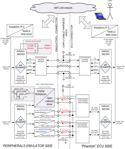
Fig.8 shows the architecture of the embedded system - right side represents the ECU ("Phantom" ECU side) and it consumes voltage and current signals from emulators at left side. The heart of each emulator’s part is Arduino Micro. The programs for all four Arduino's we developed in Arduino IDE environment which is enriched with many libraries and with like C programming language [9]. On the both sides the Arduinos work besides programs in main loop also with programs which were written in interrupt routines. Main loop ensures state machine control and I2C bus communication. Interrupts are derived from serial port
EAI Endorsed Transactions on
(RX or TX) or from internal timers and digital inputs. All distributed Arduino's are controlled via I2C bus from Raspberry Pi [10]. Both Raspberry Pi units have server’s role and they have installed Node.js [8]. This server's solution can be programmed with JavaScript language. It means that both sides, clients and servers, can be programmed with common JavaScript language. It includes not only programming of the web server but also the control of I2C hardware pins for Raspberry Pi at the I2C master side [11]. There are two client’s web sites in this embedded solution. One website serves for setting of parameters for peripheral emulation and another website serves for reading data captured at the ECU side. The developing of both client's web sites we done with utilization JavaScript-based open-source front-end web application framework AngularJS [7] and dynamic JSON data resources which represent inputs / outputs data ARDUINO's.
4 IMPLEMENTATION
4.1 WSS emulator
We emulate all four car's WSS with 2 or 3 levels current output signal. Computing power of Arduino Micro can serve only for two wheel’s pair emulating and it can't independent emulate of each WSS individually. Therefore we can emulate independent front wheels pair as two levels WSS and rear wheels pairs as three levels WSS (or vice versa). Current level pulses were generated via combination of digital controlled analog multiplexer as voltage level selector and open collector driver as voltage – current transformer. Two levels WSS (BOSCH DF11 and DF30, (see Fig.5)) can be offered with different signal protocols [3]. The "s" protocol is a square wave signal as rotary speed signal. The "i" protocol is a square wave signal with additional information which is transmitted in the pulse width modulation (PWM) protocol. The width of the square wave impulse includes additional information, while the time between one pulse and the next determines rotary speed information. The “v” protocol is a three level current signal that provides wheel speed information and additional information in a serial data protocol in accordance to the “AK-Protocol” [12]. The magnetic sensor on the wheels perimeter generates an output protocol after every detected magnetic signal flank, therefore its output signal frequency is twice as high as for the standard "s" protocol variant. At emulator’s ECU side we uses for detection current level pulses from each pair of WSS for ECU dedicated front–end device MAX9921 [13] and ARDUINO Micro (Fig.8) as device for real-time capturing logic level signals from front-end MAX9921. Arduino Micro also ensures I2C communication with up level Raspberry Pi 3 minicomputer. Fig.6 shows our real measurements of output current for emulation of DF11i in stop vehicle state (“standstill mode”).
Figure 5 Wheel speed sensors signal protocol type s, i, v [3]
4.2 EPB switch emulator
5 functional safety for LIN bus-based ECU peripherals according automotive function safety standard ISO 26262 is beyond scope of this paper [15].
4 Conclusion
This article deals with analysis, design and implementation of the equipment that is designed for emulation of signals dedicated as inputs for electronic stability control ECU. We developed emulators of two key peripherals: one for wheel speed sensors (both two and three current levels types) and second for EPB switch. The main goal of our work was developing an educational system which is based on modern open-source technologies. This embedded system is based on the state of art embedded server-client software solutions with JavaScript. Besides of these educational aims we try to coexist with modern automotive trends – alignment of high level functional safety requirements together with using of peripherals which are equipped with car’s buses. As illustration of these principles we proposed the EPB switch based on the LIN bus. Our possible contribution may be in the implementation of modern AUTOSAR network safety mechanism and parts of master/slave LIN bus state machines at open Arduino platform.
References
[1] REITZ, A. et all., "HARMONISATION OF THE RELEASE PROCESS FOR ELECTRIC PARKING BRAKE SYSTEMS," in Pub. FISITA, Proceedings of the EuroBrake 2016 Conference. 13-15 June 2016, Milan, Italy, 13-15 June 2016, MILAN, 2016.
[2] BOSCH, Encyclopedia of Automotive Engineering, John Wiley & Sons, Ltd., 2014.
[3] BOSCH, "DF30H Basic Technical Documentation Sensor DF30H," 2015.
[4] PHILIPS SEMI., "KMI22/1 Rotational speed sensor for extended air gap application and direction detection," 2000.
[5] US Patent 20080105502, "Electromechanical Parking Brake Device and Electronic System for Operating Same", 2008. [Online]. Available:
http://documents.allpatents.com/l/50722962/US200801055 02A1. [Accessed 13. March 2013].
[6] BMW, "E70 Voltage Supply and Bus Systems", 2010. [Online]. Available:
http://www.bmwmotorsports.org/pdf/e70/03a_E70%20Vol tage%20Supply%20and%20Bus.pdf. [Accessed 13. March 2013].
[7] "AngularJS," [Online]. Available: https://angularjs.org/. [Accessed 13. March 2017].
[8] "Node.js - JavaScript runtime built on Chrome's V8 JavaScript engine," [Online]. Available:
https://nodejs.org/en/. [Accessed 13. March 2017]. [9] "Arduino Micro," [Online]. Available:
https://www.arduino.cc/en/Main/arduinoBoardMicro. [Accessed 13. March 2017].
[10] "RASPBERRY PI 3 MODEL B," [Online]. Available: https://www.raspberrypi.org/products/raspberry-pi-3-model-b/. [Accessed 13. March 2017].
[11] “I2C interfacing Raspberry PI to Arduino," [Online]. Available: https://www.slideshare.net/MikeOchtman/i2c-interfacing-raspberry-pi-to-arduino. [Accessed 13. March 2017].
[12] CONTINENTAL, "Wheel Speed Sensor (WSS)," [Online]. Available:
http://www.continental-automotive.com/www/automotive_de_en/themes/commerc ial_vehicles/chassis_safety/speed_sensors/wheel_speed_se nsor_en.html. [Accessed 13. March 2017].
[13] MAXIM, "MAX9921 Dual, 2-Wire Hall-Effect Sensor Interface with Diagnostics," January 2010. [Online]. Available:
https://www.maximintegrated.com/en/products/analog/sen sors-and.../MAX9921.html. [Accessed 13. March 2017]. [14] AUTOSAR standard No.428 (release 4.2.2),
"Specification of SW-C End-to-End Communication Protection Library," AUTOSAR, 2015.
[15] FURST,S., BMW, "AUTOSAR and Functional Safety," 8. November 2011. [Online]. Available:
ttps://automotivetechis.files.wordpress.com/2013/04/autosa r-and-functional-safety1.pdf. [Accessed 13. March 2017]. [16] MOLKENTHIN,B., "CRC Calculator (Javascript),"
[Online]. Available:
http://www.sunshine2k.de/coding/javascript/crc/crc_js.htm l. [Accessed 17 March 2017].
[17] US Patent 7540213, ""Gearshift lever"," 2009. [Online]. Available:
http://www.freepatentsonline.com/7540213.html. [Accessed 13 March 2017].
[18] RASOOL,R.U. et al. A Study on Securing Software Defined Networks, International Conference on Web Information Systems Engineering, 479-489, 2017
EAI Endorsed Transactions on
Current probe TEKTRONIX TCPA300 Settings : 5A/V
Current direction
75 Ohm
(measurement resistor accor. by datasheet DF11i)
Open collector
driver Analog Multiplexer
Level 3 = 28mA Level 2 = 14mA
2
FRONT LEFT WSS
VBAT (TERMINAL 30)
IFront Left
Volatge / current factor: 1mV = 5mA
Digital control
Figure 6 Emulation of the WSS DF11i - standstill idle current pulse (zero velocity)
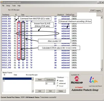
Command from MASTER (ECU side)
Answer from SLAVE (EMULATOR side)
Alive counter 0-F
Calculated CRC8 value (CRC-8-SAE J1850)
Enhanced checksum according LIN bus
7 WiFi LAN network
Arduino MICRO
Micro USB Arduino IDE debug/flash port
Raspberry Pi 3 Node.js Web sever
I2C Bus signals: I2C1-SDA I2C1-SCL GND
Raspberry Pi 3 Node.js Web sever
I2C Bus signals: I2C1-SDA I2C1-SCL GND Arduino MICRO Micro USB Arduino IDE debug/flash port Arduino MICRO Micro USB Arduino IDE debug/flash port Arduino MICRO Micro USB Arduino IDE debug/flash port RX TX ~CS ~RESET Vin LIN Transceiver Microchip MCP2025 LIN Transceiver Microchip MCP2025 RX TX ~CS ~RESET Vin
PERIPHERALS EMULATOR SIDE
“Phantom” ECU SIDE
Arduino TWI SDA,SCL Arduino TWI SDA,SCL Arduino TWI SDA,SCL Arduino TWI SDA,SCL VBAT (TERMINAL 30) GND (TERMINAL 31) LIN BUS DATA
LIN BUS GROUND LIN BUS POWER
Electronic Parking Switch
“OPEN” Position “CLOSE” Position Open collector driver Analog Multiplexer
Level 3 = 28mA Level 2 = 14mA Level 1 = 7mA R1
R2 R3
2
Open collector driver Analog Multiplexer 2
Open collector driver Analog Multiplexer 2
Open collector driver Analog Multiplexer 2 GND (TERMINAL 31) VBAT (TERMINAL 30) OE,~ERR, OUT1,OUT2
IFront Left
IRear Right
MAXIM MAX9921 Dual Hall Effect Sensor Interface
I Rear Left IFront Right
FRONT LEFT WSS
FRONT RIGHT WSS
REAR LEFT WSS
REAR RIGHT WSS
ECU C
O
N
NECTOR
WSS = Wheel Speed Sensor
USER
MAXIM MAX9921 Dual Hall Effect Sensor Interface
OE,~ERR, OUT1,OUT2
CAR’
s CABLE HAR
NESS AREA EMUL AT OR’ s CON NECTOR AVR ATmega32U4 AVR ATmega32U4 AVR ATmega32U4 AVR ATmega32U4
Figure 8 Blok diagram of the developed educational system for ECU peripheral's emulation
EAI Endorsed Transactions on
![Figure 1 EPB forecasted fitment EPB fitment rate [%] [1]](https://thumb-us.123doks.com/thumbv2/123dok_us/8427102.1696388/2.595.331.543.527.671/figure-epb-forecasted-fitment-epb-fitment-rate.webp)
![Figure 3 ECU type ESC with EPB functions configuration, adopted from [2]](https://thumb-us.123doks.com/thumbv2/123dok_us/8427102.1696388/3.595.69.223.91.247/figure-ecu-type-esc-epb-functions-configuration-adopted.webp)
![Figure 5 Wheel speed sensors signal protocol type s, i, v [3]](https://thumb-us.123doks.com/thumbv2/123dok_us/8427102.1696388/4.595.316.475.83.234/figure-wheel-speed-sensors-signal-protocol-type-s.webp)