ORIGINAL PAPER
Objective and subjective evaluation of an advanced
motorcycle riding simulator
Vittore Cossalter&Roberto Lot&Stefano Rota
Received: 27 April 2010 / Accepted: 2 November 2010 / Published online: 26 November 2010 #The Author(s) 2010. This article is published with open access at Springerlink.com
Abstract
Purposes This paper outlines the characteristics of a top-of-the range motorcycle simulator designed and built at the University of Padua over a period of several years last years; it consists of a motorcycle mock-up with func-tional throttle, brakes, clutch and gearlever mounted on a five‘degrees of freedom’platform, a real-time multibody model of the motorcycle and an audio and visual systems. The applications of the simulator are to test devices such as ABS, traction control and other ARAS in a controlled, safe environment, to study riders’behaviour and to train them. The aim is to find a procedure to validate the behaviour of a Motorcycle Riding Simulator with a real PTWs.
Methods An innovative procedure for the objective and subjective validation of motorcycle simulators has been developed and implemented, in order to be able to apply the results obtained on the simulator to the real world.
ResultsThe evaluation of objective and subjective data collected shows that the proposed simulator is adequate for handling tests. The proposed method is suitable to be extended to vehicle simulator in general.
ConclusionsThe development work done by University of Padova provides an innovative and reliable tool for the validation of a motorcycle riding simulator.
Keywords Motorcycle . Powered two wheelers (PTWs) . Simulator . Safety
1 Introduction
Nowadays, powered two-wheeler vehicles (PTW) are widely used not only for pleasure, but also for increasing mobility in the crowded urban and sub-urban roads of many European towns. For several reasons, PTW dynamics and safety have not been investigated as much as with four-wheeled vehicles, despite the fact that riders are among the most vulnerable road users. Therefore the development of devices aimed at improving the comfort and safety of PTWs, as well as investigating the behavioural factors that contribute to crashes, are important areas for research. Moreover, the roll degree of freedom which makes PTWs quick and prompt on urban roads and diverting on the rural track has some safety implications which require new riders to receive proper training. Unfortu-nately it is not easy to train new riders in dangerous situations, such as riding on a slippery road or emergency braking. From this point of view riding simulators may help both as a training tool and in the development of innovative devices aimed at improving rider safety.
It is worth noting that motorcycle riding simulators are not as widespread as aircraft and car driving simulators, and therefore the current selection is not very rich. Honda started to develop a series of motorcycle simulators in 1988; its first prototype consisted of a 5 DOF mock-up (lateral, yaw, roll, pitch and steer motions on a swinging system for the longitudinal acceleration restitution) and was based on a linear 4 DOF motorcycle dynamics model. In 1996, as a consequence of the change of the Japanese Road Traffic Act which required the use of simulators in riding schools lessons, Honda put a mass-produced model on the market. This second prototype had a simplified 3 DOF mock-up (roll, pitch and steer motions) and it was based on a properly tuned empirical motorcycle model. In 2002, Honda developed a third prototype which consisted of a 6 DOF plan manipulator for the mock-up motion, a head V. Cossalter
:
R. Lot (*):
S. RotaDepartment of Innovation in Mechanics and Management, University of Padova,
mounted display for visual projection, a 4 DOF model for the lateral motorcycle dynamics and a 1 DOF model for the longitudinal dynamics [1,2]. The Department of Innovation in Mechanics and Management (DIMEG) of Padua Univer-sity began the development of a riding simulator in 2000 and presented the first prototype in 2003 [3]. In 2003, PERCRO laboratory also presented its riding simulator with a real scooter mock-up mounted on a steward platform [4], and in 2007 INRETS presented a riding simulator based on a 5 DOF platform and a linear 5 DOF motorcycle mathematical model [5].
The DIMEG motorcycle simulator has been developed to test devices such as ABS, traction control and other ARAS in a controlled, safe environment, to study riders’ behaviour and to train them. It is possible to reproduce and consequently analyse the most critical and risky situations that a normal rider will find every day on all roads. However, in order to apply the results obtained by the studies on the riding simulator to a real motorcycle it is necessary that the behaviour of both simulator and motorcycle are the same. Since there are very few studies focussing on motorcycle simulators and in particular on their validation, this paper proposes an innovative proce-dure for both objective and subjective validation and reports the results of its application to the DIMEG simulator. Fine tuning and validation activities were performed inside the 2BeSafe project in the Seventh European Framework Programme (theme 7—sustainable surface transport), and commenced in January 2009. 2BeSafe is a collaborative research project and its objective is to conduct behavioural and ergonomic research in order to develop countermeasures for enhancing powered two-wheeler (PTW) riders’safety, including research into crash causes and human errors and the world’s first naturalistic riding study involving instrumented PTWs.
This paper first describes the DIMEG simulator, then explains the proposed validation methodology and illus-trates the data collected during objective and subjective evaluation.
2 Description of the riding simulator
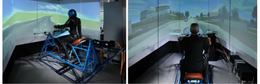
A simulator is a complex system that aims to reproduce a real environment in a restricted and controlled area where it is possible to simulate any actions under totally safe conditions. The motorcycle riding simulator shown in Fig.1 is a top of the range one and has been designed and developed in its entirety at DIMEG. On the simulator, the rider sits on a motorcycle mock-up and operates the throttle position, brakes, clutch and gearshift lever like on a real bike. Moreover, the handlebar and footpads are sensorized.
The rider’s control actions are transferred to the real-time multibody model of the motorcycle which has a 14‘degrees of freedom’model, includes a realistic model of the suspension, clutch, engine, tires and a 3-D road, and has been optimised for real-time performance. The simulated dynamics are then filtered by the washout and converted into references for the motion and visual cues. Motion cues are generated by the servomotors that drive 5 axes of the mock motorcycle; the roll, pitch, yaw and steer rotations plus the lateral displacement. The different subsystems are described in detail below.
2.1 Motorcycle mock-up
The rider rides a motorcycle mock-up equipped with all of the commands available on a real bike. In particular, the rider’s actions are monitored by measuring the steering torque, leaning of the body, throttle position, front brake lever and rear brake pedal pressures, clutch position and gearshift lever position.
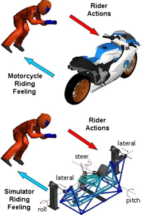
Figure2 shows the motion cues of a motorcycle mock-up whose serial kinematic chain is composed of 4 mobile frames plus a fixed one to reproduce the motion of the vehicle in terms of lateral displacement, yaw, roll, pitch and steer rotations. The first mobile member has the yaw and lateral displacement degrees of freedom, which are actuated by two servomotors equipped with ball screws; in sequence there are the roll, the pitch and steer degrees of freedom, as summarised in Figs.6,7and8.
The simulator includes an audio-visual system; in particular, the scenario is projected onto three widescreens measuring 1.5×2 m2placed in front of the rider. The 5.1 surround sound system reproduces engine sound previously recorded on a real motorcycle for a range of engine rpm.
2.2 Real-time multibody model
In order to achieve a good, realistic correspondence between a real and the simulated motorcycle a detailed multibody model was developed. The motorcycle model is composed of a whole motorcycle; its front frame, wheels and the rider’s upper body (see Fig.3).
The mathematical model is non linear and has 14 DOF (see Fig.3), corresponding to the position and orientation of the chassis, the steering angle, the front and rear suspension travels, the front and rear wheel rotations, the engine spin rate, the front fork bending deflection and the sprocket absorber deflection. There are 7 motorcycle inputs: steering torque, throttle position, rear and front brake torques, gears selected, clutch position and the foot pegs effort (as an indirect measure of the rider’s torso motion). Suspensions and tires are modelled in detail, as well as the clutch, the gearbox and the engine. More details are given in references [9,10].
2.3 Washout filter
Since it is physically impossible to reproduce accelerations as they are in real life using the simulator, a washout filter
is used, which aims to recreate riding accelerations and angular velocities by using the acceleration and the angular velocity of the simulator (inertial effect) and the tion of gravity (gravitational effect). Simulated accelera-tions are first separated by filters into their spectral components. The components at low frequencies are gener-ated using the gravitational effect, slowly tilting the simulator, while the components at high frequencies are reproduced by moving the simulator faster (with the electrical engine) and exploiting the effects generated by the inertial motion. As shown in Fig.4, this implemented washout is made up of two parts: the first filter (low pass filter), after an initial gauge, which removes high frequency components of input varia-bles and includes a matrix that combines the various inputs in a linear combination, and, after that, a second filter which provides the output for the platform.
It has been found that moving the simulator like a real motorcycle to the greatest possible extent does not give the best riding feeling, so gains and other adjustable parameters of the washout filter have been tuned using a trial-and-error procedure based on the subjective evaluation of feelings. Appropriate tuning leaded to a different washout for the visual and motion screens; as an example, while cornering, the roll angle is divided into two parts: the biggest one is used to tilt the virtual horizon on the screen, while a smaller part is used to give a motion cue by rolling the mock-up motorcycle. This solution is particularly useful while using the new visual system com-posed of three widescreens and a large field of view (FOV).
3 Simulator validation
3.1 Methodology
Motorcycle riding simulators are more recent than car and truck simulators, so they still need to be tuned to make them suitable for use in studies into rider behaviour. The challenge is to find an optimal compromise in the rendering of the simulator which allows the riders to feel as if they are riding an actual PTW and at the same time allows them to Motion cue parameters
Yaw ±20˚, ±0.20˚/s
Lateral motion ±0.3m, ±0.3m/s
Roll ±20˚, ±60˚/s
Pitch ±10˚, ±50˚/s
Steering ±20˚, ±50˚/s
Fig. 2 Motion cue capabilities of the UNIPD simulator
succeed in mastering the PTW as easily as they can master an actual one (at least for normal riding situations). To attain this goal, the following procedure has been iteratively applied: the first step is the fine-tuning of the motion, sound
and visual rendering devices, which has been done experimentally using a small group of highly skilled riders; the second step is the simulator validation, conducted by comparing the behaviours, performances and self-reported impressions of a wider group of riders of different ages, experience and skill. The validation, which of course is the most important aspect, is based on two complementary concepts: the objective validation, where some objective, carefully selected parameters are compared between mo-torcycle and simulator test sessions and the subjective validation, where the riding feeling is evaluated by means of the subjective rating of test subjects.
The aim of the validation process may be better understood by looking at Fig. 5. On the top, it shows the interaction between a rider and a motorcycle: the rider controls the motorcycle (by moving the handlebar, by actuating the throttle or by braking etc.), the result is the actual motion of the vehicle and then feedback is given to the rider in terms of motion, sounds and visual cues. On the bottom, it shows the interaction between a rider and a virtual motorcycle (i.e. a riding simulator) with the same kind of human-machine interaction as in real conditions (Figs.6and 7).
Since it is physically impossible to reproduce accelerations as they are in real life using the simulator, it is fundamental to use a washout filter and properly tune it. The washout tuning has been carried out by team members who are also expert riders and engineers involved in motorcycle dynamics. Tuning was performed with particular attention to:
& the perception of the speed;
& the braking feeling and the feeling while riding on bumpy roads;
& the feeling during transient cornering;
& the vehicle responsiveness during lane changes, over-taking and obstacle avoidance manoeuvres;
& the riding experience at low speed. Fig. 4 The washout filter
architecture
Besides the identification of the most suitable washout filter parameters, the tuning phase demonstrated that foot pegs control is very important for the improvement of rider feeling in transient motion and that the projection system using 3 widescreens greatly improved speed perception, even if it did increase simulator sickness.
After the completion of tuning, a final validation was conducted using a sample group of riders of different ages and levels of experience and skill. This was done by considering both objective and subjective data, as explained in detail in the next sections.
3.2 Objective evaluation
The objective evaluation consists of a comparison between the behaviour of the real and virtual motorcycles during the same riding actions. Despite the fact that there are many riding conditions with several uncontrolled parameters, the literature concerning the objective evaluation of motorcycle handling characteristics [7–27] helped us to focus on selected
manoeu-vres that are representative of the more general vehicle behaviour. In particular, the following three typical manoeuvres have been selected for the evaluation of the riding experience:
& Slalom (three different cone distances);
& Lane change (two different lane geometries);
& Steady turning (three radii);
The above manoeuvres are also part of the set of manoeuvres commonly used by motorcycle manufacturers to develop their own vehicles. Tests were carried out by two skilled riders. The motorcycle used for the tests was equipped with a special handlebar with steering torque and steering angle sensor, foot pegs with load cells, GPS and an inertial measurement unit with accelerometers and gyrometers.
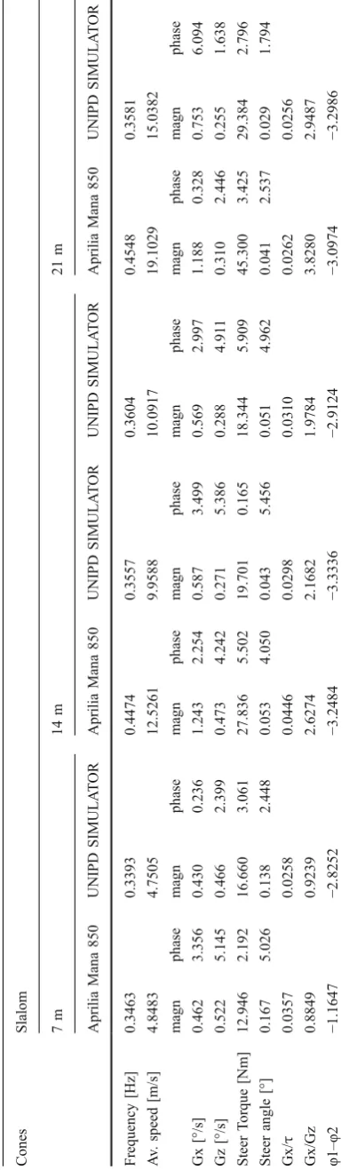
The slalom test was performed with three different distances between the cones on a straight line at established speeds.
For the sake of clarity, the results of both the simulator and motorcycle tests are presented in Table1, indicating the most relevant parameters. Since it is practically impossible to reproduce exactly the same manoeuvre, first on the motorcycle and then on the simulator, the comparison between real and simulated manoeuvres is more meaningful when based on the ratio Gx/τbetween the roll rate (which represents the vehicle behaviour) and the steering torque (which represents the rider action). Moreover, the ratio Gx/Gz between the roll and yaw rates and the phase lagϕ1ϕ2between the Gx phase and the steering torque gives additional information. As the cone distance increases from 14 m to 21 m the magnitude ratio decreases, whereas there are only small changes in the phase difference. This can be observed from the values in Table1.
Lane change manoeuvres may be classified by means of the width and length of the trajectory and vehicle speed, as shown in Fig. 8. In this case, tests have been performed using a lane width of 3 m and lengths of 14 and 21 m at speed range between 50 and 75 km/h. The manoeuvre can start from the right side and finish on the left side of the cones (right to left lane change) or the reverse. In addition, Steering
torque
Steering GPS, 3 axis gyro
Fig. 6 The UNIPD instrumented motorcycle
in this situation the speed should be kept constant as much as possible.
In the lane change manoeuvre the rider exerts some controlling action (torque) causing the vehicle to roll and yaw. The ratio of the peak-to-peak magnitude of steering torque to the peak-to-peak roll rate is a good indicator of a motorcycle’s manoeuvrability. Normalising this quantity by velocity we obtain the lane change roll (LCR) index, where the subscript p-p indicates peak-to-peak values [6,12,15,16,25]:
Lane Change Roll Index¼ tpp
ϕppVavg
This index represents the effort required on the part of the rider in the form of steering torque to obtain a desired vehicle response in roll rate and can be used to contrast the behaviour of different classes of motorcycle: touring, sport, cruiser etc. Results of the simulator and motorcycle tests are compared in Table 2 where the range of the values for each parameter during the test is presented. This has been done in order to calculate the lane change roll index explained above and the data have been collected in Table 2 under the name MDRG Index. There are some differences in the index value, more so in the 3 × 14 m test than the 3 × 21 m test, but both indices are comparable with the typical value of the LCR index.
Finally, the steady state circular test (riding at a constant speed on a circular path) was conducted with different turning radii. For each test, the acceleration index [12,15, 16,26,27] has been calculated, which is a manoeuvrability index that links the riding parameters as follows:
Acceleration Index¼ t v2=Rc
Whereτis the steering torque,vis the average speed [m/s] and Rc is the cornering radius. According to the literature [19], the relationship between driver action and vehicle response can be quantified using the ratio between the steering torque and lateral acceleration, as shown above. The acceleration index is mainly negative (i.e. negative steering torque, outwards of the curve) and characteristically, for a given radius, it transitions from negative to positive (i.e. positive steering torque, towards the curve) as speed increases. Negative applied steering torque is preferable because in this situation the motorcycle’s tuning behav-iour tends to be stable. Simulator and motorcycle test results are collected in Table 3. For each parameter, the average has been calculated to obtain the acceleration index explained above. In Table 3, the value of the negative radii corresponds to a counter-clockwise ma-noeuvre. The magnitude is always comparable with the typical value of the acceleration index calculated on different motorcycles [26,27].
3.3 Subjective evaluation
The aim of subjective evaluation is the enhancement of riding sensations in terms of visuals, acoustics and motion cues. It is worth highlighting that each different kind of cue has different physical and technological limitations; in particular, for visual cues there are limitations due to the need to stay true to the scenario being represented, as well as technological limitations in terms of resolution and the brightness capabilities of the visual devices. For acoustic cues there are technological limitations in the reproduction of the sound and noises of the environment; for motion cues there are both technological and (more problematic) physical limitations; indeed, the reproduction of accelera-tion is partial in amplitude and duraaccelera-tion since the travel of the motorcycle mock-up is limited. Further limitations on
the acceleration frequency bandwidth depend on the power of the simulator motor.
The riding sensations of the test riders have been collected by means of a questionnaire, which includes both technical questions and questions about perception and cognitive processes. The questionnaire was developed with the aid of two skilled riders who are also experts in motorcycle dynamics. The questionnaire (shown in Appendix1) focuses on different aspects and situations including speed percep-tion, the feeling accompanying braking and accelerapercep-tion, the feelings of cornering and overtaking and obstacle avoidance. Moreover, for each situation is rated the fidelity of the simulator response to the rider input, the motion cues (in particular roll motion feeling and longitudinal acceleration feeling), and the audio/visual cues. The final validation was conducted on a wider user group of 20 subjects, aged Fig. 8 Lane change: geometric manoeuvre
Cones Lane Change
3×14 3×21
Aprilia Mana 850 UNIPD SIMULATOR
Aprilia Mana 850 UNIPD SIMULATOR
Speed [km/h] 49.12 49.01 55.25 58.29
Gxmax [°/s] 100.70 102.00 90.50 39.87
Gxmin [°/s] −64.10 −52.20 −63.10 −103.30
ΔGx [°/s] 164.80 154.20 153.60 143.17
Gzmax [°/s] 22.30 26.64 21.90 18.95
Gzmin [°/s] −36.70 −23.54 −31.90 −16.85
ΔGz [°/s] 59.00 50.18 53.80 35.80
δmax [°] 1.30 3.35 3.20 1.75
δmin [°] −4.60 −3.27 −1.60 −1.05
Δδ[°] 5.90 6.62 4.80 2.80
τmax [Nm] 28.21 42.91 52.10 64.84
τmin [Nm] −50.40 −59.29 −31.94 −41.96
Δτ[Nm] 78.61 102.20 84.04 106.80
MDRG 2.0042 2.7907 2.0436 2.6409
index Table 2 Lane change indices:
between 20 and 60 years old, with different levels of riding experience but a minimum of 2,000 km per year. They had all held a valid riding license for at least 2 years, and were accompanied by a highly experienced rider (to avoid special biases induced by inexperience, problems with learning and becoming familiar with the equipment etc.). The test protocol is reported in Appendix2.
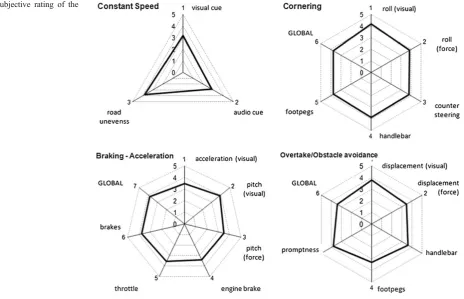
The validation results collected are shown in Fig. 9 by using radar charts for the different evaluation points. It is worth noting that these results are consistent with the judgments that expert riders made during simulator tuning. Moreover, a couple of alternative configurations of the simulator were also tested and the score was lower, as foreseen during tuning.
4 Conclusion
The paper has presented the main features of the motorcycle riding simulator developed by the University of Padova, proposed a method for the objective and subjective evaluation of simulator riding feeling and presented the results of the validation of the DIMEG simulator conducted using a group of 20 riders of different levels of experience. The tests outlined have been done inside the 2BeSafe project in the Seventh European Framework Programme (theme 7—sustainable surface transport), and commenced in January 2009. 2BeSafe is a collaborative research project and its objective is to conduct behavioural and ergonomic research in order to develop countermeasures for enhancing the safety of powered Radius [m] Steady Turning
−10 −17 −25
Aprilia Mana 850
UNIPD SIMULATOR
Aprilia Mana 850
UNIPD SIMULATOR
Aprilia Mana 850
UNIPD SIMULATOR
av_speed 32.74 26.05 36.10 28.57 36.97 33.83
av_Gx −2.29 −0.51 −2.04 0.02 −1.40 0.12
av_Gz −27.42 −35.56 −25.39 −25.92 −22.77 −21.02
av_δ −5.44 −8.93 −4.76 −5.64 −4.36 −3.76
av_τ 13.66 18.13 12.86 8.08 11.25 6.61
acceleration index −1.65 −3.46 −2.17 −2.18 −2.67 −1.87 Table 3 Steady state circular
test indices: comparison between motorcycle and simulator
two wheeler (PTW) riders. This has included research into crash causes and human errors, and the world’s first naturalistic riding study involving instrumented PTWs.
Objective validation demonstrated that the DIMEG mo-torcycle simulator reproduces with good approximation the physics of a real motorcycle. Subjective validation showed that, at the end of a trial and error tuning procedure, the audio visual experience and feelings of movement perceived by the rider had been remarkable increased. In particular, the riding experience has been improved by the installation of the visual
system using three widescreens and the introduction of foot peg control.
Acknowledgment This project has been partially supported by 2BeSafe, grant agreement number 218703.
Open Access This article is distributed under the terms of the Creative Commons Attribution Noncommercial License which per-mits any noncommercial use, distribution, and reproduction in any medium, provided the original author(s) and source are credited.
Appendix 1: Rider feeling questionnaire
Subjective evaluation of simulator riding feeling Participants
No:
Date Time
Simulator Setup
My judgments of the Simulator Riding Feeling are ... (tick one box in every line)
Constant Speed
How is the visual perception of the speed ? good bad Is the noise cue adequate to the speed ? good bad How is the perception of road unevenness (bumps/holes) ? good bad Comments/Suggestions:
Braking/Acceleration
How is the visual perception of speed changing ? good bad How is the visual feel of the motorcycle pitch ? good bad How is the motion/force feel of the motorcycle pitch ? good bad Do you feel the "shift-down" gear braking effect ? good bad Is the acceleration adequate to the throttle effort ? good bad Is the deceleration adequate to the brakes effort ? good bad How is the overall feeling ? good bad Comments/Suggestions:
Cornering
How is the visual perception of the motorcycle roll? good bad How is the motion/force feel of the motorcycle roll ? good bad Is the counter-steering effect realistic ? good bad Is the motorcycle response adequate to the handlebar effort ? good bad Is the motorcycle response adequate to the footpegs effort ? good bad How is the overall feeling ? good bad Comments/Suggestions:
Overtake / Obstacle avoidance
Appendix 2: Validation test protocol
This section describes the test protocol adopted during simulator validation in the 2BeSafe project. Before the test, the experimenter informs the participant on the framework of the project and of the aim of the experiment. In particular, the participant is informed that it is a test of the simulator and not a test of the rider. The test starts with the warm-up phase, followed by the evaluation one. The warm up phase aims to make the participant confident with the simulator commands: handlebar, brakes and clutch. During this phase the experimenter will ask the participant to perform some simple, specific task on a (virtual) free space. The warm up duration is approximately 8–10 min. The evaluation phase duration is approximately 15–20 min of driving in rural and urban environments. Each participant fills in the participant profile questionnaire. During the test the experimenter continuously assists the participant.
Warm up protocol
The experimenter demonstrates to the participant the simulator controls: handlebar and foot pegs, throttle, clutch and front and rear brake.
The participant gets on the simulator and starts riding in a (virtual) open space following the experimenter’s instructions:
& Switch on the engine;
& Accelerate and decelerate using the throttle;
& Pull the clutch lever, enter 1st gear, release the clutch lever in the range between 3,500 and 4,000 rpm; start and maintain a constant speed between 60 and 70 km/h. If necessary and possible, enter 2nd gear using the clutch as explained above;
& On the straight road, push the handlebar with the right hand (i.e. apply a counter-clockwise steering torque): the motorcycle will turn right. Release the handlebar: the motorcycle will come back to the straight motion;
& Still on the straight road, push the handlebar with the left hand (i.e. apply a clockwise steering torque): the motorcycle will turn left. Release the handlebar: the motorcycle will come back to the straight motion;
& Press the right foot peg: the motorcycle will turn right. Depress the foot peg: the motorcycle will come back to a straight motion;
& Load the left foot peg: the motorcycle will turn left. Unload the foot peg: the motorcycle will come back to a straight motion;
& Repeat and combine the tests above until you feel confident with the simulator controls;
& On the straight road, at about 70 km/h, pull the front brake lever slowly; after that, repeat the same test acting
more vigorously on the lever to feel the different behaviour of the pitch during braking;
& Repeat the previous test using the rear brake on the straight road; after this combine the two brake actions;
& On the straight road, accelerate until you enter 6th gear and after that brake using both brakes and the brake engine. Appreciate the varying behaviour in different gears during braking;
& Repeat the previous test on a corner and feel the loss of adherence at the rear in lower gears.
After these initial rules, the test can start for the validation of the simulator following the evaluation protocol.
Evaluation protocol
& The first ride is done in the rural naturalistic scenario i.e. the participant has to ride in a (virtual) rural environment for 8–10 min, with low traffic con-ditions; the experimenter must remember to abide by the traffic rules and not to jeopardise him/herself or the other road users during the ride. Moreover, if the tester has any problems or feels sick during the ride he/she can stop the test immediately.
& The second ride is done in the urban scenario i.e. the participant has to ride in a (virtual) urban environment for 8–10 min, with normal traffic conditions. In addition, in this case the experimenter must remember to abide by the traffic rules and not to jeopardize him/ herself or the other road users during the ride. Moreover, if the tester has any problems or feels sick during the ride he/she can stop the test immediately.
& After these two rides, the participant has to fill in the rider feeling questionnaire.
& The previous 3 steps have to be repeated for each different simulator setup being tested as described above.
References
1. Chiyoda S, Yoshimoto K, Kawasaki D, Murakami Y, Sugimoto T (2000) Development of a motorcycle simulator using parallel manipulator and head mounted display. Driving Simulator Conference, DSC 2000, Paris, France, September 6–7
2. Miyamaru Y, Yamasaky G, Aoky K (2002) Development of motorcycle riding simulator. JSAE Rev 23:121–126
3. Cossalter V, Lot R, Doria A (2003) Sviluppo di un simulatore di guida motociclistico. Proc. of the 16th AIMETA Congress of Theoretical and Applied Mechanics, Ferrara, Italy, September 9–12 2003 4. Ferrazzin D, Barbagli F, Avizzano C, Pietro G, Bergamasco M
(2003) Designing new commercial motorcycles through a highly reconfigurable virtual reality-based simulator. J Adv Robot 17 (4):293–318
American Control Conference, New York City, USA, July 11–13 2007
6. Cossalter V, Lot R, Sartori R, Massaro R. A motorcycle riding simulator for the improvement of the rider safety. FISITA F 2008-11-015
7. Cossalter V, Lot R, Doria A, Maso M (2006) A motorcycle riding simulator for assessing the riding ability and for testing rider assistance systems. 9th Driving Simulation Conference, Paris, France, October 4–6 2006
8. Cossalter V, Doria A, Lot R (2004) Development and validation of a motorcycle riding simulator. FISITA, Barcelona
9. Cossalter V, Lot R (2002) A motorcycle multi-body model for real time simulations based on the natural coordinates approach. Veh Syst Dyn 37(6):423–448
10. Cossalter V, Lot R, Maggio F (2003) A multibody code for motorcycle handling and stability analysis with validation and examples of application. Small Engine Technology Conference & Exhibition, Madison, WI, USA, September 2003, SAE 2003-32-0035/20034335
11. Koch J (1978) Experimentelle und analytische untersuchungen des motorrad-fahrer systems. Dissertation, Berlin
12. Zellner J, Weir D (1978) Development of handling test procedures for motorcycles. Warrendale, PA, SAE 780313
13. Weir DH, Zellner JW (1979) Motorcycle handling - volume I: summary report. U.S. Department of Transportation, 001-05, DOT HS-804 190 MISC
14. Weir DH, Zellner JW, Teper GL (1978) Motorcycle handling -volume II: technical report, U.S. Department of Transportation, No. 1086-1
15. Rice RS (1978) Rider skill influences on motorcycle manoeuvring. Warrendale, PA, SAE 780312
16. Kuroiwa O, Baba M, Nakata N (1995) Study of motorcycle handling characteristics and rider feeling during lane change. Warrendale, PA, SAE 950200
17. Bunz D, Klasen M, Schaffler A (2004) Determination of parameters for objective evaluation of motorcycles driving dynamics behaviour. 5th International Motorcycle Conference, Munich, Germany, Sept 2004
18. Varat M, Husher S, Shuman K, Kerkhoff J (2004) Rider inputs and powered two wheeler response for pre-crash manoeuvres. Proceedings of the 2004 International Motorcycle Safety Conference (Institut Fur Zweiradsicherheit e.v., Munich, Germany)
19. Cossalter V (2002) Motorcycle dynamics. Race Dynamics, Greendale
20. Sharp R (1997) Design for good motorcycle handling qualities. Warrendale, PA, SAE972124
21. Cossalter V, Da Lio M, Lot R, Fabbri L (1999) A general method for the evaluation of vehicle manoeuvrability with special emphasis on motorcycles. Veh Syst Dyn 31(2):113–135 22. Roe GE, Thorpe TE (1980) Improvements to the stability,
handling, and braking of high-performance motorcycles. Motor-cycle Safety Foundation Int. Conference, Washington Proceed-ings, 565–597
23. Schweers TF, Remde D (1993) Objective assessment of motorcycle manoeuvrability. Warrendale, PA, SAE 950200
24. Cossalter V, Lot R, Doria A, Maso M (2006) A motorcycle riding simulator for assessing the riding ability and for testing rider assistance systems. 9th Driving Simulation Conference, Paris, France, October 4-6 2006
25. Sadauckas J, Cossalter V (2006) Elaboration and quantitative assessment of manoeuvrability for motorcycle lane change. Vehicle System Dynamics: International Journal of Vehicle Mechanics and Mobility 44(12):903–920 ISSN 0042-3114 26. Cossalter V, Lot R, Peretto M (2007) Motorcycles steady
turning. Journal of Automobile Engineering 221(Part D):1343– 1356