R E S E A R C H A R T I C L E
Open Access
Master
–
slave manipulator for laparoscopic
surgery using a 6-axis vertical articulated robot
Makoto Jinno
Abstract
Laparoscopic surgery is a minimally invasive surgery that accelerates postoperative recovery, but it can only be performed by surgeons with advanced surgical skills. One of the main difficulties in laparoscopic surgery is restriction of free motion of the forceps because of limited degrees of freedom by the trocar. Recently, many master–slave manipulators with a remote center-of-motion mechanism have been used in laparoscopic surgery to solve this problem.
The master–slave manipulator for laparoscopic surgery using a 6-axis vertical articulated robot has some advantages as a scalable and versatile system. However, to achieve smooth insertion and removal motion of the forceps from the trocar, the problem of restriction of motion by the trocar must be addressed.
This paper describes a master–slave manipulator system for laparoscopic surgery using a 6-axis vertical articulated robot with a slave arm containing forceps. A manipulating mode of the slave arm, consisting of four basic motion modes and three control modes, is proposed in order to perform smooth operations when the motion of the trocar is restricted. The three control modes include a non-trocar mode, a trocar mode, and a transitional mode between the two modes in order to ensure smooth insertion and removal motions of the forceps. Furthermore, the transitional mode consists of a posture adjustment motion and insertion-removal motions. The posture adjustment motion before an insertion motion of the forceps under the transitional mode is achieved by the motions of only the 4th axis and 5th axis of the slave arm. The posture adjustment motion and insertion motion under the transitional mode and the master–slave motion under the trocar mode are shown through evaluations of the master–slave manipulator system, including a 6-axis vertical articulated robot, in order to verify the effectiveness of the proposed methods.
Keywords:Surgical robotics; Minimally invasive surgery; Master–slave manipulator; Vertical articulated robot; Trocar; Forceps
Background
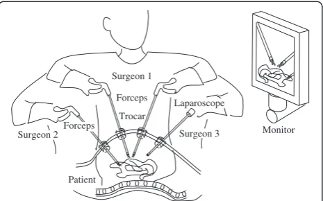
Laparoscopic surgery is one of the most common minimally invasive surgical strategies. As shown in Figure 1 depicting conventional laparoscopic surgery, a surgeon performs pro-cedures using forceps passed through trocars (each approxi-mately 5 to 10 mm in diameter) into a patient’s abdominal cavity while watching an image of the abdominal cavity acquired by a laparoscope. With a small incision, the patient can recover sooner and medical costs are reduced. There-fore, laparoscopic surgery is highly advantageous for the patient and has become widespread in recent years [1].
However, laparoscopic surgery can only be performed by surgeons with advanced surgical skills. One of the main difficulties in laparoscopic surgery is a restriction
of the free motion of the forceps because of lack of degrees of freedom (DOF) by the trocar. The position and posture of the gripper of the forceps cannot be changed freely in the patient’s abdominal cavity during the procedure.
Recently, many master–slave manipulators have been used to solve the difficulties in laparoscopic surgery [2]. The surgeon manipulates the master arm. The slave arm motion is controlled at the same or reduced scale of motion of the master arm. The slave arm has a remote center-of-motion (RCM) mechanism to enable performance of surgi-cal procedures under restricted motion of the trocar [3-5].
Various studies have reported master–slave manipulators for laparoscopic surgery using 6-axis vertical articulated robots or 7-axis redundant vertical articulated robots [6-8]. Furthermore, support mechanisms have been reported for a robotic forceps using a 6-axis articulated robot with active and passive joints [9]. The master–slave manipulator Correspondence:[email protected]
Terumo Corporation, Nakai-machi, Ashigarakami-gun, Kanagawa 259-0151, Japan
for laparoscopic surgery using a 6-axis vertical articulated robot is advantageous as it is a scalable and versatile system. However, to achieve smooth insertion and removal motion of the forceps from the trocar, the problem of the restricted trocar movement must be addressed.
This paper first presents a comparison between 6-axis vertical articulated robots and RCM robots, along with the kinematics of a trocar mode. Second, a manipulating mode of the slave arm consisting of four basic motion modes and three control modes is proposed in order to perform smooth operations under restricted trocar movement. Third, the transitional mode, which is one of three control modes, and a posture adjustment motion before insertion of the forceps under the transi-tional mode are proposed. In addition, the transition state between each control mode is examined. Fourth, an evaluation experimental system, which consists of a slave arm, a master arm, and a controller, is presented. Finally, experimental results are presented to confirm the effectiveness of the basic motion modes, and the methods used in the transition mode between non-trocar and trocar modes are reported.
Methods
Comparison between RCM robots and 6-axis vertical articulated robots
The master–slave manipulator used for laparoscopic surgery in clinical practice has an RCM mechanism to solve the problem of restricted trocar movement. The RCM mechanism has a parallel link mechanism or cir-cular guide mechanism to achieve in/out, up/down, and right/left motions of the forceps in the patient’s abdom-inal cavity. Therefore, the installation position of the base frame of the slave arm is determined based on the trocar position in order to be at the same position as the RCM. The slave arm has 7 DOF; the configuration is 3 DOF of the RCM mechanism for positioning the gripper, 3 DOF on the tip of the slave arm for posture adjustment of the gripper, and 1 DOF for grasping by
the gripper. The slave arm can perform grasping, dissecting, suturing, ligaturing, and cutting tasks from any position and posture inside the patient’s abdominal cavity. The 3 DOF on the tip of the slave arm consist of a roll axis formed by rotation of the forceps shaft, a pitch and yaw axis, and a yaw and roll axis.
In the case of a 6-axis vertical articulated robot for slave arm, the RCM can be controlled by inverse kinematics under conditions of movement restriction by the trocar. The control mode is defined as the trocar mode in this paper.
The entry point into the patient’s abdominal cavity is located at any position in the working area of the slave arm. Therefore, it is possible to insert forceps through the other trocar in a different position without changing the base frame position of the slave arm. The working area of the forceps in the patient’s abdominal cavity depends on the relationship between trocar position and base frame position of the slave arm.
The 6-axis vertical articulated robot has a wide working area outside the patient’s abdominal cavity. Therefore, parts of motions can be automated, such as insertion motion, removal motion, exchange motion to the other forceps, and movement to the home position away from the patient.
Furthermore, the master–slave manipulator using a 6-axis vertical articulated robot is expected to be a versatile system that can be used as a laparoscope-holding robot, conventional forceps-laparoscope-holding robot, robotic forceps-holding robot, assistant surgeon robot, and open surgery robot. Furthermore, the master–slave manipulator is a scalable system, from a single-slave-arm system to a multi-slave-arm system.
Kinematics of trocar mode
Figure 2 shows the joint configuration of the slave arm consisting of a 6-axis vertical articulated robot and an ar-ticulated forceps. When using a 6-axis vertical arar-ticulated robot, the slave arm requires 9 DOF including a gripper in order to move the tip of the forceps to any position and posture within the patient’s abdominal cavity. This is because the DOF are restricted due to the use of a trocar. In the case of motion only inside the patient’s abdominal cavity, 2 DOF of the wrist joint of the 6-axis vertical artic-ulated robot (4th axis and 5th axis) are used as a passive joint. However, every joint must be active to manipulate the forceps in any position and posture outside the patient’s abdominal cavity.
Furthermore, in this paper, 3 conditions are proposed:
(1) The 4th, 5th, and 6th axes intersect at a point. These joints are called manipulator wrist joint coordinate systems. The manipulator wrist joint coordinate systems are the same as those found in conventional industrial robots.
Forceps
Patient
Surgeon 1
Monitor Surgeon 2
Trocar
Surgeon 3 Laparoscope
Forceps
(2) The 6th axis accords with the forceps axis. Rotation of the forceps axis can be performed by rotation of only the 6th axis.
(3) The 7th and 8th axes are located at the distal end of the forceps, and intersect the 6th axis at a point. These joints are called forceps wrist joint
coordinate systems.
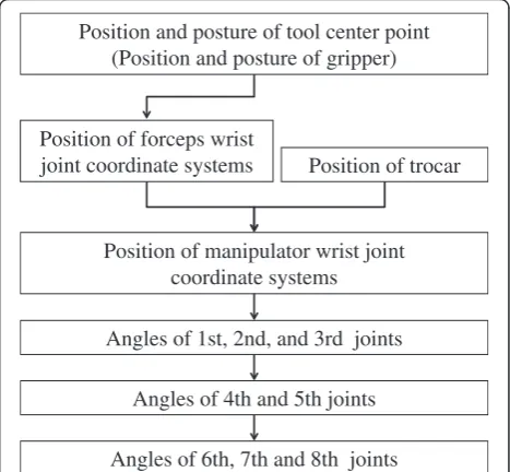
The procedure for calculating inverse kinematics of the trocar mode is described in the following 5 steps, as shown in Figure 3:
(1) The position of the forceps wrist joint coordinate systems is calculated from the position and posture of the tool center point.
(2) The position of the manipulator wrist joint coordinate systems is calculated from the position of the forceps wrist joint coordinate systems and the trocar position.
(3) The joint angles of the 1st, 2nd, and 3rd axes are calculated from the position of the manipulator wrist joint coordinate systems.
(4) The joint angles of the 4th and 5th axes are calculated from the trocar position and the joint angles from the 1st axis to the 3rd axis.
(5) The joint angles of the 6th, 7th, and 8th axes are calculated from the position and posture of the tool center point and the joint angles from the 1st axis to the 5th axis.
In this manner, the solution of each joint angle is obtained.
In the following section, the slave arm is examined with-out the 7th and 8th axes at the tip of the forceps to discuss the basic characteristics of using a 6-axis vertical articu-lated robot for the slave arm. The slave arm without the 7th and 8th axes at the tip is the same configuration as that combined with a laparoscope or conventional forceps instead of articulated forceps.
Basic motion mode
Different types of motion modes are required inside and outside the patient’s abdominal cavity, depending on the
#7 #9
(gripper) #8
Forceps
#2 #3
#1
#5
Base coordinate system
#6 #4
Manipulator
Trocar position Manipulator wrist joint
coordinate systems (#4, #5, #6)
trocar coordinate system
Tool center point (TCP) coordinate system
0
x
0
z
tr
x
tr
z
mw
x
mw
z
fw
x
fw
z
tcp
x
tcp
z
Forceps wrist joint coordinate systems
((#6), #7, #8)
w
x
w
z
World coordinate
system
x
wkwk
z
Work coordinate system
Figure 2Joint configuration of slave manipulator.
Position and posture of tool center point (Position and posture of gripper)
Position of manipulator wrist joint coordinate systems Position of forceps wrist
joint coordinate systems Position of trocar
Angles of 1st, 2nd, and 3rd joints
Angles of 4th and 5th joints
Angles of 6th, 7th and 8th joints
various situations of laparoscopic surgery. Four basic motion modes for manipulation of the slave arm are proposed:
Master–slave motion
The master arm manipulates the slave arm. The mas-ter–slave motion is the most basic motion to manipu-late the forceps inside the patient’s abdominal cavity for an operation. Intuitive hand-eye coordination is obtained by adequate definition of various coordinate systems. For example, coordinate systems might include the world coordinate system, base coordinate system of the slave arm and the master arm, and work coordinate system, depending on the slave arm position and line of sight from the laparoscope.
Jog motion
The tip of the forceps is moved by the user interface, a teaching pendant, or an operating panel at a fixed, pre-scribed speed for each direction of the coordinate axis in the world, base, work, forceps, and joint coordinate systems. The jog motion is used to achieve precise linear motion and positioning that are difficult to obtain with a master–slave motion.
Direct teach motion
In the case of the direct teach motion, the slave arm is moved by the operator’s hands to drive the robot arm joint from the output side without using a human-machine interface such as the master arm or a teaching pendant. The operator can perform manipulations at the patient's bedside while watching the configuration of the slave arm. Direct teach motion is achieved by compensation control of coulomb and viscous friction of each joint and the weight torque of the 2nd and 3rd axes. The desired angles of the 4th and 5th axes under the trocar mode are calcu-lated by the position of the manipulator wrist joint coord-inate systems. The position of the manipulator wrist joint coordinate systems is calculated by the current angles of the 1st, 2nd, and 3rd axes. Therefore, in the trocar mode, the 4th and 5th axes are controlled by conventional position control, whereas the 1st, 2nd, and 3rd axes are controlled by the direct teach motion.
Teaching playback motion
The teaching playback motion is an automatic motion based on the teaching point data and motion programs. The teaching playback motion is used mainly for struc-tured tasks such as the forceps change motion or the
Master-slave
motion Jog motion
Direct teach motion
Teaching playback motion
(1) Non-trocar mode
(2) Transitional mode
Jog motion only direction of forceps axis same as trocar direction
(2)-2 Insert/remove motion
(3) Trocar mode (Remote center of motion)
Master-slave
motion Jog motion
Direct teach motion
Teaching playback motion Point-to-point
motion Jog motion
Direct teach motion
Teaching playback motion
(2)-1 Posture adjustment motion
Motions only of 4th axis and 5th axis
Figure 4Control mode and state transition.
Trocar position Trocar position
Trocar position Trocar position
A
B
C
D
return motion to the home position in order to reduce the surgeon’s workload and improve the efficiency of the operative procedure.
When the forceps is manipulated by the basic motion mode in the patient’s abdominal cavity, the slave arm must be controlled based on the kinematics of the trocar mode.
Main control mode
When the forceps is inserted into or removed from the trocar, easy handling is desired without increasing the
load on the surgeon under any operating conditions. When using a 6-axis vertical articulated robot for the slave arm, the control algorithm must be changed to reflect a state of being inside or outside the patient’s abdominal cavity because the inverse kinematics are different between the non-trocar mode and trocar mode. Therefore, a transition algorithm between the non-trocar mode and non-trocar mode is required.
Prior research using 7-axis vertical articulated ro-bots [8] proposed an impedance controller that is configured with zero stiffness in translations and high stiffness in the rotations. Therefore, the forceps can only move unrestricted in translations. The operator can hold the slave arm with his/her hands and guide it through the trocar [10].
In this study, to achieve smooth insertion and re-moval motion of the forceps from the trocar, 3 types
Master arm
Slave arm
Forceps (dummy)
User interface
Trocar
Controller
Master forceps Virtual
trocar 0
x
z
00
y
Figure 6Configuration of evaluation experimental system.
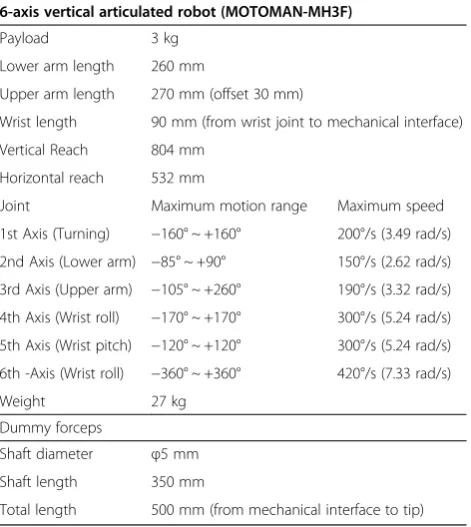
Table 1 Specifications of slave arm system
6-axis vertical articulated robot (MOTOMAN-MH3F)
Payload 3 kg
Lower arm length 260 mm
Upper arm length 270 mm (offset 30 mm)
Wrist length 90 mm (from wrist joint to mechanical interface)
Vertical Reach 804 mm
Horizontal reach 532 mm
Joint Maximum motion range Maximum speed
1st Axis (Turning) −160° ~ +160° 200°/s (3.49 rad/s)
2nd Axis (Lower arm) −85° ~ +90° 150°/s (2.62 rad/s)
3rd Axis (Upper arm) −105° ~ +260° 190°/s (3.32 rad/s)
4th Axis (Wrist roll) −170° ~ +170° 300°/s (5.24 rad/s)
5th Axis (Wrist pitch) −120° ~ +120° 300°/s (5.24 rad/s)
6th -Axis (Wrist roll) −360° ~ +360° 420°/s (7.33 rad/s)
Weight 27 kg
Dummy forceps
Shaft diameter φ5 mm
Shaft length 350 mm
Total length 500 mm (from mechanical interface to tip)
#2
#3
#1 #5
#6 #4 Manipulator
(PHANTOM Omni)
Master forceps
#2(passive) #3(passive)
#1(passive) #4(passive)
Base coordinate system
0
x
0
z
Manipulator wristcoordinate system (#4, #5, #6)
mw
x
mw
z
Operating portion Virtual
trocar
of control modes, including the transition mode, and 4 types of posture adjustment methods are proposed:
Non-trocar mode
The non-trocar mode is a control mode to manipulate the forceps outside the patient’s abdominal cavity. The non-trocar mode uses the conventional inverse kine-matics of the 6-axis vertical articulated robot. The joint angles of the forceps wrist joint coordinate systems are the origin angle of each joint.
Transition mode between non-trocar mode and trocar mode
The transition mode is a control mode to transition from the non-trocar mode to the trocar mode for insertion motion or from the trocar mode to non- trocar mode for the removal motion. The details of the transition mode are described in the next section.
Trocar mode
The trocar mode is a control mode to manipulate the forceps inside the patient’s abdominal cavity. The trocar mode uses the inverse kinematics described in the previ-ous section. Under the non-trocar mode and the trocar mode, it is possible to manipulate the forceps by the 4 types of basic motion modes described in the previous section.
Transition mode between non-trocar mode and trocar mode Furthermore, the transition mode between the non-trocar mode and trocar mode consists of 2 types of motion modes as follows:
Posture adjustment motion
The posture adjustment motion is the motion to adjust the forceps axis to the direction of the trocar from any position and posture outside the patient’s abdominal cavity. The details of the posture adjustment motion are described in the next section. It is necessary to consider the working area of the slave arm and to avoid collision with the trocar or patient.
Insert/remove motion (jog motion only direction of trocar position)
The insert/remove motion is allowed along the forceps axis only when the forceps axis is in a state that it is equal to the direction of the trocar. It is possible to insert the forceps into the trocar or remove the forceps from the trocar by the jog motion.
This control method must be transferred to the trocar mode via the posture adjustment motion and the insert/ remove motion from the non-trocar mode in order to in-sert the forceps into the patient’s abdominal cavity. The control method can be changed to the trocar mode from the transition mode when the insertion length of the for-ceps from the trocar position becomes more than 50 mm.
A
B
C
D
Slave arm
Forceps (dummy)
Trocar
Slave arm
Forceps (dummy)
Trocar
Slave arm
Forceps (dummy)
Trocar
Slave arm
Forceps (dummy)
Trocar
Furthermore, the control method must be transferred to the non-trocar mode via insert/remove motion from the trocar mode in order to remove the forceps from the patient’s abdominal cavity. The control method can be changed to the non-trocar mode from the transition mode when the forceps tip passes through the trocar.
Posture adjustment motion
It is necessary to obtain an entry point, which is the trocar position for the posture adjustment motion in advance by a teaching function or an image recognition function. The teaching method is as follows.
The entry point is provided by a teaching forceps. The tool center point, which is the teaching forceps tip, is led to the entry point on the patient body by the master–slave motion, jog motion, or direct teach motion. Then, the position is stored as the trocar position. This teaching method is the same as a conventional teaching method of an industrial robot. The desired angles of the posture adjustment motion are calculated from the direction of the trocar position from the origin of the manipulator wrist joint coordinate systems, which is calculated from current angles from the 1st axis to the 3rd axis. As a result, the desired angles of the 4th and 5th axes are provided. Therefore, the posture adjustment motion in order to adjust the forceps axis to the direction of the trocar carries out motion in only the 4th and 5th axes. The posture adjustment motion is chosen from the following 4 types of proposed methods in order to enable effective posture adjustment motion under any operation conditions.
Posture adjustment by point-to-point motion using only the 4th and 5th axes
The slave arm moves to the desired angles of the 4th and 5th axes by synchronous motion.
Posture adjustment by jog motion using the 4th and 5th axes The slave arm is moved by jog motion in only one direction to the desired angles of the 4th and 5th axes.
Posture adjustment by direct teach motion using the 4th and 5th axes
The slave arm is moved by the direct teach motion in only one direction to the desired angles of the 4th and 5th axes.
Posture adjustment by teaching playback motion
Posture adjustment by the teaching playback motion is an automatic motion based on the teaching point data file and the motion program file that are made in advance. The forceps axis of the teaching point must be in accord-ance with the trocar direction. In the case of posture
adjustment by teaching playback motion, all joints of the slave arm are moved.
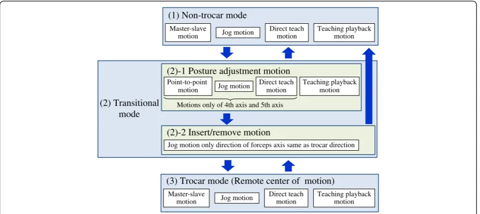
The basic control mode and state transition are shown in Figure 4. The insert motion flow from the non-trocar mode to the trocar mode is shown in Figure 5.
Configuration of evaluation experimental system
An evaluation experimental system with a 6-axis verti-cal articulated industrial robot was constructed in order to evaluate the basic motion modes of the kinematics of the trocar mode and the transition algorithm be-tween non-trocar and trocar modes. The evaluation experimental system consisted of a slave arm, a master arm, and a controller as shown in Figure 6.
The 6-axis vertical articulated industrial robot of the slave arm was made by YASKAWA Electric Corporation (MOTOMAN-MH3F) for industrial use. The specification of the slave arm is shown in Table 1. In order to evaluate the positioning of the tip of the forceps without a posture, a dummy forceps with a cylindrical stick shape 5 mm in diameter was used.
The master arm was a three-dimensional pointing device made by SensAble Technologies, Inc. (PHANTOM Omni). Two types of operating methods of the master
-150 -100 -50 0 50
y
0
[mm]
Trocar mode (Master -slave motion) Insert motion
Posture adjustment motion
Trocar position
50 100 150 200 250 300 350 400
400 450 500 550 600 650
z
0
[mm]
x
0[mm] Point-to-pointmotion
Jog motion
Direct teach motion
Posture adjustment motion
Trocar mode (Master -slave motion) Insert
motion
Trocar position
arm were prepared. One was conventional direct oper-ation of the master arm with a pen-shape device. The other was a master forceps operation of the master arm with a dummy forceps and a virtual trocar. The master arm with the dummy forceps is shown in Figure 6. The master arm with the dummy forceps and the virtual trocar can demonstrate good operating conditions for laparo-scopic surgery by maintaining a comfortable position and posture for the surgeon.
Figure 7 shows the joint configuration of the master arm with the dummy forceps and the virtual trocar. The desired point of the slave arm was acquired by the relative position of the origin of the wrist joint coordinate systems of the PHANTOM Omni. A foot switch changed the on-off control of the master–slave mode.
The control system of the slave arm was developed and executed in real time on the RTLinux operating system.
-150 -100 -50 0 50 100
y
0
[mm] Trocar mode
(Master -slave motion) Trocar position
Posture adjustment motion
Insert motion
50 100 150 200 250 300 350 400
400 450 500 550 600 650
z
0
[mm]
x
0[mm]Initial point 1 Initial point 2 Initial point 3
Posture adjustment motion
Trocar mode (Master -slave motion) Insert
motion
Trocar position
Figure 10Forceps tip trajectories of insert motions (Comparison of initial positions of forceps tip).
40 40
30 30
20 20
10 10
0
]
0
-10
w
k
[
10
y
w
20 -20
-3030
40 -40
-40 -30 -20 -10 0 10 20 30 40
Forceps tip
Forceps tip trajectory target
Trace
[mm]
x
wk[mm
Start point
End point
Figure 11Trace target and forceps tip trajectories by master forceps.
Trocar position (x0,y0,z0)
=(500,0,200)
Dummy forceps
Laparoscope
Trace target
Trocar
xwk
zwk
ywk
x0
z0
y0
Figure 12Configuration of trace task.
0 0.2 0.4 0.6 0.8 1
0 10 20 30 40 50 60 70
distance [mm]
time [s]
Results and discussion
The insert motion, remove motion, and master–slave motion were performed by the evaluation experimental system.
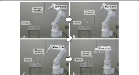
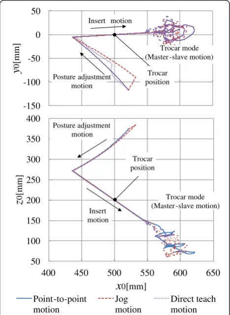
Figure 8 shows the overview of the insert motion from the non-trocar mode to trocar mode via the transitional mode. Figures 9 and 10 show the trajectories of the dummy forceps tip for the insert motions from the posture adjustment, insert, and master–slave motions. These figures show the dummy forceps tip trajectories calculated by the forward kinematics from the joint angles based on the base coordinate system in the XY and XZ planes. The trocar position on the base coordinate system is (x0, y0, z0) = (500, 0, 200).
Figure 9 shows 3 types of posture adjustment motions by point-to-point, jog, and direct teach motions using the 4th and 5th axes from the same start positions. After the posture adjustment motions, the dummy forceps began the insert motion from same point and passed through the trocar. Furthermore, after the insert motion, the master–slave motions were achieved by the master arm with the dummy forceps and the virtual trocar.
Figure 10 shows the posture adjustment motions by point-to-point motion using the 4th and 5th axes be-ginning from 3 different positions. After the posture adjustment motions from 3 different starting positions, the dummy forceps began the insert motion and passed through the trocar, and the master–slave motions were achieved by the master arm.
Figure 11 shows the dummy forceps tip trajectories of the slave manipulator when the operator traces the target by the master arm, as shown in Figure 12. Figure 13 shows the calculated distance from the joint angles between the trocar point and forceps axis under the trace task by the master slave motion. The maximal error, which is the maximal distance, was less than 1 mm.
The evaluation experimental system confirmed that the operator can carry out the master–slave motion under the trocar mode through the transition mode that consists of the posture adjustment and insert/remove motions.
Conclusions
To enable smooth operations when the motion of the trocar is restricted because of the use of a 6-axis verti-cal articulated robot for the slave arm, a manipulating mode of the slave arm consisting of 4 basic motion modes and 3 control modes has been proposed. Especially, the posture adjustment motion, which is the motion to adjust the forceps axis to the direction of the trocar from any position and posture outside the patient’s abdominal cav-ity, is achieved by movement only in the 4th and 5th axes of the slave arm. The state transition between each control mode has also been demonstrated. Furthermore, the
posture adjustment motion and the insert motion under the transitional mode and the master–slave motion under the trocar mode have been verified by evaluation experi-ments of the master–slave manipulator system including a 6-axis vertical articulated robot in order to confirm the ef-fectiveness of the proposed methods.
Future work for clinical use will include hardware and software development, such as construction of an articulated forceps, systematization of a multi-slave-arm system, planning of a working space, developing a control method in the vicinity of the singular point, and verifying the operability and safety of the system.
Abbreviations
RCM:Remote center of motion; DOF: Degrees of freedom.
Competing interests
The author declares that he has no competing interests.
Received: 4 October 2014 Accepted: 26 November 2014
References
1. Japan Society for Endoscopic Surgery (2012) 11th Nationwide survey of endoscopic surgery in Japan. J Jpn Soc Endosc Surg 17(5):572–694 (in Japanese)
2. Intuitive Surgical, Inc the da Vinci® Surgical System. http://www. intuitivesurgical.com/, accessed 9 Sep 2014
3. Guthart GS, Salisbury JK (2000) The intuitive telesurgery system: overview and application. In: Proc. IEEE international conference on robotics and automation, pp 618–621
4. Mitsuishi M, Arata J, Tanaka K, Miyamoto M, Yoshidome T, Iwata S, Hashizume M, Warisawa S (2003) Development of a remote minimally-invasive surgical system with operational environment transmission capability. In: Proc. IEEE international conference on robotics and automation., pp 2663–2670 5. Tadano K, Kawashima K, Kojima K, Tanaka N (2010) Development of a
pneumatic surgical manipulator IBIS IV. J of Robotics and Mechatronics 22(2):179–188
6. Matusmoto Y, Katsura S, Ohnishi K (2003) Bilateral control with the virtual supporting point for minimally invasive surgery. In: Proc. Technical Meeting on Industrial Instrumentation and Control, the Institute of Electrical Engineers of Japan IIC-03-33. pp 93–97 (in Japanese)
7. Mayer H, Nagy I, Knoll A, Schirmbeck EU, Bauernschmitt R (2004) The Endo [PA]R system for minimally invasive robotic surgery. In: Proc. IEEE international conference on robotics and automation., pp 3637–3642 8. Tobergte A, Konietschke R, Hirzinger G (2009) Planning and control of a
teleoperation system for research in minimally invasive robotic surgery. In: Proc. IEEE international conference on robotics and automation., pp 2098–2105 9. Jinno M, Sunaoshi T, Miyagawa T, Hato T, Matsuhira N, Morikawa Y, Ozawa
S, Kitajima M (2006) Development of robotic forceps for laparoscopic surgery. J of Robotics and Mechatronics 18(3):249–254
10. Konietschke R, Hagn U, Nickl M, Jorg S, Tobergte A, Passig G, Seibold U, Le-Tien L, Kubler B, Groger M, Frohlich F, Rink C, Albu-Schaffer A, Grebenstein M, Ortmaier T, Hirzinger G (2009) The DLR MiroSurge–A robotic system for surgery. In: Proc. IEEE international conference on robotics and automation, pp 1147–1148
doi:10.1186/s40648-014-0023-6