R E S E A R C H
Open Access
Image steganography based on color
palette transformation in color space
Eugenijus Margalikas
1and Simona Ramanauskait
ė
2*Abstract
In this paper, we present a novel image steganography method which is based on color palette transformation in color space. Most of the existing image steganography methods modify separate image pixels, and random noise appears in the image. By proposing a method, which changes the color palette of the image (all pixels of the same color will be changed to the same color), we achieve a higher user perception. Presented comparison of
stegoimage quality metrics with other image steganography methods proved the new method is one of the best according to Structural Similarity Index (SSIM) and Peak Signal Noise Ratio (PSNR) values. The capability is average among other methods, but our method has a bigger capacity among methods with better SSIM and PSNR values. The color and pixel capability can be increased by using standard or adaptive color palette images with smoothing, but it will increase the embedding identification possibility.
Keywords:Color space, Stegoimage, Steganography, RGB
1 Introduction
Nowadays, the phrase “Who owns the information, he owns the world” has a little bit different meaning, com-pared to the initial formulation. In 1815, information on Napoleon’s defeat resulted in the Rothschilds in 1 day to earn 40 million pounds and became the owners of a large part of the British economy. Nowadays, informa-tion can lead to the defeat of informainforma-tion systems, orga-nizations, and countries as well. Therefore, the data confidentiality is important as never before.
Cryptography is used in most cases to ensure data confidentiality. However, encrypted data is not resistant to encryption identification. By encrypting only import-ant, secret data, we can highlight it in the overall data flow and advanced search methods are capable to iden-tify encrypted data. This leads to an increase in data camouflage technologies.
Steganography is the science of hiding data. While digital steganography hides data into digital files and ob-jects, image steganography is designed to hide the data into digital images and raster graphics. This type of steg-anography is one of the most popular as hardly anybody would think to look for secret information in image files.
Image imperceptibility is the main feature to identify steganography method usage, and it is at odds with steg-anography capacity. The balance of these two character-istics is very important to assure the steganography method quality.
This work aims to increase the imperceptibility of image steganography by changing the color palette ra-ther than the color of separate pixels. The work involves the design of a new steganography method, suitable to hide data and to read it after the embedding into the cover images as well as ensure enough data can be em-bedded into the color image.
Our contributions are as follows:
We proposed a novel color palette transformation steganography method which is based on image color palette presentation and division into RGB cubes with one color only. This allows color change within the area of the RGB sub-cube and provided the possibility to embed stegomessage and ensure color similarity.
Our approach has perception configuration possibility to ensure the acceptable modification level.
© The Author(s). 2019Open AccessThis article is distributed under the terms of the Creative Commons Attribution 4.0 International License (http://creativecommons.org/licenses/by/4.0/), which permits unrestricted use, distribution, and reproduction in any medium, provided you give appropriate credit to the original author(s) and the source, provide a link to the Creative Commons license, and indicate if changes were made.
* Correspondence:simona.ramanauskaite@vgtu.lt
2Vilnius Gediminas Technical University, Vilnius, Lithuania
In comparison to other steganography methods, our proposed method has a balance between user perception and embedding capability.
To achieve the aim, a systematic literature review was executed to find existing steganography methods, their imperceptibility, and capability measurements. Based on existing solutions, we generated a new steganography method. This method uses color palette transformation, based on color location modification in divided RGB cube with one color only. The proposed method was val-idated by using the most commonly used images (Ba-boon, Barbara, Lena). Peak Signal Noise Ratio (PSNR) and Structural Similarity Index (SSIM) steganography measurements as well as capability calculations were cal-culated. This was the base for comparative analysis. An additional experiment was executed to identify the pro-posed steganography properties by using BSD-300 and Kodak datasets. Additionally, 108 randomly selected, dif-ferent type images from the personal gallery were used to analyze the proposed method application. All experi-ments are summarized, and final conclusions are derived at the end of the paper.
2 Related works
To secure data, cryptography algorithms are used. Cryptography allows data confidentiality assurance by encrypting data with a secret key. Encrypted data is not hard to be noticed. To provide the message secrecy, it can be sent over hidden channels or embedded into other objects to camouflage its existence. For this pur-pose, steganography is the best solution. It embeds a message into another object. Therefore, it is hard to identify where and how the message was hidden.
Another steganography usage possibility is object watermarking. By embedding the owner’s data into the image or another object, everybody can decode it and find the owner’s data. At the same time, steganography usage for image watermarking is very limited, as no modifications are allowed after the message embedding. If the image is modified, the embedded data will be changed and we will not be able to retrieve the informa-tion. This applies to all steganography algorithms, despite the used method or application area. More ad-vanced watermarking and tempering recovery methods exist [1–3] for image signing purpose.
There is a variety of steganography methods, and they can be classified according to different properties. One of the properties, which can be used to classify steganog-raphy, is the need for shared data (except the methods and its parameters). For example, Chen et al. [4] propose a steganography method where the sender and the re-ceiver own the cover image. By using this method, the receiver uses the cover image to get the embedded data
from the stegoimage. The need for the original, cover image is not flexible in term of steganography usage. The biggest part of steganography methods does not re-quire shared data. The least significant bit (LSB) stega-nography method embeds the secret message in the least significant bits of pixel values of the cover image [5]. Each pixel of the cover image is divided into RGB parts, and the least significant bits are replaced with the mes-sage bits. The change in color usually is far lesser than that perceivable by average human vision. The receiver needs to know the used steganography method and how many bits were used for the stegomessage, so there is no need for shared data for this method.
The LSB steganography can be assigned to spatial domain category. This classification is based on image enhancement domain techniques and has two main categories [6]:
1) Spatial domain—directly deals with the image pixels [7]. The manipulation with pixels leads to the fact it has high embedding capacity, has shorter
computational time, and is vulnerable to geometric attacks.
2) Transformation domain—deals with the image frequency content [8]. The need for transformations influences the higher computational time and limited embedding capacity, but it is more robust against geometric attacks and compression.
LSB steganography is the most well-known spatial do-main algorithm. Another example of spatial dodo-main image steganography is pixel value differencing (PVD) [9]. This method is more imperceptible compared to LSB as the stegomessage is embedded by taking into ac-count the difference between the colors of the pixel pair. The method does not embed a stegomessage where it might cause too big changes in the cover image. This re-duces the capacity as not all pixels can be changed by embedding stegomessage. Another approach is based on pixel value ordering (PVO) when a digital image is sliced into blocks and each block is arranged according to the pixel value [10]. Usually, the differences between the two largest and two smallest values are analyzed while only the maximum and minimum values are changed to achieve the best results. Modifications of this method exist [11], where middle value is used too and leads to the increase of stegomessage length.
Transformation domain steganography methods, first of all, execute some transformations. There are some ex-amples of steganography methods, where different trans-formations are used:
Senthooran and Ranathunga [13] apply DCT coefficients and modified quantization table values.
Mazumder and Hemachandran [14] use DWT and change the stegomessage by optimizing message dispersion.
Patel and Ragha [15] adopt binary image steganography and IWT.
Dalvi and Kamathe [16] apply DWT and SWT.
Huang and Zhou [17] extend the HUGO algorithm [18] by using a hybrid quantitative MINMAX feature.
The idea of transformation domain steganography methods is to identify the edges between multiple re-gions [19] in the image where color changes would be less visible or to change the color for the plain re-gion at once [20]. Image context understanding and captioning gaining enough accuracy just now [21] and the steganography does not take advantage of embed-ding messages to the background, unrecognized ob-jects yet. The possibility to embed a message in text areas [22] is a consideration for the future steganog-raphy too. All techniques dedicated to identifying ob-jects, edges, and the text are or can be used to optimize the user imperceptibility, when the user is not able to notice some color changes in the image.
While most steganography methods rely on chan-ging values of separate pixels, there are methods where the color palette is transformed. Color palette-based steganography is used by Seppanen et al. (SMK) [23]. These authors used a small color palette to conceal information within a color image. Brisbane et al. [24] proposed a pixel selection method and spherical coding structure method using shared color palette (SCP). The idea to change the color palette is used by Michiharu et al. [25] where image color space is decomposed into RBG components and chan-ged to fit into the maximum number of colors after embedding data according to BPCS [26] algorithm. Raja et al. [27] also decompose the image color pal-ette, cluster it, and provide indexes of shifted cen-troids. We believe there is space for another steganography method which uses color palette trans-formation. Therefore, we propose a method for color palette transformation in color space.
3 Proposed method for color palette transformation in color space
3.1 Requirements for the steganography method
To increase the perception, we use color palette transformation rather than changing separate image pixels. As all pixels of the same color will be changed into one different color, areas of constant color will not be distorted. Illustration of color palette
transformation advantages against separate pixel color changes is presented in Fig. 1. Figure 1a shows how changed pixels disturb the pattern of the original image (Fig. 1b), while the pattern remains the same in color palette transformation as shown in Fig. 1c.
To hide the message and later read the embedded message in a transformed image, we define some re-quirements for the color palette-based steganography algorithm:
1) Each color from the original image has to be changed into a unique color as if multiple colors will be changed into the same color, later we will not be able to identify changes.
2) The distance between similar colors has to be taken into account:
a) The color change should“stay”in the same “color range”to make sure the image will contain the same pixel pattern.
b) The number of the embedded bit should be selected according to the distance between similar colors as the user will be less perceptive to bigger color changes between two different colors compared to the same change in different shades of the same color.
3) No reference models need to be used, but there should be a possibility to adjust the algorithms for a different level of color palette changes.
Most of the presented requirements are the base for most steganography methods (for example LSB satisfies the second and third requirement, while the first re-quirement is different as changes pixel color, rather than color).
When all colors are stored in the RGB cube, we calcu-late where stegomessage bit can be stored the cube:
1) If the RGB cube of sub-cube has more than one color in it, the cube has to be divided into sub-cubes. Each edge of the cube is divided into two parts, so we have eight sub-cubes and each color of the cube will belong to one of the sub-cubes. All eight sub-cubes will be processed recursively as the initial RGB cube till the sub-cube will have one or zero colors in it.
2) If the RGB cube or sub-cube has one color, we analyze the size of the cube:
a) If the sub-cube size is 1 × 1 × 1, it means there is only one possible color location in it and we cannot change it into another color within the range of the sub-cube. This cube is not suitable for stegomessage embedding.
b) If the size of the RGB sub-cube is more than 1 × 1 × 1, it means we can change the location of the color. We use this cube or part of this cube to embed the stegomessage. The change is lim-ited to be in the area of this RGB sub-cube only. This ensures that we will be able to decompose the changed RGB cube in the same sub-cubes after the embedding of stegomessage as well as the new color will not overlap with other colors in the RGB cube.
3) If the RGB sub-cube has no colors, it will not be processed anymore as it means there are no colors that have to be changed (the area of the RGB cube is not used in the image). We are not using these cubes to embed stegomessage.
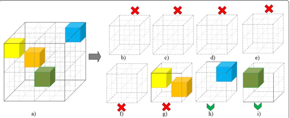
The dividing fragment of the selected RGB cube into sub-cubes is presented in Fig. 2. The figure illustrates Fig. 1Original image (b), image with changed separate pixels (a), and image with changed color palette (c)
the processing of one cube to eight smaller sub-cubes. Eight divided sub-cubes are further analyzed re-cursively. Only sub-cubes with at least one color in it and with cube edge length greater than 2 are analyzed for division further.“Empty” or too small sub-cubes are not divided anymore.
When RGB cube of size more than 1 × 1 × 1 and with one color in it is found, we can embed the stegomessage in it by changing the location of the color in the cube. How many bits Nof stegomessage can be embedded in this cube depends on the length of the edge n of the cube or the number of possible color locations kin the cube (1).
N¼3∙log2n¼ log2k ð1Þ
Based on the example in Fig. 2, we will have only two sub-cubes where the message can be embedded (sub-cubes “h” and“i”). The length of the edge n of each of those sub-cubes is 2; therefore, we will be able to embed 6 bits (3·1 + 3·1).
Nbits of stegomessage are treated as a new location of the color in the RGB cube. We delete the existing color in the cube and replace it with a new color in the cube. As the color location stays in the same cube, we will be able to decompose the color space into the sub-cubes. The stegomessage will be read from RGB cubes of size more than 1 × 1 × 1 where only one color exists. This means we will be able to find the same RGB cubes, where stegomessage bits were stored and compose the stegomessage back with no complications.
The stegomessage is expressed in binary code, and 3log2(n) bits are selected to be used as coordinates
of the specific RGB sub-cube—log2(n) bits define the
position in R-axis, log2(n) bits for G-axis, and log2(n)
bits for B-axis.
For example, we want to embed a message 111010 into the cube, presented in Fig.2. Each sub-cube will use three bits of the stegomessage. Each axis will be pre-sented by one bit as one bit has two possible values as well as the sub-cube axis has two possible values. The center of coordination system, coordinates (0, 0, 0) are in the bottom left corner, closest to us. Therefore the new location for sub-cube “h” in Fig. 2 will be in the same place, coordinates (1, 1, 1) in the sub-cube. The color of sub-cube “i” will be changed to coordinates (0, 1, 0) in the sub-cube. This will change the color, but the color will be in the range of the sub-cube and the color change will not be very contrast to the existing one. All the rest sub-cubes are not suitable for message embed-ding, but all sub-cubes will be combined into the initial RGB cube (see Fig.3).
Each axis in RGB cube has 256 values in 24-bit depth image, and by dividing the cube into the sub-cubes, the length of sub-cube length can be 256, 128, 64, 32, 16, 8, 4, or 2. According to the distribution of image colors in the color space, the size of RGB cubes with bits of stegomessage can vary a lot. To define the desired perception level of the stegoimage, the method applies an additional condition—if the size of RGB cube with one color is too big, we can treat it as a block with more than one color in it and divide it into sub-cubes. After dividing such a cube, only one sub-cube will have one color in it while the rest will have no colors in it. This will reduce the number of possible stegomessage bits N to be written and at the same time will impact smaller color palette changes.
Fig. 3Changed RGB cube (a), which was composed of all sub-cubes. Only sub-cubeshandiwere suitable for embedding, while sub-cubes from
When all suitable RGB cubes were changed by embed-ding the stegomessage bits in it, we change the cover image by replacing the old color values with the new ones. As we are changing the color palette, all pixels of the same color will be changed to a new color. However, no compression or other transformations can be done after the color change and the image has to be stored as a new image (or a new version of the same image).
For message decoding, the same actions should be executed to get sub-cubes with one color in it. As the algorithm is the same and message embedding changed the color, but left it in the same sub-cube, the list of sub-cubes will be identical as in the en-coding algorithm. Therefore, only coordinates of the color have to be gathered and composed into one se-quence to decode the embedded message. As an ex-ample in Fig. 3, we will get eight sub-cubes, but only sub-cubes “h” and “i” will be suitable for message reading (have only one color in it). By keeping the same sequence, we get the coordinates of the colors in those sub-cubes: (1, 1, 1) and (0, 1, 0). By convert-ing each value into binary code and combinconvert-ing into
one sequence of bits, we get the embedded message 111010.
To identify the end of the stegomessage, it should end with some specific symbols (bit sequence). This will ensure the end of the stegomessage will be iden-tified during the decoding and there will be no re-dundant information at the end of the message. A short bit sequence like two bytes of zeros will not be very noticeable for steganalysis as the bits might be embedded in different size and location sub-cubes. Therefore, it will not help to identify the method usage or message embedding fact.
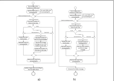
The algorithm of message embedding is presented in Fig.4a and retrieving in Fig.4b.
The palette changing might seem not enough for stego-message storing. However, in an ideal situation, where image colors are distributed in the RGB cube to form all 2 × 2 × 2 cubes to have one color in it, the stegomessage length for 24-bit depth image can be 768 KB. This method does not depend on the size of the image directly (de-pends on the number of colors in the image) too and can excellence for lower resolution images with many colors.
4 Results of proposed steganography method evaluation and discussion
To prove the suitability of the proposed steganography method, its comparison to other steganography methods was executed and experiments on method application with different cover images were added.
4.1 Comparison of stegoimage quality metrics
The most used image quality metrics in steganography are Peak Signal Noise Ratio (PSNR) and Structural Simi-larity Index (SSIM) [26]. The PSNR (dB) is used to measure the visual quality of the stegoimage and evalu-ates the image quality between the input imagefand the stegoimageg. For the image of sizeW×H, the PSNR be-tweenfandgis defined by:
PSNRðf;gÞ ¼10 log10 255 2
1
MN
XM
i¼1
XN
j¼1 fij−gij
2
0 B @
1 C A
ð2Þ
The SSIM is another image quality metric used to measure the similarity between images f and g and is considered to be correlated with the quality perception of the human visual system (HVS). The calculation of SSIM value includes three correlation loss factors l, s, andc:
SSIMðf;gÞ ¼l fð ;gÞc fð ;gÞs fð ;gÞ ð3Þ
l fð ;gÞ ¼μ22μfμgþC1
f þμ2g þC1 ð 4Þ
c fð ;gÞ ¼ 2σfσgþC2
σ2
f þσ2g þC2 ð 5Þ
s fð ;gÞ ¼ σfgþC3
σfσgþC3 ð
6Þ
The l(f, g) (4) is the luminance comparison function which measures the closeness of the two images’ mean luminance (μf and μg). The c(f, g) (5) is the contrast
comparison function which measures the closeness of the contrast of the two images by using the standard de-viationσfand σg. The s(f,g) (6) is the structure compari-son function which measures the correlation coefficient between the two imagesfandg. Theσfgis the covariance between f and g. The positive constants C1, C2, and C3 are used to avoid a null denominator [28].
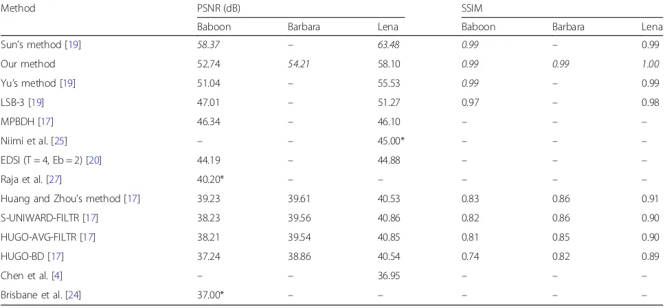
We use well-known images (Baboon, Barbara, and Lena) of size 512 × 512 to compare the results of our method with the results of other existing steganography methods. We used three messages (zeros, ones, and ran-domly generated) and calculated the average of PSNR and SSIM values as well as capacity (number of bits, which can be embedded in the image). All the data is presented in Tables1and2.
Data for other methods were obtained from an ana-lysis of other authors; therefore, some methods are not tested with the images and SSIM or capacity values are not provided. This complicated the comparison, and we were not able to implement the steganography methods.
Table 1Quality comparison results of different steganography methods
Method PSNR (dB) SSIM
Baboon Barbara Lena Baboon Barbara Lena
Sun’s method [19] 58.37 – 63.48 0.99 – 0.99
Our method 52.74 54.21 58.10 0.99 0.99 1.00
Yu’s method [19] 51.04 – 55.53 0.99 – 0.99
LSB-3 [19] 47.01 – 51.27 0.97 – 0.98
MPBDH [17] 46.34 – 46.10 – – –
Niimi et al. [25] – – 45.00* – – –
EDSI (T = 4, Eb = 2) [20] 44.19 – 44.88 – – –
Raja et al. [27] 40.20* – – – – –
Huang and Zhou’s method [17] 39.23 39.61 40.53 0.83 0.86 0.91
S-UNIWARD-FILTR [17] 38.23 39.56 40.86 0.82 0.86 0.90
HUGO-AVG-FILTR [17] 38.21 39.54 40.85 0.81 0.85 0.90
HUGO-BD [17] 37.24 38.86 40.54 0.74 0.82 0.89
Chen et al. [4] – – 36.95 – – –
Brisbane et al. [24] 37.00* – – – – –
The results in Table1show our method is in the lead group in terms of SSIM value—none of the methods was able to get better value for all tested images. Sun’s pro-posed method [19] leads according to the PSNR value, but our method goes just after it and shows similar re-sults as Yu’s method [19].
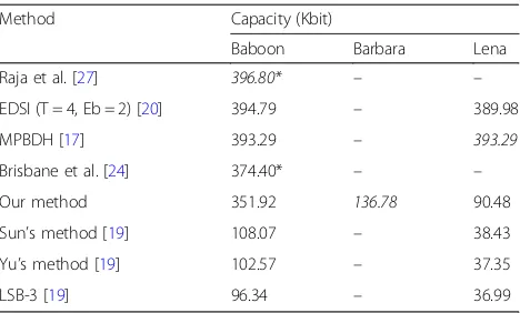
Despite the fact that there are other methods with bet-ter PSNR and SSIM values, results of our method are close to the leaders while the capacity of our method is up to three times bigger compared to Sun and Yu’s methods (see Table 2). Our method is not a leader ac-cording to the capacity in the overall ranking. The method of Raja et al. claims to be the leader, but cap-acity cannot be accurately compared, as it achieved 6.2 bits per pixel capacity, but with 256 × 256 px image ra-ther than 512 × 512 px. The fourth result is achieved with the 256 × 256 image too. The Brisbane et al. pro-posed method is possible to embed at up to 6 bits per pixel with a PSNR of 40 dB but up to 24 Kbit shared data is needed for it. The second and third results (EDSI and MPBDH methods) show similar results. Our pro-posed method does not fall very far from those four methods as the sixth results are three times smaller compared to ours.
We were not able to find data on some steganography method capabilities for the analyzed images, but we be-lieve our method can balance between the capacity and image quality and user perception.
4.2 The experiment of the proposed method application on computer vision image datasets
To analyze the message embedding possibilities of our proposed steganography method, two image datasets were selected—BSD-300 and Kodak Lossless True Color Image Suite.
BSD-300 image dataset [29] is dedicated to image seg-mentation and boundary detection. This dataset includes 300 images (100 for testing and 200 for training). We do
not use the segmentation and boundary detection data, just images. All images in the dataset are in JPG file for-mat and 481 × 321 px dimensions. After embedding ran-domly generated stegomessages into all BSD-300 images, we calculated how many colors the image has, how many sub-cubes can be used for message embedding, how many bits can be embedded into the image, and what are the PSNR, SNR, and SSIM values after embed-ding randomly generated stegomessage into the cover image. The experiment data is presented in Table3. The results of this experiment show the message embedding capacity for BSD-300 dataset is 0.45 bits for one pixel or 1.86 bits for one color. While the embedding capacity varies a lot for different images, the PSNR and SSIM values are stable.
As BSD-300 image dataset contains JPG files only, we used Kodak Lossless True Color Image Suite [30] too to get images of PNG format. Kodak image dataset was se-lected as it is the base of TID2013 image dataset [31], but the images have bigger dimensions. We used this dataset and generated additional variants of the im-ages—all combinations of JPG and PNG file formats of 512 × 768, 341 × 512, 227 × 341, 151 × 227, 101 × 151, and 67 × 101 size were generated. This allowed having 288 cover images instead of the original 24 Kodak im-ages. The purpose of having different size versions of the images was the desire to experiment how the number of colors depends on the embedding capacity and perception while similar color distribution should be kept by using the same content of the images. By re-ducing the size of the image, the number of colors is decreasing as well, while the color distribution should remain very similar.
For extended Kodak Lossless True Color Image Suite, the average message embedding capacity is 55,803 bits and varies a lot (standard deviation is 43,727). The smal-lest capacity is for image kodim02.png of size 68 × 101 px. But this image has the smallest number of colors in the image too—3350 colors. The method was able to embed 0.83 bits/px or 1.67 bits/color for image kodim02.png of size 68 × 101 px.
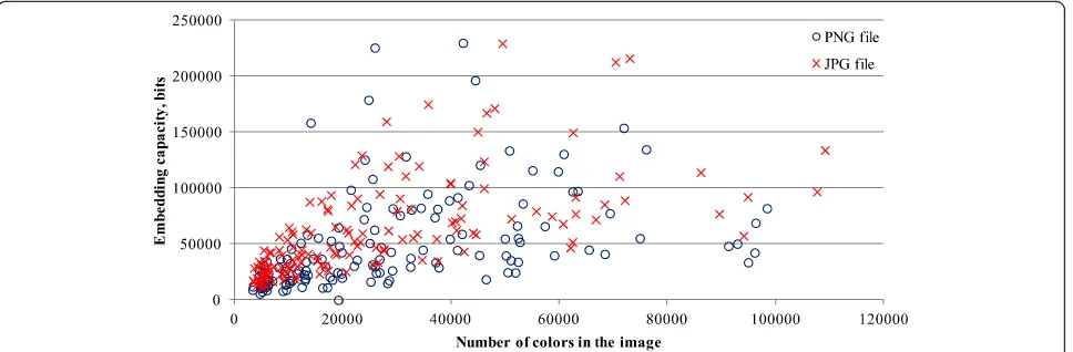
The smallest message embedding capacity per pixel is for image kodim16.jpg of size 512 × 768 px—0.09 bits/ px. Image kodim16.png of size 341 × 512 has the smal-lest message embedding capacity per color—0.45 bits/ color. The biggest relative capacities reach 6.58 bits/px and 7.16 bits/color. We were not able to inspect a strong correlation between image and stegomessage embedding capabilities (correlation coefficient is less than 0.1). The bigger message embedding capability can be noticed in images with more different colors (see Fig.5).
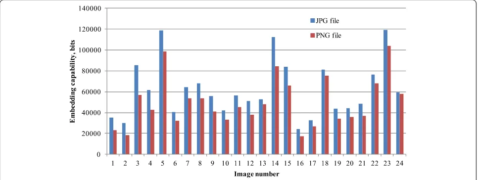
The importance of color palette can be noticed in Fig. 6, where embedding capacity dependency on several colors in the image is presented (see Fig. 6).
Table 2Embedding capacity comparison results of different steganography methods
Method Capacity (Kbit)
Baboon Barbara Lena
Raja et al. [27] 396.80* – –
EDSI (T = 4, Eb = 2) [20] 394.79 – 389.98
MPBDH [17] 393.29 – 393.29
Brisbane et al. [24] 374.40* – –
Our method 351.92 136.78 90.48
Sun’s method [19] 108.07 – 38.43
Yu’s method [19] 102.57 – 37.35
LSB-3 [19] 96.34 – 36.99
Linear dependency can be noted, but the value distribu-tion is very high. It shows the importance of the color palette distribution in the image, not just the number of colors in the image.
Analysis on how the file format influences the embed-ding capability revealed some tendencies (correlation be-tween file format and embedded bits per pixel is 0.184, correlation between file format and bits per color is 0.347)—in JPG file format images, 25% bigger stegomes-sage can be embedded (average embedded stegomesstegomes-sage size for PNG files is 49,632 bits and for JPG file 61, 973bits) while the PSNR and SSIM values for both for-mats are the same (PSNR for PNG is 51.92 and for JPG 51.12, while SSIM values respectively are 0.9994 and 0.993). This is mostly explained by the fact that the number of colors in JPG files was bigger compared to PNG files.
4.3 The experiments of the proposed method application on high-resolution images
The efficiency of the proposed steganography method relies on the color distribution in the color space. Previously used image datasets had arbitrary low-resolution images, which reached 393,216 px only. Therefore, we executed an experiment where different photos taken with a recent camera from natural
scenes were used as cover images and exploited to embed the stegomessages. We used 108 randomly se-lected images from personal photos: 48 high-resolution (4–24 million of pixels) 24 bit color depth images, 20 low-resolution (up to 1 million pixels) 24 bit color depth images, and 40 images with adaptive palette with up to 256 colors (20 images with smoothing and 20 images without smoothing). Ran-domly generated stegomessages were embedded into all 108 images. The message length was maximum possible for the cover image. We used the method with no limitations and by adding the limitation to use only 2 × 2 × 2 code blocks for message embedding. Analysis of experimental data with high-resolution im-ages revealed there is a very weak correlation between the number of pixels in the image and the number of colors in the image (correlation coefficient is 0.04, while for previously used dataset images, the correlation coeffi-cient between image resolution and color number was 0.57). The capacity of the image strongly correlates (cor-relation coefficient is 0.76) with the number of colors in the image. The average pixel capability for high-resolution images is 0.02 while for low-high-resolution images 0.47 bits per pixel. This confirms that the use of high-resolution cover images is not as optimal as low-resolution cover images.
Table 3Message embedding measurements for BSD-300 image dataset images
Number of colors
Number of sub-cubes with one color
Message embedding capacity, bit
PSNR value, dB
SNR value, dB
SSIM value
Average value 36,939 19,750 68,818 54.93 48.10 0.9997
Maximum value 99,763 60,742 206,610 57.70 53.81 0.9999
Minimum value 45,92 2045 6966 51.37 39.57 0.9979
Standard deviation
16,761 10,754 38,070 1.30 2.36 0.0002
The color capability for low-resolution cover images is higher compared to higher resolution cover images too (averagely 1 bit for one color in high-resolution images can be embedded and 1.66 bits for one color in low-resolution images can be embedded). This can be ex-plained by the fact that the lower resolution images have bigger distances between two colors (gradients in lower resolution images require less distinctive colors). The histograms of higher resolution images are smoother compared to lower resolution images. The bigger dis-tance between colors allows a bigger number of bits to be embedded in our method. Experiments showed the image capacity increases 19% on average if there are no limitations for the color cube size for stegomessage em-bedding compared to the limitation to use 2 × 2 × 2 color blocks only.
4.4 The experiments of the proposed method steganalysis
Existing steganalysis tools (like Virtual Steganographic Laboratory for Digital Images, StegSecret, and others) are mostly based on brutal force decoding of existing steganography methods. It is difficult to resist to this kind of steganalysis without taking care of the stego-message is prepared to be encrypted. Till our method is not publicly available and implemented in those tools, it makes no sense to use those tools for stega-nalysis of our method.
Another group of steganalysis methods analyzes the image to detect some indicators if the image was modified. It does not decode the embedded message, just defines the probability the images has an add-itional message, embedded in it. In most cases, the analysis includes quality metrics [32] or noise analysis [33]. Our method took into account the most often used metrics for steganalysis and allowed limitation of sub-cube size. This makes sure the color changes will not be too big to identify the method, while the color
palette change rather than pixel change allows resist-ance to analysis of adjacent pixel colors. Our method might not be resistant to steganalysis methods, which applies machine learning to analyze similar content images in order to find prevailing colors and other patterns. This kind of steganalysis method is pre-sented by Zhao et al. [34]. These authors analyze un-processed images of natural scenes and adapt the analysis for GIF image steganalysis. While the results are good for natural scene images with higher embed-ding rate, it still has limitations and is not adapted for our steganography method yet.
For steganography of our method, color palette bution should be analyzed rather than pixel color distri-bution in the image. In some cases, the machine learning can be not necessary if some type of cover im-ages will be used—images with standard color palette. The standard color palette has its own specifics, and we present an experiment with images of the standard pal-ette. This steganalysis experiment is a continuation of the experiment, described in Section4.3.
As colors in the standard palette are distributed evenly in all color space, it should make ideal conditions for our method to embed the biggest number of stegomes-sage bits. The analysis revealed that only 76 colors out of 256 are used in the image averagely and the method cannot reach the theoretical maximum. The increase of color capability increases because of the standard palette usage to 3 pixels per color if we use limitation to embed stegomessage to 2 × 2 × 2 size color cubes and 15.5 pixels per color if there are no limitations for cube size.
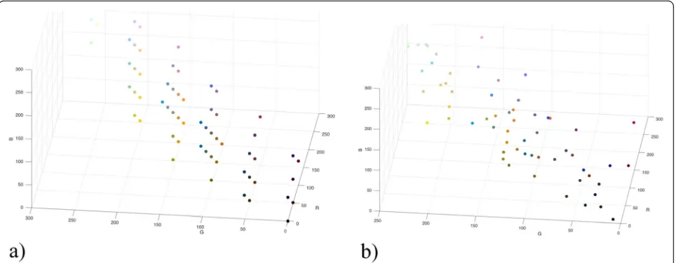
The usage of the standard color palette has disadvan-tages as well. If there are no limitations for color cube size, most blocks for stegomessage embedding will be of size 32 × 32 × 32 and it might cause visual changes be-tween the cover and stegoimage. The color palette is changed (see Fig.7) and might indicate the use of stega-nography in the image as well.
If smoothing is used, the number of colors in the image with the standard palette increases by 28%. This increases the cover image quality as well as stegoimage uses smaller color sub-cubes to embed stegomessage bits; therefore, the stegoimage quality is better too.
4.5 Discussion
The presented steganography method proposes a new approach on how to change the color palette to keep the user perception as well as provide a reasonable capacity to embed a stegomessage. A comparison of the proposed method to existing methods revealed that the proposed method outperforms existing analogs in at least one of measured values (PSNR, SSIM, or embedding capacity). This method provides a better user perception compared to high capacity methods, while its embedding capacity is larger compared to methods with high PSNR and/or SSIM values. The proposed method is in the middle be-tween user perception and capacity.
It is worth to mention that the proposed method is transforming the color palette, rather than separate pixels. Its capacity is very dependent on a color palette (number of colors in the image and color palette distri-bution in color space) and is not influenced by image size (not directly). Therefore, the proposed method ap-plication area should be low-resolution images with a big number of colors (photos). This would allow highlighting the advantages of the proposed method. At the same time, the proposed method will be lacking cap-acity in several color paintings (not photos).
Existing steganalysis methods are not adapted directly to the proposed method. Our analysis showed that the visual perception is good and the embedded message is not noticed in the image. However, the proposed methods are not
resistant to color palette analysis and standard palette images should not be used to limit the steganography identification.
The current version of the proposed method is not adapted to grayscale images as its usage without any limi-tation can cause color appearance after the stegomessage embedding. To minimize this kind of color space disturb-ance, the maximal cube dimensionnshould be minimized to 2. To adapt the method for grayscale image, the new color must be on the diagonal of the RGC cube. There-fore, log2(n) bits should be embedded in n ×n ×n size
sub-cube by repeating the same bits for all three RGB color axes. Only one dimension will be used for grayscale images rather than three dimensions. Such a limitation would assure the smallest changes in the color palette or change into another gray color.
5 Conclusion
The analysis of existing steganography methods revealed that the biggest number of methods is based on pixel modification rather than color palette changes to embed stegomessage. Existing color palette modification methods are not developed enough as one part of them requires some shared data, while the other part uses some complex calculations. We proposed a new steganography method, which is based on image color palette transformation by replacing the location of the color in RGB cube and does not require complex calculations, therefore can be used in mobile or embedded devices too.
method, which would outperform our method based on all embedding quality and capacity metrics.
Experiments with different cover images revealed that the method does not require high-resolution cover im-ages and the pixel, as well as embedding capacity, is higher when lower resolution images are used. If stand-ard or adaptive color palette cover images are used, the average color capability can be increased up to 20 bits per color. This allows embedding averagely 2940 bits of data when adaptive palette with up to 256 colors is used, and it will not add random noise to the image (the color palette will be changed rather than separate pixels).
Abbreviations
c:Contrast comparison function;H: Image height (in pixels);k: The number of possible color location in the image RGB cube;l: Luminance comparison function; LSB: Least significant bit;n: The edge length of the divided RGB cube, with one color inside of it;N: The maximum number of bits, which can be embedded into stegoimage; PSNR: Peak Signal Noise Ratio; PVD: Pixel value differencing; RGB: Red Green Blue;s: Structure comparison function; SCP: Shared color palette; SMK: Seppanen, Makela, and Keskinarkaus; SSIM: Structural Similarity Index;W: Image width (in pixels)
Acknowledgements
No other persons participated in the research.
Authors’contributions
EM was responsible for the method development and implementation. SR prepared the research methodology and wrote the paper. Joint work was used to execute the experiments and to compare the proposed method with other methods. Both authors read and approved the final manuscript.
Authors’information
Eugenijus Margalikas was born in Siauliai, Lithuania, in 1983. He received the B.S. and M.S. degrees in Informatics Engineering from Siauliai University in 2006 and 2016.
Since 2004, he applied his knowledge in several areas such as education and broadcasting. He is currently working as a CNC programmer at Nordisk Massivtre AS, Norway.
Simona Ramanauskaitėis born on December 18, 1983. She received a PhD in Informatics Engineering in 2012 from Vilnius Gediminas Technical University, Lithuania. Currently, she is working as an assoc. prof. at Vilnius Gediminas Technical University. Her current research interests include different aspects of Information Security and Human-Computer Interaction.
Funding
The research had no specific funding and was implemented as a master thesis inŠiauliai Univesity with the supervisor from Vilnius Gediminas Technical University.
Availability of data and materials
Please contact the author for data (in the experiment used images or MatLab files with implemented method) requests.
Competing interests
The authors declare that they have no competing interests.
Author details
1Šiauliai University,Šiauliai, Lithuania.2Vilnius Gediminas Technical University,
Vilnius, Lithuania.
Received: 16 June 2019 Accepted: 3 October 2019
References
1. J. Li, C. Yu, B.B. Gupta, X. Ren, Color image watermarking scheme based on quaternion Hadamard transform and Schur decomposition. Multimed. Tools Appl.77(4), 4545–4561 (2018)
2. Z. Zhang, H. Sun, S. Gao, S. Jin, Self-recovery reversible image watermarking algorithm. PloS One13(6), e0199143 (2018)
3. C. Qin, P. Ji, C.-C. Chang, J. Dong, X. Sun, Non-uniform watermark sharing based on optimal iterative BTC for image tampering recovery. IEEE Multimed.25(3), 36–48 (2018)
4. C. Yung-Fu, S.W. Chien, H.H. Lin, inWSEAS International Conference. Proceedings Mathematics and Computers in Science and Engineering. No. 3. True color image steganography using palette and minimum spanning tree (World Scientific and Engineering Academy and Society, Wisconsin, 2009)
5. B.S. Champakamala, K. Padmini, D.K. Radhika, Least significant bit algorithm for image steganography. Int. J. Adv. Comput. Technol.3(4), 34–38, (2014) 6. S.O. Mundhada, V.K. Shandilya, Spatial and transformation domain
techniques for image enhancement. Int. J. Eng. Sci. Innovative Technol.1(2), 213–216 (2012)
7. C. Bhabatosh,Digital Image Processing and Analysis(PHI Learning Pvt. Ltd., New Delhi, 2011)
8. H.K. Sawant, M. Deore, A comprehensive review of image enhancement techniques. Int. J. Comput. Technol. Electron. Eng.1(2), 39–44 (2010) 9. D.C. Wu, W.H. Tsai, A steganographic method for images by pixel-value
differencing. Pattern Recogn. Lett.24(9), 1613–1626 (2003)
10. X. Li, J. Li, B. Li, B. Yang, High-fidelity reversible data hiding scheme based on pixel-value-ordering and prediction-error expansion. Signal Process.
93(1), 198–205 (2013)
11. H.H. Liu, C.M. Lee, High-capacity reversible image steganography based on pixel value ordering. EURASIP J. Image Video Process.1(2019), 54 (2019) 12. S. Thenmozhi, M. Chandrasekaran, inComputational Intelligence &
Computing Research (ICCIC). Novel approach for image stenography based on integer wavelet transform (2012 IEEE International Conference on. IEEE, Coimbatore, 2012)
13. V. Senthooran, L. Ranathunga, inNetworks & Soft Computing (ICNSC). DCT coefficient dependent quantization table modification
steganographic algorithm (2014 First International Conference on. IEEE, Guntur, 2014)
14. J.A. Mazumder, K. Hemachandran, Color image steganography using discrete wavelet transformation and optimized message distribution method. Int. J. Comput. Sci. Eng.2(7), 90–100 (2014)
15. K. Patel, L. Ragha, inIndustrial Instrumentation and Control (ICIC). Binary image steganography in wavelet domain (2015 International Conference on. IEEE, Pune, 2015)
16. A. Dalvi, R.S. Kamathe, Color image steganography by using dual wavelet transform (DWT, SWT). Int. J. Sci. Eng. Res.3(7), 2347–3878 (2015) 17. H. Huang, Z. Zhou, An image steganography algorithm based on the
quantitative features of higher order local model. Int. J. Secur. Appl.10(7), 83–92 (2016)
18. T. Pevný, T. Filler, P. Bas, inProceedings of Information hiding, Calgary, Canada. Using high-dimensional image models to perform highly undetectable steganography (2010), pp. 161–177
19. S. Sun, A novel edge based image steganography with 2k correction and Huffman encoding. Inf. Process. Lett.116(2), 93–99 (2016)
20. T.D. Nguyen, S. Arch-Int, N. Arch-Int, An adaptive multi bit-plane image steganography using block data-hiding. Multimed. Tools Appl.75(14), 8319– 8345 (2016)
21. C. Yan, L. Li, C. Zhang, B. Liu, Y. Zhang, Q. Dai, Cross-modality bridging and knowledge transferring for image understanding. IEEE Trans. Multimed. 21(10), 2675–2685 (2019)
22. C. Yan et al., A fast Uyghur text detector for complex background images. IEEE Trans. Multimed.20(12), 3389–3398 (2018)
23. T. Seppanen, K. Makela, A. Keskinarkaus, inInternational Workshop on Information Security. Hiding information in color images using small color palettes (Springer, Berlin Heidelberg, 2000)
24. G. Brisbane, R. Safavi-Naini, P. Ogunbona, High-capacity steganography using a shared colour palette. IEEE Proc. Vis. Image Signal Process.152(6), 787–792 (2005)
25. M. Niimi, H. Noda, E. Kawaguchi, R.O. Eason, inPattern Recognition, 2002. Proceedings 16th International Conference on. Luminance quasi-preserving color quantization for digital steganography to palette-based images, vol 1 (IEEE, Quebec City, 2002)
27. K.B. Raja, S. Siddaraju, K.R. Venugopal, L.M. Patnaik, inSignal Processing, Communications and Networking, 2007. Secure steganography using colour palette decomposition (ICSCN'07. International Conference on. IEEE, Chennai, 2007)
28. A. Hore, D. Ziou, inPattern recognition (icpr), 2010 20th international conference on. Image quality metrics: PSNR vs. SSIM (IEEE, Istanbul, 2010) 29. D. Martin, C. Fowlkes, D. Tal, J. Malik,A Database of Human Segmented
Natural Images and its Application to Evaluating Segmentation Algorithms and Measuring Ecological Statistics(2001)
30. “True Color Kodak Images.”[Online]. Available:http://r0k.us/graphics/kodak/. [Accessed 3 Aug 2019]
31. N. Ponomarenko et al., Image database TID2013: Peculiarities, results and perspectives. Signal Process. Image Commun.30, 57–77 (2015) 32. I. Avcibas, N. Memon, B. Sankur, Steganalysis using image quality metrics.
IEEE Trans. Image Process.12(2), 221–229 (2003)
33. J. Fridrich, J. Kodovsky, Rich models for steganalysis of digital images. IEEE Trans. Inf. Forensics Secur7(3), 868–882 (2012)
34. H. Zhao, H. Wang, M.K. Khan, Steganalysis for palette-based images using generalized difference image and color correlogram. Signal Process.91(11), 2595–2605 (2011)
Publisher’s Note