Inhomogeneity of plastic deformation in austenitic stainless steel after surface mechanical attrition treatment
Szymon Bajda1, Wiktoria Ratuszek1, Michal Krzyzanowski1,2, Delphine Retraint3
1 AGH University of Science and Technology, Mickiewicza 30, Krakow 30-059, Poland 2 Birmingham City University, Faculty Computing, Engineering & the Built Environment,
Millenium Point, Curzon Street, Birmingham B4 7XG, UK
3 University of Technology of Troyes, CNRS UMR 6281, Physics, Mechanics, Material and
Nanotechnology Department ICD/LASMIS, 12 rue Marie Curie, 10004 Troyes Cedex, France
Corresponding author: Szymon Bajda, e-mail: sbajda@agh.edu.pl
Abstract
Inhomogeneity of microstructure evolution in cold-rolled austenitic stainless steel after surface mechanical attrition treatment (SMAT) was investigated. A characteristic deformation pattern was obtained for all studied specimens. Selected areas were examined through X-ray diffraction (XRD) and scanning electron microscopy (SEM). Calculations of the α’-martensite volume fraction below the treated surfaces showed, that some of the studied areas are characterised by a few dozen percent different amount of α’-martensite phase. The performed finite element (FE) numerical analysis revealed, that the reason for this may be the presence of an air gap between the impacted material and fixation and also because of the relatively short high stress time duration due to surface inclination during the surface treatment.Annealing at 550 and 650 °C doubled or sometimes tripled the volume fraction of α’-martensite and formed Fe2O3 as well as Fe3O4, whereas annealing at 700 °C resulted in both disappearance of α’-martensite and in reduction of the oxides.
Keywords:
SMAT, austenitic stainless steel, strain-induced martensite, non-uniform deformation, annealing, nanocrystalline structure
Over the past decades, nanostructured and ultrafine-grained metallic materials have attracted considerable interest due to their remarkable improvement of mechanical strength [1– 6]. For this reason, they will probably find many applications in future structural engineering. A disadvantage of such high strength materials is their lowered plasticity. However, this problem can be solved using recently developed ultrasonic-assisted surface mechanical attrition treatment (SMAT) [7–10]. It allows to refine the microstructure only at the surface, preserving the plasticity of the core.
In ultrasonic-assisted SMAT, spherical balls (steel, glass or ceramic) of relatively high hardness are placed in a vibrating chamber, which vibrates with a frequency from 20 Hz to 20 kHz. A sample, which surface is going to be treated, is placed at the upper side of the chamber and impacted by a large amount of flying balls. The kinetic energy of the impacting balls induces high plastic deformation at the specimen’s surface resulting in grain refinement down to the nanometric scale without significant contamination or porosity [11,12]. Moreover, as opposed to conventional shot peening [13,14], in ultrasonic-assisted SMAT random directional impacts of the balls onto the sample surface facilitate the grain refinement process [7].
A nanocrystallised structure can be observed up to several tens of micrometers below the surface and, as the depth increases, a hardened transition zone is observed at the layer of about 200 μm depth characterised by a grain size gradient [8,15–17]. Such limited volume
paper, the microstructure evolution accounting for the inhomogeneity of plastic deformation during ultrasonic-assisted SMAT is studied.
A special emphasis was placed on the study of the strain-induced α’-martensite, as it increases the work-hardening capacity and has substantial influence on ductility of steels [26– 29]. In order to evaluate the possible microstructural changes during thermo-mechanical joining process, annealing studies of SMATed plates were performed at similar temperatures, which are usually used in the second step of duplex technique. It allowed for observation of the relevant changes in α’-martensite volume fraction depending on the heat treatment parameters and the area of the sample under consideration. The amount of α’-martensite significantly increased after annealing at relatively high temperatures proving high thermal stability of this phase in the SMATed material. The thermal stability may influence the bonding mechanisms during thermo-mechanical joining process affecting quality of the multilayered metallic structural materials.
The aim of this work is to investigate the conditions leading to inhomogeneity of plastic deformation in austenitic stainless steel after ultrasonic-assisted SMAT that can significantly affect the microstructure and mechanical properties of the treated material. The influence of non-uniform deformation on the volume content of α’-martensite has been studied. In order to investigate the stress distribution within the steel sample due to ball impact during SMAT, a finite element (FE) analysis was performed.
2. Experimental procedure
The cold rolled 1 mm thickness sheet of AISI 316L austenitic stainless steel with initial grain size of 10 to 50 μm was used in the investigation. Its chemical composition is shown in Table 1. The temperature, at which 50% of the austenite transforms to martensite with 30% true strain Md30, the martensite start temperature Ms and the stacking fault energy (SFE) values for the considered material calculated according to equations based on the chemical composition are presented in Table 2. The SFE was calculated using the equation developed by Bavay [36]:
) (% 2 . 1 ) (% 13 ) (% 77 ) (% 9 . 0 ) (% 410 ) (% 2 7 .
25 Ni C Cr N Si Mn
SFE (1)
Another used empirical equation is proposed by Schramm et al. [37]:
Table 1. Chemical composition of AISI 316L stainless steel (wt.%).
Fe C Si Mn P S Cr Mo Ni N
68.5 0.02 0.488 0.90 0.0315 0.0002 16.998 2.03 11.039 0.0287
Table 2. Md30, Ms and SFE of the studied AISI 316L stainless steel calculated according to the equations of different authors.
Md30, °C reference Ms, °C reference SFE, mJ/m2 reference
-28.5 [36] -162 [38] 31.0 [36]
3.4 [39,40] -150.9 [40,41] 49.1 [37,41] -73.8 [27,42]
For the experimental tests, 130 mm × 110 mm × 1 mm plates were cut. The plates were subjected to SMAT using 3 mm diameter 100Cr6 steel balls for 30 and 35 min at a frequency of 20 kHz. The samples have been treated in air at room temperature. The chamber dimensions allowed for treatment of the surface area of 85 mm × 35 mm.
Fig. 1 The plate after SMAT (two sides: A and B).
and SMATed again over the same period of time until the target treatment duration for both sides is reached. The duration of surface treatment is progressively extended in consecutive steps to increase effectiveness of the process. The material strengthening allows for such operation. Such an approach should presumably allow for obtaining relatively comparable surface shapes for both sides of a sample. In reality, the stresses generated during multiple ball impacts were extremely high, to such extent that obtaining identical profiles for both surfaces wasn’t possible. Instead, an interesting characteristic deformation pattern has been observed
similar for each processed plate. On one surface, a pair of convex area (CA) portions and a single concave valley (CV) were noticed (Fig. 1a), whereas on the other side, a pair of CVs and a single CA were observed (Fig. 1b). The deformed after the SMAT processing steel sample is shown in Fig. 1. The change in shape of any given surface starts to be clearly noticeable after about 5 minute treatment. At earlier stages of such treatment, the accumulated strain is relatively low and the shape of the processed plate is very similar to the initial one. One of the possible explanations of such behaviour can be rapid increase of α’-martensite volume fraction after about 5 minutes of SMAT. Although, the observed phenomenon needs to be examined in greater detail. Then, as the total treatment time increases, the distortion deepens and the level of deformation is stabilised after about 20 minutes.
The initial distance between the sample and the bottom of the chamber was 15 mm. As the plate started to deform, the distance began to change in various ways depending on the considered sample area. Finally, it reached about 12 mm from CAs and about 18 mm from CVs. The specimens representing above mentioned zones were cut from the plate and their surfaces were denoted as A1 for CA and A3 for CV, as can be seen in Fig. 1a. The opposite sides of the cut specimens were marked as B1 (opposite to A1) representing CV and B3 (opposite to A3) representing CA, as it is shown in Fig. 1b. Additionally, a specimen from the area localized between CA and CV was cut and the corresponding surfaces were marked as A2 (Fig. 1a) and B2 (Fig. 1b). These surfaces are inclined at about 45 degree relative to CA and CV planes. All specimens cut in such way were subjected to SEM and X-ray diffraction (XRD) investigation.
SEM observations were performed using a JEOL JSM-6460LV electron microscope at an accelerating voltage of 15 kV. The cross-sections of the samples have been subjected to reactive ion etching.
A PANalitycal Empyrean diffractometer with copper radiation Kα = 1.5418 Å was
on surfaces using the Bragg-Brentano (BB) and grazing incidence (GIXD, α = 3°) geometries. BB method allowed to study the average microstructure changes up to 7 μm distance below a surface. In GIXD the distance was exactly 0.72 μm, as the incidence angle α = 3° was applied. After the SMAT, the two phases were identified and the volume fractions of austenite (γ) and α’-martensite phases were calculated using Rietveld analysis. BB and GIXD methods allowed
to determine volume fractions of γ and α’-martensite depending on the depth below the surface. XRD analysis was also used to study specimens annealed at 550, 650 and 700 °C for 30 minutes. For this purpose, the infrared furnace heater of high precision was employed. It allowed uniform heating of the whole sample due to no contact between the specimen and the substrate of the chamber. Moreover, the heater allowed for maintaining the right temperature precisely within +/- 0.5 °C limits.
The micro hardness measurements were performed at the cross-sections of the specimens below the SMATed surfaces using the Vickers micro hardness tester Nova 330/360 Series. The indentation load was selected as 25 grams with a dwell time of 15 seconds. In order to obtain an accurate hardness profile, three indentations were applied at the same depth from the treated surface. Neighbouring indentations were separated by a distance of at least 25 μm to avoid erroneous measurements due to the affected plastic zone around an indent.
3. Mechanism of grain refinement in austenitic stainless steel
The mechanism of surface nanocrystallization has been studied for various austenitic stainless steel grades. One of the most studied grades is 304 SS, for which the grain refinement process is based on formation of the planar dislocations arrays and twins; on twin-twin intersections leading to grain subdivision and martensite transformation; and on formation of randomly oriented crystallites [47]. The SFE of 304 SS is rather low, hence the twinning based mechanism is likely to be dominant. The polycrystalline austenitic stainless steel studied in this work (316L SS) had significantly higher SFE (Table 2), favouring an expectation of the different grain refinement mechanisms. It has been reported recently, that nanocrystallization in materials with medium SFE may occur due to dynamic recrystallization and recrystallization twinning in shear bands. The ultrafine recrystallized grains are divided into cells being transformed into nanocrystalline grains by increasing misorientation under continuous deformation [48].
4.1 The cross-sectional morphology
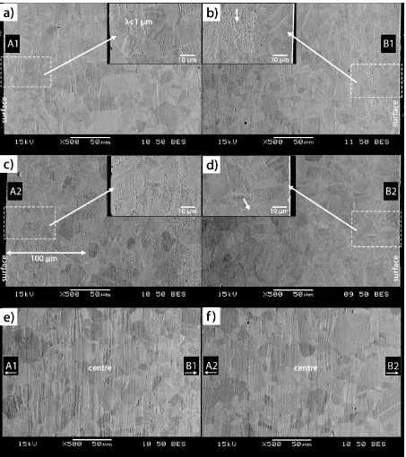
SEM observations of the steel morphology were made using the specimen cross-sections. Fig. 2a-d illustrates the obtained microstructures under A1, B1, A2 and B2 surfaces subjected to SMAT for 30 min. Microstructures under A3 and B3 surfaces are very similar, hence they were not shown. It can be seen, that there are no significant differences in the cross-sectional morphology between each of the surfaces of the treated steel sample. The noticeable changes of microstructure occur at areas situated about 100 μm below the surface, and are characterised by a large number of aligned deformation bands. As can be seen in Fig. 2a, the distance λ between the vast majority of deformation bands is below 1 μm indicating relatively
Fig. 2 SEM images of the cross-sections obtained from the samples after 30 min of SMAT and
localised at CA (a), CV (b), at the inclined region localised between them (c-d) and at the
sample centre between A1 and B1 (e), and also between A2 and B2 (f) surfaces.
be concluded that corrugated structure is typically formed in the areas where high comparable pressure acts in opposite directions from both surfaces of the specimen. Such areas are located in the centre of the sample.
Fig. 3 illustrates the cross-sectional SEM image of microstructure obtained from the samples subjected to SMAT for 35 min. SEM micrographs of the area below A2 (Fig. 2c) and B2 (Fig. 2d) surfaces indicates, that microstructure is changed at the surface layer of up to 100 μm depth after 30 minutes of SMAT. However, relatively little longer processing time, such as 35 minutes, resulted in over 50% increase of the affected depth for the area both under A2 (Fig. 3) and B2 surfaces. The microstructure illustrated in Fig. 3 is characterised by deformation band intersections. The results of Balusamy et al. [50] related to SMAT of 304 SS show that the affected region visible on optical and SEM micrographs reaches about 150 μm for 8 mm
diameter balls, 50 Hz frequency of vibration and 60 minutes of SMAT duration. In other studies of Balusamy et al. [49,51], the optical micrographs of the same material are shown indicating that for the same frequency of vibration, 8 mm diameter balls and 15 minutes of SMAT duration the thickness of the deformed region decreased to 110 μm. Changing the diameter of the balls to 5 mm and setting the SMAT duration to 30 and 45 minutes resulted in obtaining of the modified surface layer correspondingly of 72 and 82 μm thickness. Further decrease of the ball diameter to 2 mm let to formation of 48 and 59 μm thick layers respectively after 30 and 60
minutes of SMAT. Samih et al. [8] studied the affected depth of 316L SS after SMAT with various parameters, constant 1 mm diameter of the balls and 20 kHz frequency of vibration. The EBSD maps and the associated quantification of the geometrically necessary dislocation densities were employed to identify the deformed microstructure. The affected depth was 175 and 220 μm after correspondingly 3 and 20 minutes of SMAT with 80 μm amplitude of the
vibrating sonotrode. However, the results obtained using the mentioned powerful research methods allow to identify microstructure changes to a greater depth than from an optical and SEM micrographs. Hence, identification of the effected thickness from hardness measurements seems to be more appropriate for such comparison. Gatey et al. [52] studied the mentioned effects on 304L SS subjected to SMAT under 100 Hz frequency of vibration and 15 mm gap between the sample and the bottom of the chamber. The affected depth, determined by the hardness measurements, was 250, 250 and 330 μm respectively after correspondingly 15, 30
and 60 minutes of SMAT using balls of 3 mm diameter. For 8 mm diameter of the balls and 60 minutes of SMAT, the affected depth increased up to 430 μm.
kHz frequency of vibration and 15 mm initial gap between the sample and the bottom of the chamber (Fig. 7). The similar results for 316L SS were obtained by Sun et al. [53] applying identical SMAT processing parameters.
Fig. 3 SEM image of the cross-section obtained from the area A2 localized between
CA and CV of the sample subjected to SMAT for 35 min.
4.2 XRD measurements
Fig. 4 XRD patterns obtained from the samples subjected to 30 min SMAT in comparison with
untreated material representing CAs, CVs and the inclined region localised between them
beneath the A1, A3 and A2 surfaces respectively. XRD patterns were obtained using BB and
GIXD (α=3°) methods.
formation of the randomly oriented nanocrystallites at the surface (Fig. 4, GIXD) and texture reduction at deeper layers (Fig. 4, BB). The mechanism responsible for this can be the grain boundary sliding and/or grain rotation, occurring in other severe plastic deformation processes [54] and leading to martensitic transformation and grain refinement. The phase analysis showed about 5% of ferrite in the untreated material.
The relative intensities obtained by GIXD and BB methods clearly indicate that the volume fraction of α’-martensite decreases with depth. XRD patterns showed significant
decrease in intensity from γ(220) plane after γ→α’ phase transformation. The α’-martensite intensities of α’(110) planes under A2 surface, which is identified as an inclined region localised between the CA and CV, are relatively lower in comparison with the corresponding intensities obtained for CA and CV regions. A similar phenomenon has been observed in the samples after 35 minutes of SMAT. Furthermore, comparable effects are observed in the diffractograms taken from the samples localised under B2 surfaces (not shown). The corresponding α’-martensite volume fractions were calculated using Rietveld analysis of XRD patterns and are shown in Table 3.
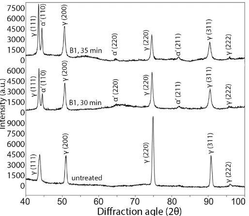
Fig. 5 XRD patterns obtained for CVs localised at B1 surfaces after 30 and 35 minutes of
SMAT. BB geometry was used.
plastic deformation of the formed α’-martensite. The α’-martensite formation takes place at the expense of austenite grains of certain crystallographic orientations [55]. Fig. 5 illustrates the XRD patterns obtained for B1 surfaces after 30 and 35 minutes of SMAT. It can be noticed, that the relative intensity from α’-martensite α’(110) plane is significantly higher for longer processing duration. Consequently, the austenite peaks from γ(220) and γ(311) are smaller for 35 minutes than for 30 minutes duration of the treatment. Moreover, the relative intensities from austenite γ(111) plane increased after the SMAT, which indicates the change in crystallites orientation. The relative intensity from the austenite γ(220) plane drastically decreased after the processing implying that: (i) the martensitic transformation primarily occurs at the expense of the grains with this orientation, (ii) the rotation of the γ(220) grains takes place causing initial texture reduction.
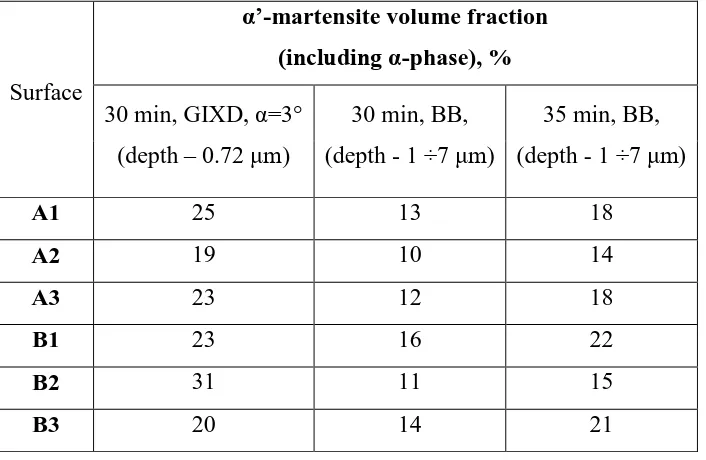
Table 3. The α’-martensite volume fractions for A1, A2, A3, B1, B2 and B3 surfaces obtained using BB and GIXD geometry after 30 and 35 minutes of SMAT. Ferrite (α-phase) content of untreated material is included.
Surface
α’-martensite volume fraction (including α-phase), % 30 min, GIXD, α=3°
(depth – 0.72 μm)
30 min, BB, (depth - 1 ÷7 μm)
35 min, BB, (depth - 1 ÷7 μm)
A1 25 13 18
A2 19 10 14
A3 23 12 18
B1 23 16 22
B2 31 11 15
B3 20 14 21
surface after 30 minutes of SMAT. The origin of this phenomenon is not clear. Only 5 minutes longer SMAT generated a significant increase of α’-martensite content (about 40% on average)
for all of the studied specimens in comparison with those produced under 30 minutes processing time.
It is believed, that SMAT always generates beneficial compressive residual stresses [56– 59]. However, preliminary studies of γ and α’-martensite phases using g-sin2ψ method [60,61] have shown that depending on the specific area under consideration, the residual stresses may be compressive or tensile. The advantage of application of g-sin2ψ geometry is the constant penetration depth when interplanar spacings are measured for different orientations of the scattering vector. The approach allows for precise determination of the measurement region as opposed to conventional sin2ψ and ω-sin2ψ methods. Further extensive research is required for more detailed characterization of the residual stresses in such inhomogeneously deformed materials. The average crystallite size, obtained by BB method, for all specimens after SMAT was about 23 nm for austenite and about 33 nm for α’-martensite.
4.3 XRD measurements after sample annealing
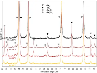
Fig. 6 XRD patterns obtained for CAs localised at A1 surfaces after 30 minutes of SMAT and
30 minutes of annealing at different temperatures. BB geometry was applied.
The volume fraction of Fe2O3 and Fe3O4 was 10-20% and 1-2% respectively for all specimen surfaces treated both at 550 and 650 °C. After annealing at 700 °C, the Fe2O3 and Fe3O contents have been reduced to almost zero level.
Table 4. The α’-martensite, hematite and magnetite volume fractions for A1, A2 and B2 surfaces obtained using BB method after 30 minutes of SMAT and 30 minutes of annealing at different temperatures.
Surface Temperature
volume fraction, % α’-martensite
(α-phase included)
Fe2O3 Fe3O4
A1 550 °C 43 18 2.5
650 °C 28 20 1
A2 550 °C 44 14 1
650 °C 47 21 2
B2 550 °C 33 12 1
650 °C 46 10 2
4.4 Hardness measurements
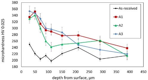
Fig. 7 Variation of cross-sectional Vickers micro-hardness beneath the A1, A2 and A3
surfaces after 30 minutes of SMAT.
4.5 Numerical modelling
Modelling of conventional shot peening is complicated due to involvement of the metal surface layer interacting with a large number of ball impacts [63]. Modelling of the ultrasonic-assisted SMAT is even more difficult due to variations of the shot velocity and also because of the randomly directed impacts on the surface [64]. Therefore, the shot velocity during SMAT is generally assumed as a constant [58,65]. Moreover, modelling of the multiple impacts requires significant amount of both CPU time and operational memory. Hence, the simplified numerical analysis of a single ball impact on the material surface has been performed in this work.
0
ln 1
C B
A n (3)
where is the equivalent stress, A is the initial yield strength of the material at room temperature, B is the strain hardening coefficient, C is the strain rate sensitivity, is the
equivalent plastic strain, is the plastic strain rate, 0 is the reference strain rate for a
quasi-static test and n is the work-hardening exponent. Due to lack of relevant data for 316L SS, the corresponding parameters relevant to the similar 304 SS were used in the investigation. The following parameters defining the constitutive equation have been applied for the modelling: A
= 310 MPa, B = 1000 MPa, C = 0.07, 0 = 1 s-1, n = 0.65 [67]. The modulus of elasticity,
Poisson’s ratio and density of the deformed material was assumed as 193 GPa, 0.25 and 7758
Fig. 8 The equivalent stress distribution predicted at the specimen’s cross-section during the
ball impact on the A1 (a), A2 (b) and A3 (c) surfaces.
between the CA and CV (Fig. 8b) and of the CV (Fig. 8c). The contour maps were obtained for each case at the time moment t, in which relatively high stresses start to appear in the material. The influence of modelled air gaps on the stress distribution within the material impacted by a ball is examined. The results presented in Fig. 8a and 8c, where the only difference is that there is an air gap in the first case, indicate that the stresses generated inside the material during single ball impact at an angle of 90 degrees to the surface are lower when such air gap is present. In Fig. 8a and 8b, the air gaps are present in both cases with the difference that the surface is inclined at an angle of 45 degree relative to CA and CV planes in the second case. Comparing the presented results, it can be noticed that the calculated stresses are little smaller for the inclined region at a time moment t than those calculated at CA. However, a significant difference in the calculated stress levels is observed after time Δt, which has been assumed equal in both cases, when the stresses generated in the inclined region are considerably reduced. From these considerations, it was learned that both the presence of air gaps lowering stresses and the relatively short time duration of high stresses due to the surface inclination, acting simultaneously, may contribute toward the observed experimentally lowering of the α’-martensite volume fractions under the A2 and B2 surfaces. There is a large number of impacts from the balls with respect to the metal surface that takes place in the real SMAT process. Each impact induces notably smaller stresses for any inclined region. Therefore, the overall stress distribution in such areas will be significantly different compared to the one observed at CA and CV regions.
5. Conclusions
Inhomogeneity of plastic deformation in cold-rolled 316L austenitic stainless steel after ultrasonic-assisted SMAT has been studied. In this work, a textured surface was taken into account. The detailed XRD investigation combining BB and GIXD geometries allowed for non-destructive studies carried out at different material depths. Evaluation of the α’-martensite volume fraction in different areas of the treated specimens was the central point in the present study.
SMAT may affect bonding mechanisms during second subsequent step of the duplex processing affecting microstructure evolution around the interface. In order to produce high quality multilayered material, it is important to understand the influence of such inhomogeneous deformation, which was the subject of the current work. The following significant differences in microstructure depending on the specific areas under consideration and the treatment duration time have been noticed and discussed:
The inclined regions below the A2 and B2 surfaces are generally characterised by lower amount of α’-martensite.
Elongation of the SMAT duration time from 30 to 35 minutes caused about 40% increase of α’-martensite volume fraction at all considered areas.
The current studies indicated that the residual stresses may be either compressive or tensile depending on the specific area under consideration.
SEM investigations revealed large areas of corrugated structure at the centre of the samples typical for all specimens.
The numerical analysis showed, that presence of air gaps between the impacted material and fixation and also relatively short high stress time duration due to surface inclination favoured overall stresses reduction in the material during the ball impact, which can be the reason for the observed reduction of α’-martensite volume fraction.
Annealing at both 550 and 650 °C caused considerable increase of α’-martensite phase.
Acknowledgements
References:
[1] H. Gleiter, Nanocrystalline materials, Prog. Mater. Sci. 33 (1989) 223–315. doi:10.1016/0079-6425(89)90001-7.
[2] C. Suryanarayana, Nanocrystalline materials, Int. Mater. Rev. 40 (1995) 41–64. doi:10.1179/095066095790151106.
[3] S.C. Tjong, H. Chen, Nanocrystalline materials and coatings, Mater. Sci. Eng. R Reports. 45 (2004) 1–88. doi:10.1016/j.mser.2004.07.001.
[4] M.A. Meyers, A. Mishra, D.J. Benson, Mechanical properties of nanocrystalline materials, Prog. Mater. Sci. 51 (2006) 427–556. doi:10.1016/j.pmatsci.2005.08.003. [5] C.C. Koch, Structural nanocrystalline materials: An overview, J. Mater. Sci. 42 (2007)
1403–1414. doi:10.1007/s10853-006-0609-3.
[6] M. Vedani, P. Bassani, A. Tuissi, G. Angella, Ultrafine grained alloys produced by severe plastic deformation: issues on microstructural control and mechanical behaviour, Metall. Sci. Technol. 22 (2004) 21–30.
http://www.gruppofrattura.it/ors/index.php/MST/article/view/1108.
[7] K. Lu, J. Lu, Nanostructured surface layer on metallic materials induced by surface mechanical attrition treatment, Mater. Sci. Eng. A. 375–377 (2004) 38–45.
doi:10.1016/j.msea.2003.10.261.
[8] Y. Samih, B. Beausir, B. Bolle, T. Grosdidier, In-depth quantitative analysis of the microstructures produced by Surface Mechanical Attrition Treatment ( SMAT ), Mater. Charact. 83 (2013) 129–138. doi:10.1016/j.matchar.2013.06.006.
[9] T. Roland, D. Retraint, K. Lu, J. Lu, Enhanced mechanical behavior of a
nanocrystallised stainless steel and its thermal stability, Mater. Sci. Eng. A. 445–446 (2007) 281–288. doi:10.1016/j.msea.2006.09.041.
[10] Z. Sun, D. Retraint, T. Baudin, A.L. Helbert, F. Brisset, M. Chemkhi, J. Zhou, P. Kanouté, Materials Characterization Experimental study of microstructure changes due to low cycle fatigue of a steel nanocrystallised by Surface Mechanical Attrition
Treatment ( SMAT ), Mater. Charact. 124 (2017) 117–121. doi:10.1016/j.matchar.2016.12.017.
[11] G. Liu, J. Lu, K. Lu, Surface nanocrystallization of 316L stainless steel induced by ultrasonic shot peening, Mater. Sci. Eng. A. 286 (2000) 91–95. doi:10.1016/S0921-5093(00)00686-9.
Technol. 20 (2004) 55–58.
[13] H. Kumar, S. Singh, P. Kumar, Modified Shot Peening Processes - A Review, Int. J. Eng. Sci. Emerg. Technol. 5 (2013) 12–19. doi:10.3221/IGF-ESIS.07.01.
[14] M. Thomas, M. Jackson, The role of temperature and alloy chemistry on subsurface deformation mechanisms during shot peening of titanium alloys, Scr. Mater. 66 (2012) 1065–1068. doi:10.1016/j.scriptamat.2012.02.049.
[15] N.R. Tao, Z.B. Wang, W.P. Tong, M.L. Sui, J. Lu, K. Lu, An investigation of surface nanocrystallization mechanism in Fe induced by surface mechanical attrition treatment, Acta Mater. 50 (2002) 4603–4616. doi:10.1016/S1359-6454(02)00310-5.
[16] J. Petit, L. Waltz, G. Montay, D. Retraint, A. Roos, M. François, Multilayer modelling of stainless steel with a nanocrystallised superficial layer, Mater. Sci. Eng. A. 536 (2012) 124–128. doi:10.1016/j.msea.2011.12.085.
[17] L. Wang, Z. Wang, S. Guo, K. Lu, Annealing-induced Grain Refinement in a Nanostructured Ferritic Steel, J. Mater. Sci. Technol. 28 (2012) 41–45. doi:10.1016/S1005-0302(12)60021-8.
[18] L. Waltz, D. Retraint, A. Roos, P. Olier, Combination of surface nanocrystallization and co-rolling: Creating multilayer nanocrystalline composites, Scr. Mater. 60 (2009) 21–24. doi:10.1016/j.scriptamat.2008.08.024.
[19] S. Bajda, M. Krzyzanowski, K. Muszka, W.M. Rainforth, Numerical analysis of highly reactive interfaces in processing of nanocrystallised multilayered metallic materials by using duplex technique, Surf. Coatings Technol. 277 (2015) 170–180.
doi:10.1016/j.surfcoat.2015.07.019.
[20] L. Waltz, D. Retraint, A. Roos, C. Garnier, P. Olier, Effect of interfacial oxidation occurring during the duplex process combining surface nanocrystallisation and co-rolling, Surf. Coatings Technol. 205 (2011) 4608–4613.
doi:10.1016/j.surfcoat.2011.03.140.
[21] D. Retraint, M.Z. Quadir, W.Q. Xu, L. Waltz, M. Ferry, Microstructural Investigation of Co-Rolled Nanocrystalline Stainless Steel Sheets, Mater. Sci. Forum. 702–703 (2011) 127–130. doi:10.4028/www.scientific.net/MSF.702-703.127.
[22] T. Roland, D. Retraint, K. Lu, J. Lu, Generation of nanostructures on 316L stainless steel and its effect on mechanical behavior, Mater. Sci. Forum. 490–491 (2005) 625– 630. doi:10.4028/www.scientific.net/MSF.490-491.625.
[24] N. Li, S. Shi, J. Luo, J. Lu, N. Wang, Effects of surface nanocrystallization on the corrosion behaviors of 316L and alloy 690, Surf. Coatings Technol. 309 (2017) 227– 231. doi:10.1016/j.surfcoat.2016.11.052.
[25] A.Y. Chen, H.H. Ruan, J. Wang, H.L. Chan, Q. Wang, Q. Li, J. Lu, The influence of strain rate on the microstructure transition of 304 stainless steel, Acta Mater. 59 (2011) 3697–3709. doi:10.1016/j.actamat.2011.03.005.
[26] G. Huang, D. Matlock, G. Krauss, Martensite formation, strain rate sensitivity, and deformation behavior of type 304 stainless steel sheet, Metall. Mater. Trans. A. 20 (1989) 1239–1246. doi:10.1007/BF02647406.
[27] J. Talonen, P. Nenonen, G. Pape, H. Hänninen, Effect of strain rate on the strain-induced γ, → α′-martensite transformation and mechanical properties of austenitic
stainless steels, Metall. Mater. Trans. A Phys. Metall. Mater. Sci. 36 A (2005) 421– 432. doi:10.1007/s11661-005-0313-y.
[28] J. Talonen, H. Hänninen, Formation of shear bands and strain-induced martensite during plastic deformation of metastable austenitic stainless steels, Acta Mater. 55 (2007) 6108–6118. doi:10.1016/j.actamat.2007.07.015.
[29] W. Ratuszek, J. Kowalska, A. Bunsch, M. Rumiński, A. Zielińska-Lipiec,
Development of deformation texture of austenitic steel wires, Arch. Metall. Mater. 53 (2008) 167–174.
[30] M.A. Meyers, Y.B. Xu, Q. Xue, M.T. Pérez-Prado, T.R. McNelley, Microstructural evolution in adiabatic shear localization in stainless steel, Acta Mater. 51 (2003) 1307– 1325. doi:10.1016/S1359-6454(02)00526-8.
[31] J. Kowalska, W. Ratuszek, M. Witkowska, A. Zielińska-Lipiec, M. Kowalski,
Microstructure And Texture Evolution During Cold-Rolling In The Fe-23Mn-3Si-3Al Alloy, Arch. Metall. Mater. 60 (2015) 1789–1794. doi:10.1515/amm-2015-0306. [32] L.E. Murr, K.P. Staudhammer, S.S. Hecker, Effects of Strain State and Strain Rate on
Deformation-Induced Transformation in 304 Stainless Steel : Part II. Microstructural Study, Metall. Trans. A. 13 (1982) 627–635. doi:10.1007/BF02644428.
[33] P.L. Mangonon Jr, G. Thomas, Structure and properties of thermal-mechanically treated 304 stainless steel, Metall. Trans. 1 (1970) 1587–1594.
doi:10.1007/BF02642004.
[34] G.B. Olson, M. Cohen, Kinetics of Strain Induced Martensitic Nucleation, Metall. Trans. A. 6 A (1975) 791–795. doi:10.1007/BF02672301.
doi:10.1179/030634582790427082.
[36] J. C. Bavay, Les editions de physique, in: France, 1993.
[37] R.E. Schramm, R.P. Reed, Stacking fault energies of seven commercial austenitic stainless steels, Metall. Trans. A. 6 (1975) 1345–1351. doi:10.1007/BF02641927. [38] A.F. Padilha, P.R. Rios, Decomposition of Austenite in Austenitic Stainless Steels, ISIJ
Int. 42 (2002) 325–327. doi:10.2355/isijinternational.42.325.
[39] T. Angel, Formation of Martensite in Austenitic Stainless Steels Effect of Deformation, Temperature and Composition, J. Iron Steel Inst. 177 (1954) 165–174.
[40] W. Hübner, Phase transformations in austenitic stainless steels during low temperature tribological stressing, Tribol. Int. 34 (2001) 231–236.
doi:10.1016/S0301-679X(01)00006-8.
[41] A.F. Padilha, R.L. Plaut, P.R. Rios, Annealing of Cold-worked Austenitic Stainless Steels., ISIJ Int. 43 (2003) 135–143. doi:10.2355/isijinternational.43.135.
[42] K. Nohara, Y. Ono, N. Ohashi, Composition and Grain Size Dependencies of Strain-induced Martensitic Transformation in Metastable Austenitic Stainless Steels, Tetsu-to-Hagane. 63 (1977) 772–782.
[43] B.D. Cullity, Elements of X-ray diffraction, 2nd edition, Addison-Wesley Publ. Co. Read. MA. (1978) 100-105-279.
[44] T. Ungár, J. Gubicza, G. Ribárik, A. Borbély, Crystallite size distribution and
dislocation structure determined by diffraction profile analysis: Principles and practical application to cubic and hexagonal crystals, J. Appl. Crystallogr. 34 (2001) 298–310. doi:10.1107/S0021889801003715.
[45] L.B. McCusker, R.B. Von Dreele, D.E. Cox, D. Louër, P. Scardi, Rietveld refinement guidelines, J. Appl. Crystallogr. 32 (1999) 36–50. doi:10.1107/S0021889898009856. [46] H.M. Rietveld, Line profiles of neutron powder-diffraction peaks for structure
refinement, Acta Crystallogr. 22 (1967) 151–152. doi:10.1107/S0365110X67000234. [47] H.W. Zhang, Z.K. Hei, G. Liu, J. Lu, K. Lu, Formation of nanostructured surface layer
on AISI 304 stainless steel by means of surface mechanical attrition treatment, Acta Mater. 51 (2003) 1871–1881. doi:10.1016/S1359-6454(02)00594-3.
[48] S. Bahl, S. Suwas, T. Ungar, K. Chatterjee, Elucidating microstructural evolution and strengthening mechanisms in nanocrystalline surface induced by surface mechanical attrition treatment of stainless steel, Acta Mater. 122 (2017) 138–151.
doi:10.1016/j.actamat.2016.09.041.
Mater. Charact. 85 (2013) 38–47. doi:10.1016/j.matchar.2013.08.009.
[50] T. Balusamy, T.S.N.S. Narayanan, K. Ravichandran, I. Song, M. Ho, Effect of surface mechanical attrition treatment ( SMAT ) on pack boronizing of AISI 304 stainless steel, Surf. Coat. Technol. 232 (2013) 60–67. doi:10.1016/j.surfcoat.2013.04.053. [51] T. Balusamy, T.S.N. Sankara Narayanan, K. Ravichandran, I.S. Park, M.H. Lee,
Influence of surface mechanical attrition treatment (SMAT) on the corrosion behaviour of AISI 304 stainless steel, Corros. Sci. 74 (2013) 332–344.
doi:10.1016/j.corsci.2013.04.056.
[52] A.M. Gatey, S.S. Hosmani, R.P. Singh, Surface mechanical attrition treated AISI 304L steel: role of process parameters, Surf. Eng. 32 (2016) 69–78.
doi:10.1179/1743294415Y.0000000056.
[53] Z. Sun, M. Chemkhi, P. Kanouté, D. Retraint, Fatigue properties of a biomedical 316L steel processed by surface mechanical attrition, IOP Conf. Ser. Mater. Sci. Eng. 63 (2014) 12021. doi:10.1088/1757-899X/63/1/012021.
[54] M. Murayama, Atomic-Level Observation of Disclination Dipoles in Mechanically Milled, Nanocrystalline Fe, Science (80-. ). 295 (2002) 2433–2435.
doi:10.1126/science.1067430.
[55] W. Ratuszek, J. Kowalska, J. Ryś, M. Rumiński, The effect of (γ → α’) phase transformation on texture development in metastable austenitic steel, Arch. Metall. Mater. 53 (2008) 213–219.
[56] V. Llaneza, F.J. Belzunce, Study of the effects produced by shot peening on the surface of quenched and tempered steels: Roughness, residual stresses and work hardening, Appl. Surf. Sci. 356 (2015) 475–485. doi:10.1016/j.apsusc.2015.08.110.
[57] A. Prakash, H.N. Bar, S. Sivaprasad, S. Tarafder, J.P. Dwivedi, The Effect of Residual Stress on Fatigue crack growth rate in AISI 304LN Stainless Steel, Mater. Today Proc. 4 (2017) 677–686. doi:10.1016/j.matpr.2017.01.072.
[58] A. Heydari Astaraee, R. Miresmaeili, S. Bagherifard, M. Guagliano, M. Aliofkhazraei, Incorporating the principles of shot peening for a better understanding of surface mechanical attrition treatment (SMAT) by simulations and experiments, Mater. Des. 116 (2017) 365–373. doi:10.1016/j.matdes.2016.12.045.
[59] T. Roland, D. Retraint, K. Lu, J. Lu, Fatigue life improvement through surface nanostructuring of stainless steel by means of surface mechanical attrition treatment, Scr. Mater. 54 (2006) 1949–1954. doi:10.1016/j.scriptamat.2006.01.049.
427–435. doi:10.1107/S0021889801005404.
[61] A. Baczmanski, C. Braham, W. Seiler, N. Shiraki, Multi-reflection method and grazing incidence geometry used for stress measurement by X-ray diffraction, Surf. Coatings Technol. 182 (2004) 43–54. doi:10.1016/j.surfcoat.2003.07.005.
[62] F. Gauzzi, R. Montanari, G. Principi, M.E. Tata, AISI 304 steel: anomalous evolution of martensitic phase following heat treatments at 400 °C, Mater. Sci. Eng. A. 438–440 (2006) 202–206. doi:10.1016/j.msea.2006.02.116.
[63] B. Bhuvaraghan, S.M. Srinivasan, B. Maffeo, R.D. Mcclain, Y. Potdar, O. Prakash, Shot peening simulation using discrete and finite element methods, Adv. Eng. Softw. 41 (2010) 1266–1276. doi:10.1016/j.advengsoft.2010.09.003.
[64] F. Yin, M. Rakita, S. Hu, Q. Han, Overview of ultrasonic shot peening, Surf. Eng. 0 (2017) 1–16. doi:10.1080/02670844.2017.1278838.
[65] T. Chaise, J. Li, D. Nélias, R. Kubler, S. Taheri, G. Douchet, V. Robin, P. Gilles, Modelling of multiple impacts for the prediction of distortions and residual stresses induced by ultrasonic shot peening ( USP ), J. Mater. Process. Tech. 212 (2012) 2080– 2090. doi:10.1016/j.jmatprotec.2012.05.005.
[66] G.R. Johnson, W.H. Cook, A constitutive model and data for metals subjected to large strains, high strain rates and high temperatures, 7th Int. Symp. Ballist. (1983) 541–547. doi:10.1038/nrm3209.
[67] S. Lee, F. Barthelat, J.W. Hutchinson, H.D. Espinosa, Dynamic failure of metallic pyramidal truss core materials - Experiments and modeling, Int. J. Plast. 22 (2006) 2118–2145. doi:10.1016/j.ijplas.2006.02.006.