R E S E A R C H
Open Access
Design and FPGA implementation of a wireless
hyperchaotic communication system for
secure real-time image transmission
Said Sadoudi
1, Camel Tanougast
2*, Mohamed Salah Azzaz
1and Abbas Dandache
2Abstract
In this paper, we propose and demonstrate experimentally a new wireless digital encryption hyperchaotic
communication system based on radio frequency (RF) communication protocols for secure real-time data or image transmission. A reconfigurable hardware architecture is developed to ensure the interconnection between two field programmable gate array development platforms through XBee RF modules. To ensure the synchronization and encryption of data between the transmitter and the receiver, a feedback masking hyperchaotic synchronization technique based on a dynamic feedback modulation has been implemented to digitally synchronize the encrypter hyperchaotic systems. The obtained experimental results show the relevance of the idea of combining XBee (Zigbee or Wireless Fidelity) protocol, known for its high noise immunity, to secure hyperchaotic communications. In fact, we have recovered the information data or image correctly after real-time encrypted data or image transmission tests at a maximum distance (indoor range) of more than 30 m and with maximum digital modulation rate of 625,000 baud allowing a wireless encrypted video transmission rate of 25 images per second with a spatial resolution of 128×128 pixels. The obtained performance of the communication system is suitable for secure data or image transmissions in wireless sensor networks.
Introduction
Over the past decades, the confidentiality of multime-dia communications such as audio, images, and video has become increasingly important since communications of digital products over the network (wired/wireless) occur more frequently [1,2]. Therefore, the need for secure data and transmission is increasing dramatically and defined by the required levels of security depending on the purpose of communication. To meet these requirements, a wide variety of cryptographic algorithms have been proposed.
In this context, the main challenge of stream cipher cryptography relates to the generation of long unpre-dictable key sequences. More precisely, the sequence has to be random, its period must be large, and the various patterns of a given length must be uniformly distributed over the sequence.
*Correspondence: [email protected]
2Équipe ASEC - Laboratoire Conception, Optimisation et Modélisation des Systèmes, Université de Lorraine, Metz, France
Full list of author information is available at the end of the article
Traditional ciphers like DES, 3DES, IDEA, RSA, or AES are less efficient for real-time secure multimedia data encryption systems and exhibit some drawbacks and weakness in the high stream data encryption [3,4]. Indeed, the increase and availability of a high-power computa-tion machine allow a force brute attack against these ciphers. Moreover, for some applications which require a high-level computation and where a large computational time and high computing power are needed (for example, encryption of large digital images), these cryptosystems suffer from low-level efficiency [5]. Consequently, these encryption schemes are not suitable for many high-speed applications due to their slow speed in real-time pro-cessing and some other issues such as in the handling of various data formatting.
Over the recent years, considerable researches have been taken to develop new chaotic or hyperchaotic sys-tems and for their promising applications in real-time encryption and communication [6-8]. In fact, it has been shown that chaotic systems are good candidates for designing cryptosystems with desired properties [9].
superior performance cryptosystems, and the properties of chaotic maps such as sensitivity to initial conditions and random-like behavior have attracted the attention to develop data encryption algorithms suitable for secure multimedia communications. Until recently, chaotic com-munication has been a subject of major interest in the field of wireless communications. Many techniques based on chaos have been proposed such as additive chaos masking (ACM) [10], where the analog message signal is added to the output of the chaos generator within the transmitter. In [11], chaos shift keying is used where the binary message signal selects the carrier signal from two or more different chaotic attractors. Authors in [12] use chaotic modulation where the message information mod-ulates a parameter of the chaotic generator. Chaos control methods [13,14] rely on the fact that small perturba-tions cause the symbolic dynamics of a chaotic system to track a prescribed symbol sequence. In [15], the receiver system is designed in an inverse manner to ensure the recovery of the encryption signal. An impulsive synchro-nization scheme [16] is employed to synchronize chaotic transmitters and receivers. However, all of these tech-niques do not provide a real and practical solution to the challenging issue of chaotic communication which is based on extreme sensitivity of chaotic synchroniza-tion to both the additive channel noise and parameter mismatches. Precisely, since chaos is sensitive to small variations of its initial conditions and parameters, it is very difficult to synchronize two chaotic systems in a communication scheme. Some proposed synchronization techniques have improved the robustness to parame-ter mismatches as reported in [16,17], where impulsive chaotic synchronization and an open-loop-closed-loop-based coupling scheme are proposed, respectively. Other authors proposed to improve the robustness of chaotic synchronization to channel noise [18], where a coupled lattice instead of coupled single maps is used to decrease the master-slave synchronization error. In [19], symbolic dynamics-based noise reduction and coding are proposed. Some research into equalization algorithms for chaotic communication systems are also proposed [20]. For other related results in the literature, see [21-23]. However, none of them were tested through a real channel under real transmission conditions. Digital synchronization can
signal processing devices, such as field programmable gate array (FPGA), have been widely used to generate numeri-cally the chaotic dynamics or the encryption keys [27-31]. The advantage of these techniques is that the parameter mismatch problem does not exist contrary to the ana-log techniques. In addition, they offer a large possible integration of chaotic systems in the most recent digital communication technologies such as the ZigBee commu-nication protocol. In this paper, a wireless hyperchaotic communication system based on dynamic feedback mod-ulation and RF XBee protocols is investigated and real-ized experimentally. The transmitter and the receiver are implemented separately on two Xilinx Virtex-II Pro cir-cuits [32] and connected with the XBee RF module based on the Wi-Fi or ZigBee protocols [26,33]. To ensure and maintain this connection, we have developed a VHSIC (very high speed integrated circuit) hardware descrip-tion language (VHDL)-based hardware architecture to adapt the implemented hyperchaotic generators, at the transmitter and receiver, to the XBee communication pro-tocol. Note that the XBee modules interface to a host device through a logic-level asynchronous serial port. Through its serial port, the module can communicate with any logic and voltage-compatible Universal Asyn-chronous Receiver/Transmitter (UART) [33]. The used hyperchaotic generator is the well-known and the most investigated hyperchaotic Lorenz system [34]. This hyper-chaotic key generator is implemented on FPGA technol-ogy using an extension of the technique developed in [27-29] for three-dimensional (3D) chaotic systems. This technique is optimal since it uses directly VHDL descrip-tion of a numerical resoludescrip-tion method of continuous chaotic system models. A number of transmission tests are carried out for different distances between the trans-mitter and receiver. The real-time results obtained val-idate the proposed hardware architecture. Furthermore, it demonstrates the efficiency of the proposed solution consisting on the association of wireless protocols to hyperchaotic modulation in order to build a reliable digi-tal encrypted data or image hyperchaotic communication system.
The remainder of this paper is organized as follows: the ‘Hyperchaotic synchronization and encryption technique’ section proposes an adapted feedback hyperchaotic syn-chronization based on a dynamic feedback modulation. This section details the proposed synchronization and data masking principle by considering hyperchaotic sys-tems. The ‘FPGA implementation of hyperchaotic Lorenz generator’ section briefly introduces continuous Lorenz hyperchaotic system, which is used as key stream gen-erators of the proposed digital encryption hyperchaotic modulation. This section then details the hardware archi-tecture used for implementing the Lorenz hyperchaotic generator. A register transfer level (RTL) architecture for
embedded hardware implementation of the considered key stream generator is also given in this section. The ‘Experimental framework’ section presents our experi-mental framework used to realize and validate the wireless hyperchaotic communication scheme. This section gives details of the transmitter and the receiver blocks with a short description of the XBee RF modules. The ‘Wire-less real-time data or image transmission tests and results’ section presents different real-time results proving that the proposed system is suitable for efficient secure real-time data or image transmissions of wireless sensor net-works. Performance analysis through real wireless data transmission tests is also discussed in this section. The ‘Security analysis’ section gives the statistical analysis of the proposed image encryption scheme, which increases the complexity of the random bit generation and hence making it difficult for an intruder to extract informa-tion about the proposed encrypinforma-tion/decrypinforma-tion hyper-chaotic modulation. Finally, the ‘Conclusions’ section draws appropriate conclusions.
Hyperchaotic synchronization and encryption technique
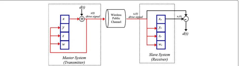
Contrary to a trigger-based slave/receiver chaotic syn-chronization by the transmitted chaotic masking signal, which limits the performance of the rate synchroniza-tion transmission [24], we propose a digital feedback hyperchaotic synchronization (FHS). More precisely, we investigate a new scheme for the secured transmission of information based on master-slave synchronization of hyperchaotic systems, using unknown input observers. The proposed digital communication system is based on the FHS through a dynamic feedback modulation (DFM) technique between two Lorenz hyperchaotic generators. The proposed FHS-DFM technique used for chaotic masking communications is depicted in Figure 1. This technique is an extension and improvement of the one developed in [35] for synchronizing two 3D continuous chaotic systems in the case of a wired connection. The proposed digital feedback communication scheme syn-chronizes the master/transmitter and the slave/receiver by the injection of the transmitted masking signal in the hyperchaotic dynamics of the slave/receiver. The basic idea of the FHS is to transmit a hyperchaotic drive sig-nalS(t)after additive masking with a hyperchaotic signal x(t)of the master (transmitter) system (x,y,z,w). Hyper-chaotic drive signal is then injected both in the three subsystems (y,z,w) and (yr, zr,wr). The subscriptr
rep-resents the slave or receiver system (xr,yr,zr, andwr). At
the receiver, the slave system regenerates the chaotic sig-nalxr(t) and a synchronization is obtained between two
trajectoriesx(t)andxr(t)if
lim
Figure 1HS-DFM principle scheme.This figure presents the hyperchaotic feedback synchronization via a dynamic feedback modulation (HS-DFM) technique.
This technique can be applied to chaotic modulation. In our case, it is used for generating hyperchaotic keys for stream cipher communications, where the synchro-nization between the encrypter and the decrypter is very important. Therefore, at the transmitter, the transmit-ted signal after the additive hyperchaos masking (digital modulation) is
S(t)=x(t)+d(t), (2)
where d(t) is the information signal and x(t) is the hyperchaotic carrier. At the receiver, after synchroniza-tion of the regenerated hyperchaotic signal xr(t) with
the received signalSr(t)and the demodulation operation,
we can recover the information signal d(t) correctly as follows:
d(t)=Sr(t)−xr(t). (3)
Therefore, the slave/receiver will generate a hyper-chaotic behavior identical to that of the master/ transmitter allowing to recover correctly the information signal after the demodulation operation. The advantage of this technique is that the information signald(t)does not perturb the hyperchaotic generator dynamics, con-trary to the ACM-based techniques of [10] and [36], because d(t) is injected at both the master/transmitter and slave/receiver after the additive hyperchaotic masking (Figure 1). Thus, for small values of information mag-nitude [35], the information will be recovered correctly. It should be noted that we have already confirmed this advantage by testing experimentally the HS-DFM tech-nique performances for synchronizing hyperchaotic sys-tems (four-dimensional (4D) continuous chaotic syssys-tems) in the case of wired connection between two Virtex-II Pro development platforms. After many experimental tests
and from the obtained real-time results, we concluded that the HS-DFM is very suitable for wired digital chaotic communication systems. However, in the present work, one of the objectives is to test and study the performances of the HS-DFM technique in the presence of channel noise through real-time wireless communication tests as it is shown in Figure 1. To perform the proposed approach, a digital implementation of the master and slave hyper-chaotic systems is required. Therefore, we investigate the hardware implementation of the proposed FHS-DFM technique between two Lorenz hyperchaotic generators using FPGA. To achieve this objective, we propose the following details of the proposed architecture.
FPGA implementation of hyperchaotic Lorenz generator
System model and numerical resolution
In general, autonomous continuous hyperchaotic systems are modeled by the following four non-linear differential equation systems:
˙
x=F(x,y,z,w),
˙
y=G(x,y,z,w),
˙
z=Q(x,y,z,w),
˙
w=P(x,y,z,w),
(4)
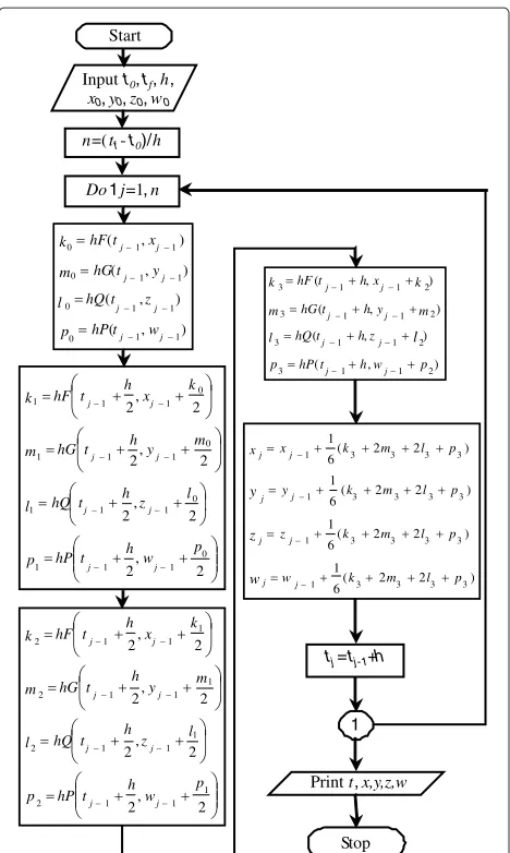
whereF,G,Q, andPare non-linear equations andx,y,z, andware the four state variables of the dynamical system. For computing the solutions of the system (4), we use the fourth order Runge-Kutta (RK-4) numerical method for resolving the continuous chaotic system models because it produces a more accurate estimate of the solution [27-29]. The flowchart of this method for resolving system (4) is illustrated in Figure 2, wherex0,y0,z0, andw0are the initial conditions,his the iteration step, andki,mi,li,
) ( ) ( ) ( ) ( 1 1 0 1 1 0 1 1 0 1 1 0 , , , , j j j j j j j j w t hP p t hQ l t hG m x t hF k z y 2 , 2 2 , 2 2 , 2 2 , 2 0 1 1 1 0 1 1 1 0 1 1 1 0 1 1 1 p w h t hP p l z h t hQ m y h t hG k x h t hF k j j j j j j j j l m 2 , 2 2 , 2 2 , 2 2 , 2 1 1 1 2 1 1 1 2 1 1 1 2 1 1 1 2 p w h t hP p l z h t hQ m y h t hG k x h t hF k j j j j j j j j l m ) , ( ) , ( ) , ( ) , ( 2 1 1 3 2 1 1 3 2 1 1 3 2 1 1 3 p w h t hP p z h t hQ l m y h t hG m k x h t hF k j j j j j j j j l ) 2 2 ( 6 1 ) 2 2 ( 6 1 ) 2 2 ( 6 1 ) 2 2 ( 6 1 3 3 3 3 1 3 3 3 3 1 3 3 3 3 1 3 3 3 3 1 p l m k w p l m k z p l m k y p l m k x x j j j j j j j j w z y Start
Inputt0,tf,h, x0,y0,z0,w0
n=(tf-t0)/h
Do1j=1,n
tj=tj -1+h
1
Printt,x,y,z,w
Stop
Figure 2Flowchart of the RK-4 method for resolving continuous hyperchaotic systems model.The flowchart describes the fourth order Runge-Kutta (RK-4) numerical method used for resolving the continuous chaotic system models, wherex0,y0,z0, andw0are the initial conditions,his the iteration step, andki,mi,li, andpi(i=0 to 3) are the intermediate slopes.
In this work, we are interested in the hyperchaotic Lorenz system modeled as follows [34]:
˙
x=a(y−x),
˙
y=x(b−z)−y+w,
˙
z=xy−cz,
˙ w= −fx.
(5)
In [34], it has been proven that this 4D lorenz system exhibits hyperchaotic behaviors and presents a two-dimensional bifurcation diagram for the following param-eter conditions : a = 10, c = 8/3, 0 < b < 30, and 0 < f < 15. Therefore, the system preserves its
-25 -20 -15 -10 -5 0 5 10 15 20
-40 -30 -20 -10 0 10 20 30 x y
Figure 3Matlab simulation result of the(x−y)hyperchaotic Lorenz attractor.
hyperchaotic behavior and bifurcation diagram for the
fol-lowing considered parameter values a = 10, b = 28,
c = 8/3, andf = 5 and with the initial conditionsx0 = y0=z0=w0= −10. The Matlab simulation result, using the presented RK-4 method, of the(x−y)hyperchaotic Lorenz attractor is given in Figure 3.
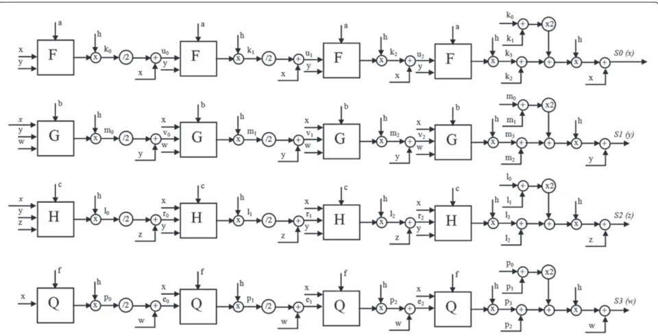
Hardware architecture
Figure 4Architecture of the hyperchaotic Lorenz generator module.The four outputsS0,S1,S2, andS3are the hyperchaotic signals, encoded on 32-bit (16Q16) fixed-point data format. The two inputs, clk and reset, are the clock signal and the reset signal, respectively.
inputs, clk and reset, which are the clock and reset signals, respectively. This data-path architecture is controlled by a specific finite-state machine in order that this struc-ture performs the RK-4 resolution method. Precisely, the developed hardware architecture is based on the Moore state machine (MSM) presented in Figure 5 where ten states (ST0 to ST9) are used.
The operating principle of the developed MSM (Figure 5) is as follows:
• ST0. In the initial state, all outputs are initialized to 0, and the state variables are initialized by the initial condition valuesx=x0,y=y0,z=z0, andw=w0. The process then passes unconditionally to the next state ST1.
• ST1. Compute the initial slopesk0,m0,l0, andp0, and the first intermediate pointsu1,v1,r1, ande1 defined by the following equations (see Figure 2):
u1=xj−1+k0/2 (6)
v1=yj−1+m0/2 (7)
r1=zj−1+l0/2 (8)
e1=wj−1+p0/2 (9)
At the next clock cycle, the machine passes unconditionally to the next state, ST2.
• ST2. Assign the values of the first intermediate points
u1,v1,r1, ande1to the variablesα,β,γ, andθ, respectively. The use of these variables permits to optimize our architecture. Indeed, we use the same
module to calculate all the slopes of the RK-4 method, and the same module is used for the calculation of the intermediate points. At the next clock cycle, the machine passes unconditionally to the next state, ST3. • ST3. Compute the slopesk1,m1,l1, andp1and the
second intermediate pointsu2,v2,r2, ande2.
u2=xj−1+k1/2 (10)
v2=yj−1+m1/2 (11)
r2=zj−1+l1/2 (12)
e2=wj−1+p1/2 (13)
At the next clock cycle, the machine passes unconditionally to the next state, ST4.
• ST4, ST6. Use the same instructions as stated in ST2;
update the variablesα,β,γ, andθ, and at the next clock cycle, the process passes unconditionally to the next state.
• ST5. Compute the slopesk2,m2,l2, andp2and the last intermediate pointsu3,v3,r3, ande3defined by the following equations:
u3=xj−1+k2 (14)
v3=yj−1+m2 (15)
Figure 5Moore state machine of the RK-4 hardware description. The Moore state machine (MSM) uses ten states (ST0 to ST9).
e3=wj−1+p2 (17)
At the next clock cycle, the process passes unconditionally to the following state.
• ST7. Compute the slopesk3,m3,l3, andp3and then
the solutionsx, y, z, and w (see Figure 2).
• ST8. Assign the hyperchaotic solution values x, y, z,
andw to the outputsS0,S1,S2, andS3, respectively. At the next clock cycle, the process passes
unconditionally to the final state, ST9.
• ST9. In the final state, the actual solution values x, y,
z, and w are assigned to the variablesα,β,γ, andθ, respectively, to compute the next hyperchaotic solution values. At the next clock cycle, if the counter
value, cp, is equal to a defined integer valueN, the
process goes back again to the first state, ST1, and then the process is revived again for calculating the next solution values. Otherwise, the process stays
waiting at state ST9. The value ofN is chosen to
ensure synchronization between the embedded hyperchaotic generator and an external connected device, permitting the control of the throughput of the embedded hyperchaotic generator.
Synthesis results and performance analysis
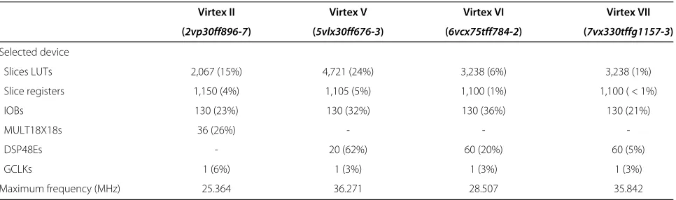
The synthesis results after the place and route of the implemented architecture on the Xilinx Virtex-II (Pro XC2VP30), Virtex V, VI, and VII FPGAs [32,37-39] are detailed in Table 1. Herein, the maximum frequency and the hardware resource’s consumption in terms of slices, digital signal processing (DSP) blocks and multipliers required are specified. The results demonstrate that the proposed hyperchaotic Lorenz generator can be easy and efficiently implemented on FPGA technologies by provid-ing real-time hyperchaotic signals and attractors. It can be stated that an attractive tradeoff between high speed and low logic resources is achieved. Indeed, our imple-mentation on a Xilinx Virtex-II Pro device uses only 2067 CLB-Slices (15% of the size circuit), 36 multipliers (26%) and no block RAMs is used under the maximum fre-quency of 25.364 MHz. Similarly, our implementation on a Xilinx Virtex V device uses 4721 CLB-Slices, 20 DSP blocks under the maximum frequency of 36.271 MHz. We note that the use of DSP blocks with most recent devices improves the performance.
To evaluate the performance of the proposed hard-ware implementation, the throughput rate and time latency metrics are used. In our case, the throughput rate (defined as the number of bits per unit of time)
Table 1 Synthesis results
Virtex II Virtex V Virtex VI Virtex VII
(2vp30ff896-7) (5vlx30ff676-3) (6vcx75tff784-2) (7vx330tffg1157-3)
Selected device
Slices LUTs 2,067 (15%) 4,721 (24%) 3,238 (6%) 3,238 (1%)
Slice registers 1,150 (4%) 1,105 (5%) 1,100 (1%) 1,100 ( < 1%)
IOBs 130 (23%) 130 (32%) 130 (36%) 130 (21%)
MULT18X18s 36 (26%) - -
-DSP48Es - 20 (62%) 60 (20%) 60 (5%)
GCLKs 1 (6%) 1 (3%) 1 (3%) 1 (3%)
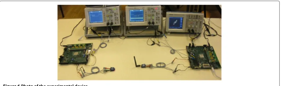
Figure 6Photo of the experimental device.
corresponds to 32 bits of wordlength for ten operating clock cycles (for number of MSM states, see Figure 5) after the initialization phase at the output of the FPGA circuit.
Latency is defined as the time required to generate one single wordlength signal after the start of the generator. Therefore, a minimum and maximum throughput of 81.16 and 116 Mbps with a maximum and minimum time latency of 394.25 and 275.7 ns are obtained for Virtex II and Virtex V technologies, respectively. The results prove that our hardware architecture can be implemented in the recent FPGA devices with a significant ameliora-tion of its performances in terms of throughput and logic area cost.
Experimental framework
To test and validate the proposed approach, we have real-ized the experimental framework depicted in Figure 6. For this purpose, we consider the available XUP Xilinx Virtex-II Pro development embedded platforms for phys-ical hardware implementations [32]. The XUP System consists of a high-performance Virtex-II Pro FPGA (XCV2PFF896-7) surrounded by peripheral components that can be used to create a complex hardware system. Note that an audio CODEC (AC97) and stereo power amplifier are included on the XUP platform so as to pro-vide complete analog functionality, allowing the external generation of chaotic signals in analog form for real mea-surements [40]. Both the transmitter and the receiver are mounted on a Virtex-II Pro Development System [32] connected to an XBee module based on Zigbee or Wi-Fi communication protocols [26,33]. The experimental transmission test consists of transmitting a binary infor-mation data, encoded on a 32-bit fixed-point data format, and masked (secured) by the master hyperchaotic sam-ples (Figure 1), encoded also on a 32-bit fixed-point data format. At the receiver, we verify, after the demodulation operation (unmasking), the correct recovery of the trans-mitted data information. To view the result on a digital
oscilloscope, a constant value is used as information data to test the feasibility of the proposed wireless commu-nication system based on the association of the hyper-chaotic communication with the ZigBee communication technology.
XBee RF modules
XBee modules offer the advantage to interface to a host device through a well-known logic-level asynchronous serial port. In fact, devices having a UART interface can connect directly to the pins of the RF modules [26,33]. In our experiment, we use the XBee modules in their trans-parent mode with the minimum connections VCC, GND, Tx, andRxas showed in Figure 7. When operating in this
mode, the modules act as a serial line replacement, i.e., all UART data, consisting of a start bit (low), eight data bits (least significant bit first), and a stop bit (high), received through theRxpin queued up for RF transmission. When
RF data is received, the data is sent out theTxpin.
Transmitter architecture
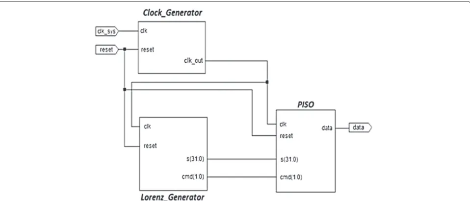
The transmitter architecture implemented on the first FPGA circuit is presented in Figure 8. It is com-posed mainly of three modules : Clock_Generator, Lorenz_Generator, and parallel input/serial output (PISO). The details of the functioning of each module are as follows :
Figure 8Transmitter architecture.The transmitter architecture is composed mainly of three modules: Clock_Generator, Lorenz_Generator, and the parallel input/serial output (PISO) modules.
- Clock_Generator. This module generates and
provides the clock (clk_out) and reset signals to the two other modules. The frequency of the clock signal is imposed either by the serial interface data rate of the XBee modules (see Table 2) or the implemented logic blocks in the FPGA. Depending on the maximum data rate allowed, the clk_out signal frequency is defined for driving the transmitter architecture. To obtain this frequency, we have implemented a clock divider architecture to derive it from the frequency of the 100 MHz global clock signal (clk_sys) provide by the Xilinx Virtex-II Pro XC2VP30 FPGA.
- Lorenz_Generator. This module represents the main
module of the proposed transmitter architecture. It is based on the hardware architecture already detailed and presented in the ‘FPGA implementation of hyperchaotic Lorenz generator’ section for implementing the hyperchaotic Lorenz system but with some modifications introduced in the MSM of Figure 5 in order to adapt with the hyperchaotic
generator data outputS to the XBee module data
inputRx. The adaptation includes introducing a 2-bit
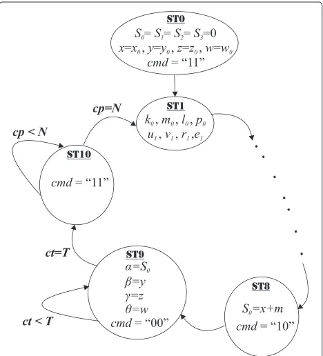
control signal (cmd) in the hyperchaotic generator architecture which will control the operation of the parallel/serial converter module (PISO) to provide data frames according to the XBee communication protocols (Zigbee or Wi-Fi) [26,33]. Therefore, the changes in the Lorenz_Generator architecture are as follows :
At the initial state ST0, we set cmd = ‘11’, and the process follows the same steps as in the ‘FPGA implementation of hyperchaotic Lorenz generator’ section until reaching state ST7. However, to realize our solution, we have added an 11th state to the MSM, and then from the state ST8, the next steps are as follows:
• ST8. We realize the modulation operation using
additive chaos masking of [10] and [36], i.e., the
information signal samplesd are masked by
those of the hyperchaotic signalx and then the
Table 2 Wireless performance and data or image transmission results
Protocol Zigbee (WPAN) Wi-Fi (WLAN)
Maximum distance (indoor/urban range) Up to 100 ft (30 m) Up to 120 ft (32 m)
Transmit power output of Xbee modules 1 mW (0 dBm) >15 dBm
Maximum data bit rate (modulation rate) 250 Kbps (6,250 baud) 25.364 Mbps (634,100 baud)
Maximum RF data rate 250 Kbps 54 Mbps
Supply voltage 2.8 to 3.4 V 3.1 to 3.6 V
Operating frequency modulation ISM 2.4 GHz ISM 2.4 to 2.5 GHz
hyperchaotic samplex. We put cmd =‘00’, and the passage to the next state, ST10, is controlled
by the parameter valueT of the counter ct.
More details are given in the next paragraph.
• ST10. This tenth state is added to control the
eventual distance between two successive data frames which can imposed by the XBee communication protocols [26,33]. This is
ensured by the parameter valueN of the
counter cp as shown in Figure 9. In this last state, cmd is set to the value 11.
- PISO. This module is a binary parallel/serial
converter. Under the command signal cmd, the
module converts the parallel data samplesS0(coded
in 32 bits), received from the Lorenz_Generator module after the modulation operation, to a serial data. The command signal values are presented in Table 3. The transmitted data frame is formed by four
Figure 9Lorenz_Generator state machine at the transmitter.
Therefore, the data frame wordlength isT =40bits.
Note that this data format is imposed by the XBee RF module’s communication protocols [26,33].
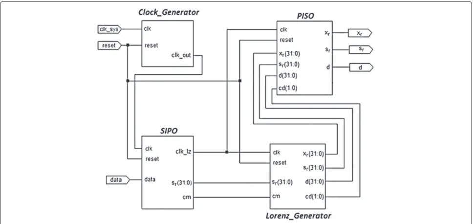
Receiver architecture
The receiver architecture is presented in Figure 10. It is composed of four modules : Clock_Generator, Lorenz_Generator, PISO, and serial input/parallel output (SIPO). The first three modules are similar to those of the transmitter but with an adjustment to the receiver. The details of the functioning of each module are as follows:
- SIPO. This module is a binary serial-to-parallel
converter. Once the start bit is detected at the receiver by the SIPO module, the serial/parallel conversion of the received data begins. At the same time, the module generates a clock signal (clk_lz) at the same frequency as the clk_out clock signal generated by the Clock_Generator module. This means that the generation of the clk_lz clock signal is triggered at each start bit detection. This constitutes our interesting solution to overcome the problem of shifting data frames at the XBee RF module output
(Tx). Indeed, this solution permits to adapt and to
synchronize the execution of the implemented receiver architecture to the cadence of the XBee RF
module data output (Tx). However, to synchronize
the SIPO and the Lorenz_Generator modules, we use a 1-bit command signal (cm). Initially, this last one is set to ‘0’, and it is set to ‘1’ during one clock period
only when the converted 32-bit parallel dataSrare
available at the output of the SIPO module, i.e., the serial-to-parallel conversion is finished.
- Lorenz_Generator. This module is similar to the
Figure 10Receiver architecture.
synchronizes them with the received and parallel
converted data samplesSrand recovers the
information datad after a demodulation operation
based on the arithmetic subtraction. Finally, it controls the parallel-to-serial conversion operation of the PISO module using the 2-bit command signal cd. The cd commands are the same as those of cmd command signal presented in Table 3. As the transmitter architecture, the Lorenz_Generator module uses the same state machine presented in Figure 5, but with the modifications introduced and presented in Figure 11.
At the first clk_lz clock cycle, the module starts the execution of the state machine instructions from ST0 to ST7. Therefore,
• At the synchronization step ST8, we assign the
generated hyperchaotic samplesx to the output
xrand the received and parallel converted data
Srto the outputSr(Figure 11). Note that we
have used the same parameter nameSrfor the
parallel converted data at the input and the output of the Lorenz_Generator module because no change is made for this data at this module. Therefore, if the command signal cm is set to 1, i.e., the received dataSrare available at the output of the SIPO module, then the process passes to the next state, ST9. Otherwise, it stays waiting at the current state.
• At the demodulation step ST9, after the
synchronization of thexrandSrsamples at the
hyperchaotic synchronization principle presented in Figure 6, in which the received signalS(t)is injected to the dynamic of the hyperchaotic generator of the receiver. Finally,
afterN clock cycles, the process passes to state
ST1. The value ofN is fixed by the time needed
by the PISO module to finish the
parallel-to-serial conversion of the hyperchaotic
samplesxr. Then, in our experiments,N = 33
clock cycles, considering that the samplesxrare
encoded on 32 bits.
- PISO. This module is similar to that in the
transmitter block. Under the command signal cd, it converts the 32-bit parallel outputs of the
Lorenz_Generator module, i.e., the regenerated
hyperchaotic samplesxr, the received data samples
Sr, and the recovered data informationd, to 32-bit
serial frames. This module is introduced in the architecture just for validating the proposed approach by real-time viewing and comparing these serial data frames on a digital oscilloscope.
Wireless real-time data or image transmission tests and results
The main considered application is the security of wire-less sensor networks (WSNs) which are becoming more and more important, and they can gain advantage of reconfigurable technology, in terms of flexibility, energy consumption, and sensor lifetime. This is particularly true for the networks of data diffusion based on embedded sys-tems, which can be used for the protocol communication. Indeed, a WSN provides different aspects in the sharing of information by deploying a system that is able to execute wireless exchange of data, image, or video [41] according to transmission rate performance. Subsequently, we con-sidered the wireless data or image transmission with the Zigbee and WiFi protocols in a WSN context.
The ciphered data or image is transmitted through a public and unsecure channel. Using self-synchronization technique at the receiver side [32], the key can be recov-ered at the receiver and the decryption operation from the transmitted scrambled image with the regenerated key, allowing us to recover the plain image.
associated XBee Pro RF module transmits the received data to the SIPO module according to the asynchronous serial communication protocol to regenerate the received encrypted signal sample format Sr(t), allowing for the
hyperchaotic synchronization and recovery of the masked informationd(t)according the proposed scheme depicted in Figure 1.
Table 2 summarizes experimentally the performance and results in terms of digital transmission rate (symbol rate or modulation rate), maximum distance, and fre-quency modulation according to the considered wireless protocols by the Xbee RF modules and Virtex II technol-ogy. For these measurements, we have placed the trans-mitter and the receiver at two neighboring rooms at the distance about 20 m with a received signal strength indi-cator (RSSI) of−2 dBm. With this disposition, we obtain a packet error rate (PER) of 0% at the receiver. The maxi-mum distance that we can obtain experimentally between the transmitter and the receiver (indoor range) is more than 30 and 32 m for Zigbee and Wi-Fi protocols, respec-tively. Therefore, the indoor/urban ranges of the XBee RF modules used are up to 30 m (see Table 2), and the sensi-tivity of the XBee RF module receivers reaches−92 dBm with a PER of 1% [33]. The XBee modules offer the advantage to realize a wireless communication applica-tion without errors (PER = 0%) according to environment application, distance, disposition, and channel chosen as is shown in [42].
Xbee RF modules while FPGA implementations allow to provide transmission rates to at least 25 Mbps. Thereby, for a null distance frame value (N =0), the obtained data bit rate of the serial communication is 250 kbps (corre-sponding to a modulation rate of 625 symbols per second or baud, due to the maximum serial interface data rate of the Zigbee protocol based XBee Pro modules [33], and with an operating frequency modulation of 2.4 GHz. In the case of the Wi-Fi protocol, the maximum bit rate of the proposed system is limited by the work frequency of the implemented hardware modules. Although the FPGA implementation of the Lorenz generator allows to provide a throughput of 80 Mbps (maximal frequency of 25 MHz is allowed by the considered Virtex II platform with an encoded 32-bit encrypted data), the maximum transmis-sion bit rate of the proposed system is limited by the
hyperchaotic key generators up to 25 Mbps (forN = 0)
and by a corresponding modulation rate of 625,000 baud.
Therefore, the parallel/serial and serial/parallel convert-ers to Wi-Fi Xbee RF modules limit the transmission rate up to the maximum work frequency, depending on the considered FPGA technology. Indeed, each symbol of the data transmission system carries 40 bits according to the data frame wordlength allowed by the serial inter-face Xbee modules. This digital modulation rate oper-ates with a frequency modulation range between 2.4 and 2.5 GHz [26]. In summary, considering a synchronous sys-tem at the maximum work frequency allowed between the key stream generators and parallel/serial or serial/parallel converters, the limitations with respect to 54-Mbps and 25-kbps bit rates of the Wi-Fi and Zigbee RF modules are due to the work frequencies of hyperchaotic Lorenz generators and the serial interface data rate, respectively.
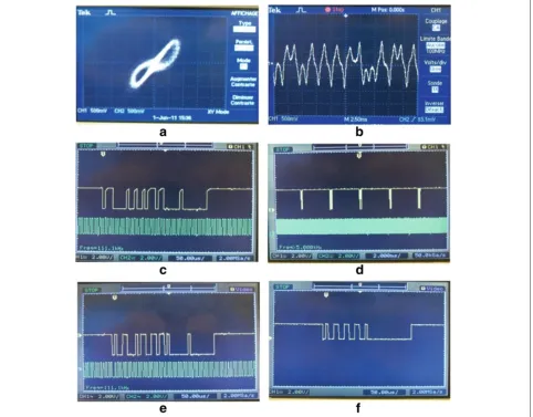
An example of real-time data results obtained for a constant value of ‘00009999’ is shown in Figures 12 and 13. These figures give snapshots of the real-time
nalx, respectively. An example of the transmitted serial masked data frames with the corresponding clock signal is presented in Figure 12c. Figure 12d shows the dis-tance between the transmitted data frames, and Figure 12e presents an example of the received data frame at the output of the XBee module of the receiver with the corresponding clock signal clk_lz. Finally, the recovered information data (only for the constant value 00009999) is shown in Figure 12f. Note that the transmitted masked data frame presented in Figure 12c shows the robust-ness security of the information data, in the proposed wireless communication system, by the additive hyper-chaos masking principle. In fact, the information data are totally hidden by the hyperchaotic ones. The results of Figure 12e validate our proposed solution for adapting and synchronizing the implemented receiver architecture and the XBee RF module. Indeed, from the results, we note that the clock signal clk_lz is triggered at the start bit detection of the received data frame. Finally, the results presented in Figure 12f validate the principle of the pro-posed wireless hyperchaotic communication system and then the relevant idea based on associating the hyperchaos communication principle with the ZigBee technology. In fact, from this figure, we see that the information data are recovered correctly without any error at a distance of 20 m
because PER=0%.
In Figure 13, we present the first three successive recov-ered information data frames for an RSSI of−70 dBm and a PER of about 1%. These results show that the informa-tion data are totally lost because of the PER of 1%. This confirms the extreme sensibility of chaotic synchroniza-tion to small channel perturbasynchroniza-tion.
For secure real-time video transmission in the WSN, we consider an encrypted video transmission rate of 25 images per second with a spatial resolution of 128x128 gray level pixels coded at 8 bits. Each pixel value is extended to 40 bits according to the wordlength data frame format of the encryption process and serial transmission [26,33]. Consequently, we deduce a time constraint of 40 ms by image to assure that the real-time wireless transmission rate corresponds to a minimum bit rate of 16,384 kbps or modulation rate of 409,600 baud. Therefore, the proposed system based on Wi-Fi XBee modules, which can be performed up to the maximum
Figure 13Oscilloscope snapshots of three successive recovered information data frames for RSSI =−70 dBm and PER≈1%(a, b, c).The experimental measurements of the data frames have been done by a digital oscillocope with a timebase of 50μs, a sensibility of 2 Volts-per-Division and a sample rate /channel of 2 MegaSAmples per second (MSA/s).
Figure 14Snapshot of a wireless real-time image transmission based on the Wi-Fi protocol.
Security analysis
To test the robustness of the proposed scheme, secu-rity analysis including statistical analysis and differential analysis was performed. This evaluation of the qual-ity of randomness is carried out to demonstrate the satisfactory security of the new proposed chaos-based cryptosystem.
NIST statistical analysis
A large number of statistical tests and whole test suites have been proposed to assess the statistical properties of random number generations. Statistical tests of the generated 128-bit encryption keys are commonly per-formed using the standard NIST SP 800-22 statistical test suite [43]. In this subsection, we present the per-formance test results of the proposed chaos-based key stream generator. Eighteen statistical tests are commonly used to determine whether one binary sequence pos-sesses some specific characteristics that a truly random sequence would be likely to exhibit. Table 4 summa-rizes the results of NIST tests. Each one was performed 300 times on 1-Mbit substrings. A single test is con-sidered as passed if the P value is above the signifi-cant level of 0.01 or below 0.99 [43]. The results of
Table 4 show the measured values ofP value T,
know-ing that if P value T ≥ 0.0001, then the sequences
can be considered to be uniformly distributed. Simi-larly, the minimum pass rate for each statistical test with the exception of the random excursion (variant) test is approximately 0.972766 for a sample size equal to 300 binary sequences (for more details, see the refer-ence [43]). Figure 15 gives the Matlab simulation result of the (x−y−z) phase space and confirms these sta-tistical results. Indeed, this phase space is occupied by random trajectories proving that the sequences are really uniformly distributed. Consequently, we can conclude that the proposed chaos-based key stream generator suc-cessfully passes all the NIST tests and provides good
randomness keys. Therefore, these results demonstrate that the proposed chaos-based key stream is very useful for the consideration of reducing negative dynamic degra-dation influence due to the finite precision of the digital hardware implementation.
Histogram and differential analysis
To demonstrate the effectiveness of confusion and dif-fusion proprieties, a histogram test is carried out and shown. Since an image histogram illustrates how pix-els in an image are distributed by plotting the number
Table 4 NIST tests results
Statistical tests PvalueT Proportion
Frequency 0.644060 0.9800
Block frequency 0.023545 0.9833
Cumulative sum up 0.671779 0.9900
Cumulative sum down 0.699313 0.9933
Runs 0.117661 0.9933
Longest run 0.630178 0.9967
Rank 0.840081 0.9867
Discrete Fourier transform 0.100508 1.0000 Non-overlapping templates 0.588652 0.9833
Overlapping templates 0.547637 1.0000
Universal 0.568055 0.9833
Approximate entropy 0.162606 0.9933
Random excursions 0.249991 0.9947
Random excursion variant 0.711827 0.9840
Serial 1 0.706149 0.9833
Serial 2 0.110952 0.9833
Lempel-Ziv value 0.071177 0.9900
Linear complexity 0.487885 0.9967
Figure 15Matlab simulation result of (x−y−z) phase space showing that encryption key sequences are really uniformly distributed.
of pixels at each gray-scale intensity level. By select-ing several 256 gray-scale images with a resolution of 256x256 with different image contents, their his-tograms were calculated. The typical example (camera-men image) among them is shown in Figure 16. The obtained histogram of the ciphered image is fairly uni-form and significantly different from that of the orig-inal image showing then the sensitivity to the plain image.
To avoid the known-plaintext attack and the chosen-plaintext attack, the changes in the ciphered image should be significant even with a small change in the original one. According to the proposed encryption process, this small difference should be diffused to the whole ciphered data, with respect to diffusion and confusion. Consequently, this differential attack would become very inefficient and practically useless. Generally, the differential analysis can be reflected by the number of pixels’ change rate (NPCR) and unified average changing intensity (UACI) evaluations [44]. NPCR stands for the number of pixels’ change rate while one pixel of plain image changed. The more NPCR gets close to 100%, the more sensitive the cryptosystem to the changing of plain image is and then the more effec-tive for the cryptosystem to resist plaintext attack. UACI measures the average intensity of differences between two encrypted images. Currently, the bigger the UACI, the more effective is the cryptosystem to resist at a differential attack.
The plain cameraman image is used in the test. The first image is the original plain image, and the second is obtained by changing the first pixel gray-scale value (for the cameraman image, the change was from ’28’ to ’29’). Therefore, the two images are encrypted with the same key to generate the corresponding cipher images C1 and C2 (encrypted images before and after one pixel of the plain image is changed). We obtain the results by
simulating experiments which are shown in Table 5. We can find that the NPCR and the UACI are over 99% and 33%, respectively. These results show that the proposed encrypted algorithm is very sensitive to tiny changes in the plain image, even if there is only one different bit between the two plain images. Consequently, the decrypted images will be strongly different, showing the robustness of the proposed encryption scheme against one differential attack.
In summary, this security analysis proves that encrypted and synchronized generated signal is non-periodic and has a flat spectrum which is suitable for encryption image scheme by showing a robustness against plaintext attacks.
Conclusions
Figure 16Test of the distribution (histogram) between adjacent pixels in a ciphered image.
in the proposed FPGA transmitter side and the slave chaotic system is embedded in the FPGA receiver side. Many real-time transmission tests are carried out between two distanced Virtex II-Pro Xilinx FPGA platforms. The obtained real-time results show the efficiency of the pro-posed idea consisting on associating the hyperchaotic communication, and the ZigBee or Wi-Fi communica-tion protocols characterized by high immunity against channel noise. Indeed, we could recover correctly the information data on the distance about 20 m using the
XBee RF modules at −2 dBm with a PER of 0%. Note
that these performances can be improved using the most recent XBee modules. Experimental results applied to image encryption have demonstrated that our approach exhibits attractive performances and is useful in the field of real-time secure wireless data communications. The proposed technique may make it more applicable in such field (video, image, internet, etc.) and for all
type of wireless network. Indeed, thorough experimen-tal tests have been carried out with detailed numeri-cal analysis, demonstrating the high security of the new data or image encryption scheme. More precisely, the proposed approach used to design a secure symmet-ric image encryption increases its resistance to various attacks such as statistical and key analysis attacks and can avoid the hidden security attacks in real-time applications. Finally, our perspective for the presented work consists on developing and realizing a secure wireless hyperchaotic communication network using the proposed modulation system.
Table 5 Results of NPCR and UACI tests
Plain image NPCR (%) UACI (%)
scheme for the security of networked, real-time video, inProceedings of the 4th International Conference on Computer Communications and Networks, Las Vegas, 20-23 Sept 1995(IEEE, Piscataway, 1995), pp. 2–10 2. T Yang, A survey of chaotic secure communication systems. Int. J.
Comput. Cogn.2(2), 81–130 (2004)
3. B Schneier,Applied Cryptography: Protocols, Algorithms, and Source Code in C, 2nd edn (Wiley & Sons, New York, 1996)
4. J Zambreno, D Nguyen, AN Choudhary, Exploring area/delay tradeoffs in an AES FPGA implementation, inField Programmable Logic and Applications,ed. by J Becker, M Platzner, S Vernalde. Proceedings of the 14th International Conference, FPL 2004, Leuven, 30 August-1 September 2004. Lecture Notes in Computer Science, vol. 3203.
(Springer, Heidelberg, 2004), pp. 575–585
5. X Yi, CH Tan, K SC, MR Syed, Fast encryption for multimedia. IEEE Trans. Consum. Electron.47(1), 101–107 (2001)
6. MP Kennedy, G Kolumban, Digital communication using chaos. Signal Process.80, 1307–1320 (2000)
7. G Alvarez, S Li, Some basic cryptographic requirements for chaos-based cryptosystems. Int. J. Bifurcation Chaos.44, 2129–2151 (2006) 8. JS Lin, TL Liao, CF Huang, J Yan, Design and implementation of digital
secure communication based on synchronized chaotic systems. Digit. Signal Process.20, 229–237 (2010)
9. W Chang, Digital secure communication via chaotic systems. Digit. Signal Process.19, 693–699 (2008)
10. KM Cuomo, AV Oppenheim, SHS Trogatz, Synchronization of
Lorenz-based chaotic circuits with applications to communications. IEEE Trans. Circuits Syst. II: Analog Digit. Signal Process.40(10), 626–633 (1993) 11. H Dedieu, MP Kennedy, M Hasler, Chaos shift keying: modulation and
demodulation of a chaotic carrier using self-synchronizing Chua’s circuits. IEEE Trans. Circuits Syst. II: (Special Issue on Chaos in Nonlinear Electronic Circuits- Part C: Applications).40, 634–642 (1993)
12. KS Halle, WC Wah, M Itoh, LO Chua, Spread spectrum communication through modulation of chaos. Int. J. Bifurcation Chaos.3, 469–477 (1993) 13. S Hayes, C Grebogi, E Ott, Communicating with chaos. Phys. Rev. Lett.
70, 3031–3034 (1993)
14. YC Lai, E Bollt, C Grebogi, Communicating with chaos using two-dimensional symbolic dynamics. Phys. Lett. A.255, 75–81 (1999) 15. U Feldmann, M Hasler, W Schwarz, Communication by chaotic signals: the
inverse system approach. Int. J. Circuit Theory Appl.24, 551–579 (1996) 16. T Yang, A survey of chaotic secure communication systems. Int. J.
Comput. Cogn.2(2), 81–130 (2004)
17. I Grosu, E Padmanaban, PK Roy, SK Dana, Designing coupling for synchronization and amplification of chaos. Phy. Rev. Lett. 100, 234102 (2008)
18. M Eisencraft, AM Batista, Discrete-time chaotic systems synchronization performance under additive noise. IEEE Trans. Circuits Syst. II: Analog Digit. Signal Process.91, 2127–2131 (2011)
19. J Schweizer, T Schimming, Symbolic dynamics for processing chaotic signals-I: noise reduction of chaotic sequences. IEEE Trans. Circuits Syst. I. 48, 1269–1282 (2001)
20. M Ciftci, DB Williams, Optimal estimation sequential channel equalization algorithms for chaotic communications systems. EURASIP J. Appl. Signal Process.4, 249–256 (2001)
21. X Wang, Z Wang, A robust demodulation application communication using chaotic signals. Int. J. Bifurcation Chaos.13, 227–231 (2003) 22. K Murali, Heterogeneous chaotic systems based cryptography.
Phys. Lett. A.272, 184–192 (2000)
FPGA implementation of Lü’s chaotic generator for cipher embedded system. International Symposium on Signals, Circuits and Systems (ISSCS), Iasi, 9-10 July 2009 (IEEE, Piscataway, 2009), pp. 1–4
29. S Sadoudi, MS Azzaz, M Djeddou, M Bensalah, An FPGA real-time implementation of the Chen’s chaotic system for chaotic communications. Int. J. Nonlinear Sci.7(4), 467–474 (2009) 30. MI Sobhy, MA Aseeri, AER Shehata, Real time implementation of
continuous (Chua and Lorenz) chaotic generator models using digital hardware, inProceedings of the Third International Symposium on Communication System Networks and Digital Processing (CSNDSP), Staffordshire, 15-17 July 2002 (IEEE, Piscataway, 2002), pp. 38–41 31. LS Indrusiak, ECDS Junior, M Glesner, Advantages of the Linz-Sprott weak
nonlinearity on the FPGA implementation of chaotic systems: a comparative analysis. Proceedings of the Int. Symp. Signals, Circuits and Sys.2, 753–756 (2005)
32. Xilinx Inc.,Xilinx University Program Virtex-II Pro Development System, UG69 (v1.1)(Xilinx Inc., San Jose, 2008)
33. Digi International Inc,Product Manual v1.xEx - 802.15.4 Protocol (Digi International Inc., Minnetonka, 2009)
34. R Barboza, Dynamics of a hyperchaotic Lorenz system. Int. J. Bifurcation Chaos.17(12), 4285–4294 (2007)
35. V Milanovic, ME Zaghloul, Improved masking algorithm for chaotic communications systems. Elec. Lett.32, 11–12 (1996)
36. KML Kocarev, KS Halle, K Eckert, LO Chua, Experimental demonstration of secure communications via chaotic synchronization. Int. J. Bifurcation Chaos.2, 709–713 (1992)
37. Xilinx Inc,Virtex 5 FPGAs datasheet(Xilinx Inc., San Jose, 2008) 38. Xilinx Inc,Virtex 6 series fpgas configurable logic block
(Xilinx Inc., San Jose, 2012)
39. Xilinx Inc,Virtex 7 FPGAs datasheet(Xilinx Inc., San Jose, 2013) 40. Analog Devices,AC’97 SoundMAX Codec, AD1881A datasheet
(Analog Devices, Norwood, 2000)
41. J Yick, B Mukherjee, D Ghosal, Wireless sensor network survey. Comput. Netw.52(12), 2292–2330 (2008)
42. A Centeno, N Alford, Measurement of ZigBee wireless communications in mode-stirred and mode-tuned reverberation chamber. Prog.
Electromagnetics Res. M.18, 171–178 (2011)
43. A Rukhin, J Soto, J Nechvatal, M Smid, E Barker, S Leigh, M Levenson, M Vangel, D Banks, A Heckert, J Dray, S Vo, A statistical test suite for random and pseudorandom number generators for cryptographic applications. Technical report, NIST Spec. Publication 800-22 Revision 1a, NIST, Gaithersburg, 2010
44. Y Wu, J Noonan, S Agaian, NPCR and UACI randomness tests for image encryption. Cyber Journals: Multidisciplinary Journals in Science and Technology. J. Selected Areas Telecommunications.1(4), April 2011 Edition, 31–38 (2011)
doi:10.1186/1687-5281-2013-43
Cite this article as:Sadoudiet al.:Design and FPGA implementation of a
wireless hyperchaotic communication system for secure real-time image