77
Theoretical Analysis of Tunable
Single-Core Comb Filter Based on
MZI
J. N. Sikta*, M.S. Islam, N. N. Ripa
Department of physics, Jahangirnagar University, Savar, Dhaka-1342, Bangladesh
*Corresponding email: [email protected]
Abstract
In this work, a theoretical analysis of single core tunable comb filter based on Mach-Zehnder (M-Z) interferometer is proposed and demonstrated. The proposed filter consists of one QWP, one HWP, one SMF and onePMF segment consists of two PMF lengths. Depending on the dynamic settings of wavelength of the input signal, refractive index and length of the fiber material, the comb filter provides the channel spacing tenability, and peak wavelength position switchability. The proposed comb filter is polarization insensitive as PMF is used.
78 1. INTRODUCTION
Over the past few years, the ability to communicate and exchange information efficiently has a great contribution to the progress of human civilization. Recently, the rapid increase in the demand for an optical communication system has led to great interest in development of novel devices for the wavelength-division-multiplexed optical networks [1]. Periodic optical filters as a key component are widely used in multiwavelength fiber lasers [2- 4]. Multiwavelength-periodic section could be achieved by inserting a polarization-maintaining fiber (PMF) in the Sagnac fiber loop [5-6]. But waveguide-based MZI as a comb-like filter may be a better choice because of its inherent advantages [7], such as high reliability, insensitivity to environmental change, broad wavelength operation range [8-10]. The demultiplexing technique is the unique property that makes it special from other filters. This technique is very useful in WDM system. A novel tunable all-fiber comb filter based on modified dual-pass Mach-Zehnder(M-Z) interometer has been proposed already[1]. Although MZI is always believed as a non tunable optical filter except incorporating an optical variable delay line to change the path difference [11]. However, this increases the overall cost. Recently polarization independent tunable all-fiber comb filter based on a modified dual-pass MZI has been reported [12]. But this comb filter can be tuned for two fixed spectral spacing. Still it is far behind from continuous tunability of the spectral spacing, simplicity of maintaining polarization. In this research, the design for tunable single-core comb filter based on MZI has been proposed and investigated theoretically. In a comparison, the insertion loss in single-core fiber MZI tunable comb filter is very low and the extinction ratio is high as compared to the double-pass MZI. But its spectral spacing is higher than the double pass MZI configuration for the same length of the PMF segment. These types of filter are very simple in design and expected to have more efficient and flexible functionality
2. METHODOLOGY
The theoretical model of the proposed single-core tunable optical comb filter is developed based on the schematic diagram as shown in Figure 1. The structure consists of one QWP, one HWP, one SMF, and two PMF segments. Two PMF segments are considered to splice together in between two SMF segments. The splicing points are shown by a cross symbol in the figure. Schematic diagram of our proposed single-core tunable optical comb filter is as follows:
Figure 1: Schematic of proposed single-core tunable optical comb filter.
Laser input
SMF
PMF1
QWP HWP
PMF2
SMF
79
When light enters through the SMF it splits into two parts inside the PMF. One is along slow axis and another is along fast axis. Due to the path difference between slow and fast axis, there is a discrete path difference between two parts of the signal. This path difference can be controlled with the rotation of QWP. HWP is usually used to change the effective length of the PMF segment from maximum to minimum. But for the simplicity of the calculation HWP is considered fixed at 900 and here QWP is kept fixed at 450. When these two parts of signal enter into the SMF again interference occurs. As a result of interference, sinusoidal transmission output is supposed to be expected. The spectral spacing of the output depends on length, refractive index of the fiber material and the wavelength of the input signal. Peak wavelength position of the output transmission also depends on these factors.
Jones matrix for linear polarized light at an arbitrary angle α with the X-axis is
Sin Cos E (1) QWP with fast axis vertical is given by;
) 4 sin 4 (cos 0 0 ) 4 sin 4 (cos i i i QWP (2)
HWP with fast axis vertical is given by;
) 2 sin 2 (cos 0 0 ) 2 sin 2 (cos i i i HWP (3)
The matrices of the two interferometer arms,
Fn (n1,2)are
jknL jkn L
y x e e F 0 0 1 (4)
( ( ) 2 0 0 L kn j L kn j y x e e F (5)Where, φ is the phase difference due to path difference between two interometer arms. P is the polarization element of the fiber and is expressed as,
80
For the proposed comb filter, we can write the expression,
F1 P QWP
HWP
F2E E
in out
Using above equations we have,
) cos(
) cos(
cos cos
2
1
kn L kn L knL kn L
E E
y x
y x
in out
Now, transmission,
2
in out E E T
`
) cos(
) cos(
cos cos
2
1
knxL knyL knxL knyL 2 (7)
When, 90, equation (7) gives,
Sin A
T 2
32
1 2
2
;when
, n n nx y
we have,
knl B
A
(8) When, 45or 0, equation (7) gives,
) ( cos 2
1 8
knl
T when nx ny n(9)
Transmission spectra are obtained using equations (8) and (9). Different transmission spectrum for the values of different parameters are given below.
3. RESULTS AND DISCUSSIONS
3.1 Transmission
81
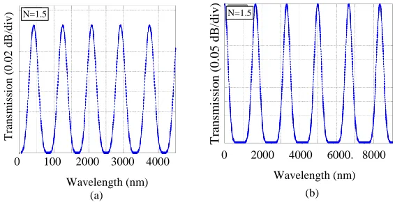
Figure 2: Output transmission spectrum with the variation of wavelength (a) Ø=90° (b) Ø=45°or 0°
Figure 2(a) represents the perfect sinusoidal curve. This transmission curve is drawn based on the equation (8). Figure 2(b) represents the output transmission according to the equation (9). In both cases, expected output transmissions of the proposed comb filter have been obtained.
3.2 Spectral Spacing
One of the main objectives to design the comb filter is to change the spectral spacing. Spectral spacing can be changed with the variation of different parameters. Here, wavelength of the input laser, refractive index and length of the fiber material has been varied to change the spectral spacing in the output transmission spectra of equations (8) and (9).
Figure 3: Transmission spectra for the variation of wavelength. (a) Ø=90° ; (b) Ø=45°or 0°
The variation of spectral spacing based on equation (8) which is an equation of sine function has been shown in figure 3(a). Figure 3(b) represents the transmission spectrum for the variation of wavelength based on equation (9). In figure 3(a), the calculated spectral spacings are 857nm and 500nm for the refractive index 1.5 and 2.5 respectively.
0 2000 4000 6000. 8000
Wavelength (nm) 0 100 2000 3000 4000
Wavelength (nm)
T
ran
sm
is
sio
n
(
0
.0
2
d
B
/d
iv
)
T
rans
m
iss
ion
(0.05
dB
/di
v
)
N=1.5 N=1.5
(a) (b)
0 1000 2000 3000 4000 Wavelength (nm)
0 2000 4000 6000 8000 Wavelength (nm)
T
ran
sm
is
sio
n
(
0
.0
2
d
B
/d
iv
)
T
ran
sm
is
sio
n
(
0
.0
5
d
B
/d
iv
)
n=1.5 ∆λ=857nm n=1.5 ∆λ=1636nm
n=2.5 ∆λ=500nm n=1.8 ∆λ=1384nm
(a) (a)
(b) (b)
82
In figure 3(b), spectral spacing changes from 1636 nm to 1384 nm for changing the refractive index from 1.5 to 1.8. So it is observed that in both cases, the spectral spacing decreases with the increase refractive index of the fiber material. Thus we can have required number of channels by increasing or decreasing the refractive index of fiber material i.e. using different fiber materials.
Figure 4: Transmission spectra for the variation of length. (a) Ø=90° ; (b) Ø=45°or 0°
The spectral spacing can also be changed by varying the length of the fiber. The variation of spectral spacings with the variation of fiber lengths based on equation (8) and (9) have been shown in figures 4(a) and 4(b) respectively. In figure 4(a), the peak to peak distances of 108 km and 83 km are obtainedfor the same fiber length using the refractive indexes of 1.5 and 2.0 respectively. In figure 4(b), for a fixed fiber length of 1200 Km the spectral spacingis found to be changed from 218 Km to 160 Km by changing the refractive index from 1.5 to 2. In both cases, spectral spacing has been decreased with the increase in refractive index of the fiber material.
Figure 5: Transmission spectra with the variation of refractive index (a) Ø=90°; (b) Ø=45°or 0°
0 100 200 300 400 500 Length (km)
0 200 400 600 800 1000 1200 Length (km)
T
ran
sm
is
sio
n
(
0
.0
2
d
B
/d
iv
)
T
ran
sm
is
sio
n
(
0
.0
5
d
B
/d
iv
)
n=1.5 ∆L=108km n=1.5 ∆L=218km
n=2.5 ∆L=83km n=2.0 ∆L=160km
(a)
(a)
(b) (b)
(a) (b
)
0 0.5 1.0 2.0 2.5 3.0 3.5 4.0 4.5 Refractive Index
0 1 2 3 4 5 6 7 8 9 10 Refractive Index
T
ran
sm
is
sio
n
(
0
.0
2
d
B
/d
iv
)
T
ra
n
sm
is
sio
n
(
0
.0
5
d
B
/d
iv
)
L=160km ∆n=1.125 L=180km ∆n=1.81
L=250km ∆n=0.5541 L=240km ∆n=1.33
(a) (a)
(b) (b)
83
Refractive index itself is a function of spectral spacing. Spectral spacing has been changed by changing refractive index of the material finally. In figures 5(a) and 5(b) transmission pattern are shown for two different fiber lengths with the variation of refractive index. Figure 5(a) represents the output transmission spectrum for the variation of refractive index based on equation (8).We observed that refractive index of a material can be changed by changing its length. In figure 8 refractive index changes from 1.125 to 0.5541 for the change of material length 160 Km to 250 Km. Output transmission spectrum based on equation (9) is shown in figure 5(b). In this case, refractive index has been changes from 1.81 to 1.33 by changing fiber length from 180 Km to 280 Km. In both cases, refractive index decrease with the increase of fiber lengths. We consider a gradded index fiber in which refractive index decreases with the increase of fiber length. Thus we can have required number of peaks by increasing or decreasing the fiber length.
4. CONCLUSION
The proposed comb filter is expected to be useful for the continuous tuning of the spectral spacing over the whole FSR with high extinction ratio. This proposed comb filter is supposed to support versatile techniques for the continuous tuning of the output transmission characteristics mechanically. The unique property of this filter is the polarization insensitivity. This comb filter is also expected to be useful to determine the specific tuning range of the output spectrum which is very important in WDM system. The proposed comb filter may find applications in generating tunable fiber laser as well as tunable multiple fiber laser sources. Finally, it is expected to find use in sensor technology.
REFERENCES
[1] Zhi-Chao Luo, Ai-Ping Luo, and Wen-Cheng Xu, “Polarization-controlled tunable all-fiber comb filter based on a modified dual-pass Mach–Zehnder Interferometer,” IEEE Photon. Technol. Lett., vol.21, no. 15, pp.1066-1068, 2009. [2] K. R. Sohn and K. Taek "Multiwavelength all-fiber ring laser using side-polished fiber comb filter and mechanically formed long-period fiber gratings", IEEE Photon. Technol. Lett., vol. 17, no. 2, pp.309 -311, 2005
84
[4] S. Roh , S. Chung , Y. W. Lee , I. Yoon and B. Lee "Channel-spacing- and wavelength-tunable multiwavelength fiber ring laser using semiconductor optical amplifier", IEEE Photon. Technol. Lett., vol. 18, no. 21, pp.2302 -2304, 2006 [5] X. Fang and R. O. Claus, "Polarization-independent all-fiber wavelength-division
multiplexer based on a Sagnac interferometer", Opt. Lett., vol. 20, pp.2146 -2148, 1995
[6] Y. W. Lee, K. J. Han, B. Lee, and J. Jung, "Polarization-independent all-fiber multiwavelength-switchable filter based on a polarization-diversity loop configuration", Opt. Express, vol. 11, pp.3359 -3364 2003
[7] H. Dong, G. Zhu, Q. Wang, H. Sun, N. K. Dutta, J. Jaques and A. B.Picciril, “Multi-wavelength fiber ring laser source based on a delayed interferometer,” IEEE Photon. Technol. Lett., vol. 17, pp. 303-305, 2005.
[8] W. H. Glenn, “Noise in interferometric optical system: An optical Nyquist theorem,” IEEE J. Quantum Electron.,vol. QE-25, pp. 1218-1224, 1989.
[9] K. H. Wanser, “Fundamental phase noise limit in optical fibers due to temperature fluctuations,” Electron Lett.,vol. 28, pp. 53-54, 1992.
[10] K. H. Wanser, A. D. Kersey, and A. D. Dandridge, “Measurement of fundamental thermal phase fluctuations in optical fiber,” in Proc. Of 9th Optical FiberSensors Conference, Florence, pp. 255–258, 1993.
[11] D. Chen, S. Qin, and S. He, “Channel-spacing-tunable multi-wavelength fiber ring laser with hybrid Raman and erbium-doped fiber gains,” Opt. Express, vol. 15, pp. 930–935, 2007.