http://www.sciencepublishinggroup.com/j/ajce doi: 10.11648/j.ajce.20190701.16
ISSN: 2330-8729 (Print); ISSN: 2330-8737 (Online)
The Finite Element Analysis of the Differential Settlement
Prediction for the Adjacent Longitudinal Precast Box Culvert
Zenagebriel Gebremedhn, Jilong Li
*, Guofu Qiao
School of Civil Engineering,Harbin Institute of Technology, Harbin, China
Email address:
*Corresponding author
To cite this article:
Zenagebriel Gebremedhn, Jilong Li, Guofu Qiao. The Finite Element Analysis of the Differential Settlement Prediction for the Adjacent Longitudinal Precast Box Culvert. American Journal of Civil Engineering. Vol. 7, No. 1, 2019, pp. 35-40. doi: 10.11648/j.ajce.20190701.16
Received: March 14, 2019; Accepted: April 18, 2019; Published: April 28, 2019
Abstract:
This paper presents the finite element analysis of the differential settlement prediction for the adjacent longitudinal precast box culvert and subject to different loading conditions including different loading area. These culverts were investigated based on the finite element method was used to analyze the numerical solution of the problems under the condition of assembled of the standard three dimensional adjacent box culvert with beneath soil, side soil and floor reaction under different loading conditions and loading areas. It is located on right side soil of box culvert concerning to settlement which is using brick element in ABAQUS software. The culvert, floor reaction and soil were modeled using standard parameters of three dimensional solid geometric and material linearity. Finally, the settlement foundation was predicted using the finite element modeling and analysis, the screw bolt constraint is equivalent to the binding contact (tie constraint) so that the screw bolt connection has a negative impact on the performance of the side wall of adjacent longitudinal box culvert specifically if there is a settlement occurred.Keywords:
Differential Settlement Prediction, Finite Element Analysis, Finite Element Modeling, Precast Box Culvert1. Introduction
The culverts are commonly manufactured with a variety of materials, including reinforced concrete, corrugated metal and stone. The underground channels prefabricated reinforced concrete boxes are very common and are generally constructed as single or multiple cell ducts. RC prefabricated conduits offer advantages such as improved quality control, the use of stronger concrete, lower costs due to mass production and shorter installation times. [1] It is constructed from two adjacent box culvert jointed by screw bolt formed longitudinal box culvert for underground utility purpose. It is preferable due to simple construction, reduces construction time and maintenance cost. In addition to this, it has good adaptability to settlement of foundations and is used for underground tunneling structure that carries public utility lines like wires, conduits, pipes of power, gas, water supply and communication system. It is used to transmit the energy, water and sewage, etc. The public services tunnel was considered a low seismic risk. The Tunnel have been
surrounding culvert permeability breakage in the culvert designed, baleful influence would be happening on soil. Further works of culvert settlement property of the soil provide safety, and efficiency for the culvert, evaluate the influence on the culvert and finally ascertain the displacement distribution in the culvert section. Hence studying the properties of the culvert under settlement is very needful. However, the response of culverts to loading conditions is controlled by the interaction between the culvert and soil around it. Analysis of such systems is not easy due to the complex interactions between the culvert and soil. No closed-form solution can effectively approximate the accurate behavior. Soil–Structure interaction problems can be analyzed using the finite-element method to provide a satisfactory solution. For many years, soil–structure interaction mechanisms were not used in box-culvert design methods, and it was usually assumed that the load applied to the top slab corresponded to the geostatic load, which is the weight of the earth prism above the slab. [6-8]
This paper mainly used one method for simplifying settlement prediction. The finite element method is used to analysis the settlement prediction by forming two adjacent box culvert jointed using screw bolt which is the screw bolt
constraint is equivalent to the binding contact (tie constraint) sections of the two culverts during finite element simulation for underground utility purpose. The settlement of the adjacent longitudinal precast box culvert simulated using finite element simulation. It was prepared for the adjacent longitudinal precast box culvert, floor reaction and soil including both side soil under different loading condition, loading areas which is concerned under settlement. The models included three dimensional solid geometric and material linearity. Thus, the contact between them was modeled using surface-to-surface contact elements. The load was applied on the right side of the longitudinal box culvert of soil. However, the direct result obtained by the finite element method is settlement by identifying each corner point. Finally, the longitudinal deformation precast box culvert with flexible and rigid connection in a concerning settlement obtained. Furthermore, the finite element model is used to simulate the numerical solution of the problems under the condition of assembled box culvert using ABAQUS software and the results provide to the analysis and design of the longitudinal precast box culvert structure and construction in civil engineering practices. [9-13]
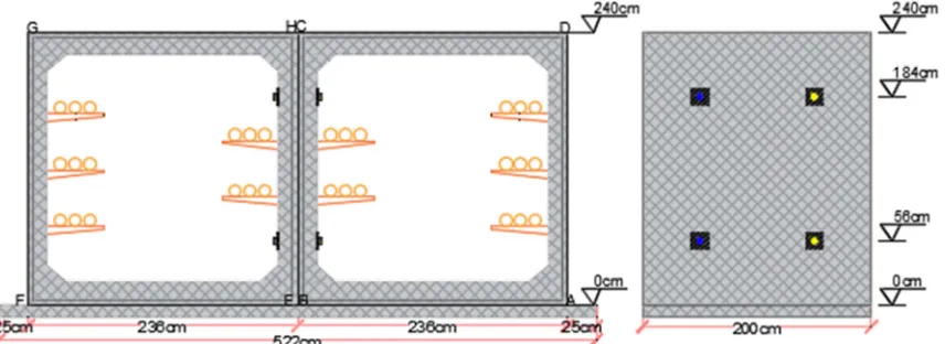
Figure 1. Typical adjacent box culvert and its corner numbering.
2. Materials and Methods
In order to study the behavior of all the possible standard adjacent box culverts three dimensional finite element model were prepared for the standard size of adjacent longitudinal box culvert as per GB50010. [14] This study includes the model of three dimensional solid elements soil (C3D8) and three dimensional solid elements for concrete (C3D8) having geometric and material linearity. The soil was loaded and model based on two loading area which is 1m*1.5m and 1m*2m. The settlement was studied for all the load steps of double box tested using brick element including flexible and ridged connection concerning to soil beneath, side soil, both box culvert and floor reaction. [15, 16]
2.1. Material Properties
Methods comparing with each other, the finite element software ABAQUS was used to model and analyze. The vertical
Table 1. Material property of the modeling.
Item No. Size(m) Unit type Modulus of elasticity(MPa) Poisson’s Ratio Density (Kg/m3)
Soil 30x30x30 C3D8 4E7 0.3 2000
Box culvert 2X2 C3D8 3.25E10 0.3 2400
Floor Reaction 30X5.22 C3D8 3.25E10 0.3 2400
2.2. Mesh Generation
Because of the symmetry of the combined adjacent culvert section, the geometry was considered in the mesh generation, and it was regarded as a three dimensional solid elements for soil beneath, side soil, both box culvert and floor reaction. The models were tested for confirming the geometry dimension and the mesh density, and the final model given vertical displacement (settlement) using corner point identification. All of the elements are standard (C3D8)-8 node linear brick meshed separately. The mesh element generated high on the part soil and least on the part floor reaction. In addition to this, the mesh node generated high on the part box culvert and least on the part floor reaction. Thus, the total mesh generates 191,130 elements and 35,855 nodes. [17]
2.3. Contact Modeling
The adjacent box culverts to the connection form and the boundary condition are connected by screw bolts. The screw bolt constraint is equivalent to the binding contact (tie constraint) sections of the two culverts, that is, the binding contact between left and right inner surface of the box culvert using surface to surface contact elements considered as the left box culvert as master surface but the right box culvert as slave surface. In
addition to this, the friction contact between the box culvert and the soil of the lower box is the same as the binding contact between the box culvert and the soil. It is considered that the box culvert will contact surface to surface element on the upper surface of floor reaction and side soil when the connection concern to flexible and ridged. Thus, the bottom surface of floor reaction and bottom surface of side soil surface during the analysis binding contact with beneath soil. There is a compression relationship between the box culvert and the soil on both sides. Therefore, when the box culvert is subjected to settlement and torsion around the long box, the soil will provide a favorable hindrance, i.e. close contact with the side of the box culvert, so the side of the box culvert is bound to the side soil by considering separately master surface and slave surface.
2.4. Load Applications
In order to correspond to the step by step loading of the test process, loads are located on the right side culvert soil on a 1m*1.5m and 1m*2m areas. The vertical displacement (settlement) of the lower right corner of the right culvert is controlled loaded. The vertical displacement of the lower right corner is approximately satisfied by ABAQUS software calculation. The load of various parts of soil is shown in Table 2.
Table 2. The load of various parts of soil.
Event No soil on both side Free soil on both side Soil on both side Free soil on both side
Load(N/m) 7E7 6.2E7 1E8 1E8
3. Results and Discussions
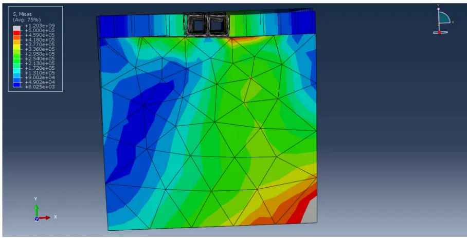
The output database files in ABAQUS were read by visualization module to create contour plots, animations, XY plots, and tabular output of the results. Crack is not supported by visualization mode so it is read in data file, which identifies the cracked elements and the level of stress at that point. [18-20]
According to the results of software calculation, the deformed and un-deformed form of the adjacent box culvert is obtained, as shown in Figure 2 and Figure 3. The corners are numbered respectively, as shown in Figure 1. The vertical displacement (settlement) of each corner point is calculated by the ABAQUS software. The vertical displacement (settlement) is positive downward.
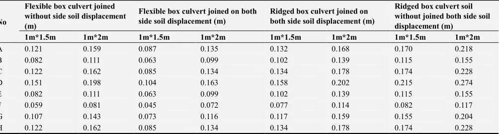
Table 3. The vertical displacement of adjacent box culvert.
No
Flexible box culvert joined without side soil displacement (m)
Flexible box culvert joined on both side soil displacement (m)
Ridged box culvert joined on both side soil displacement (m)
Ridged box culvert soil without joined both side soil displacement (m)
1m*1.5m 1m*2m 1m*1.5m 1m*2m 1m*1.5m 1m*2m 1m*1.5m 1m*2m
A 0.121 0.159 0.087 0.135 0.132 0.168 0.170 0.218
B 0.082 0.111 0.063 0.099 0.102 0.139 0.115 0.155
C 0.122 0.162 0.085 0.134 0.134 0.178 0.174 0.228
D 0.151 0.198 0.104 0.163 0.158 0.202 0.215 0.274
E 0.082 0.111 0.063 0.099 0.102 0.139 0.115 0.155
F 0.059 0.081 0.045 0.072 0.077 0.114 0.082 0.117
G 0.107 0.143 0.073 0.116 0.117 0.159 0.155 0.204
Figure 2. Deformed and un-deformed adjacent box culvert with flexible joint.
Figure 3. Deformed and un-deformed adjacent box culvert with rigid joint.
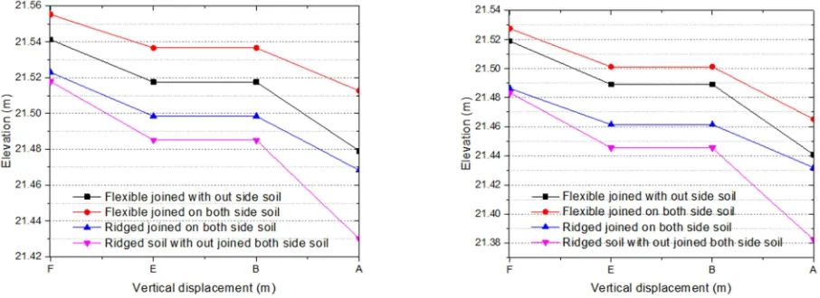
Figure 5. The vertical displacement for lower corner point with 1m*1.5m and 1m*2m.
According to the Table 3, The vertical displacement (settlement)was analysis concerned four modeling system subject to two loading area such as flexible box culvert joined without side soil displacement, flexible box culvert joined on both side soil displacement, ridged box culvert joined on both side soil displacement and ridged box culvert soil without joined both side soil displacement as well as loading area of 1m*1.5m and 1m*2m. So that the upper (roof slab) corner points of the vertical displacement had been appeared minimum settlement predicted at the corner point of G with 0.073m when the adjacent longitudinal box is flexible jointing both side as well as 1m*1.5m loading area and its maximum settlement also predicted at the corner point of D with 0.274m. When the adjacent longitudinal box is ridged without jointing both side as well as 1m*2m loading area. In addition to this, the lower (floor slab) corner points of the vertical displacement had been appeared minimum settlement predicted at the corner point of F with 0.045m when the adjacent longitudinal box is flexible jointed both side as well as 1m*1.5m loading area and its maximum settlement also predicted at the corner point of A with 0.218m. When the adjacent longitudinal box is ridged without jointed both side as well as 1m*2m loading area. Thus, compared with two working conditions of side soil, it is found that the predicted settlement of the left box culverts is less than that of right box culverts. This is because, the settlement of the right lower box soil has little effect on the left side of the culvert when the two culverts are free, and when the two culverts are just joined and coordinated which is given the result that, the left box culvert will be driven to foundation settlement together with right box culvert due to differential settlement under consideration of different loading area and Joints. The vertical displacement of the joint corner points of the HC and EB can also reflect settlement problem. Since the adjacent longitudinal box made from 15 box culverts connected in series. In this case, the torsional stiffness of the adjacent longitudinal box direction is smaller than of the actual production.
4. Conclusions
This study developed the finite element analysis of the
differential settlement prediction for adjacent longitudinal precast box culvert and subject to different loading conditions including different loading area. The main simplified variables included the settlement regarding to connection of the adjacent box culvert concerning to the flexible and ridged connection. Based on interpretations and discussions of the simplified results, the major findings were summarized as follows;
The main factors of the resistance foundation settlement of the box culvert are the clearance of the adjacent longitudinal box culvert joint and the length of the single box culvert. If the adjacent longitudinal box culvert joint can be changed to make it have better deformation ability the box culvert to resist foundation settlement can be improved significantly.
When the soil is under the settlement, the moment between the adjacent box culvert due to gravity and earth pressure acts on the flexible connection, which will produce local compression on the side wall of longitudinal box culvert and also leading to cracks and damage in advance as well as the invasion of water vapor in the soil, and have a negative impact on the performance of the internal utility line.
Acknowledgements
This research was financially supported by the National Key Basic Research Program of China (973 Program CSC No.2016GXZ133) and Heilongjiang Zhongxin LuQiao Material Limited Company.
References
[1] T. Alkhrdaji, and A. Nanni, "Design, Construction, and Field-Testing of an RC Box Culvert Bridge Reinforced with GFRP Bars" Non-Metallic Reinforcement for Concrete Structrues-FRPRCS-5, pp. 1055-1064 2001.
[2] M. O'Rourke and G. Ayala, "Pipeline Damage Due to Wave Propagation," Journal of Geotechnical Engineering, vol. 119, pp. 1490-1498, 1993.
[4] A. Shatnawi, G. Almasabha, and B. Tarawneh, "Structural Behavior of Concrete Box Culverts under Deep Burial,"
Journal of Pipeline Systems Engineering and Practice, vol. 8, p. 04017025, 2017.
[5] J. Y. a. H. Wang, "Seismic Response Analysis of Shallow Utility Tunnel in Liquefiable Soils," ICPTT 2012, 2012.
[6] K. Garg Anil, Abolmaali, A., & Fernandez, R., "Experimental Investigation of Shear Capacity of Precast Reinforced Concrete Box Culverts," Journal of Bridge Engineering, vol. 12, pp. 511-517, 2007.
[7] G. B.-x. XU Ting, "Finite Element Analysis and Drawing of Internal Force on Box Culvert," Journal of disaster prevention and reduction 2018.
[8] M. V. R. R. T. Tejaswini, "Analysis of RCC beams using abaqus," Internationa journal of innovtion in engineering and technology, vol. 5, pp. 248-255, 2015.
[9] A. J. Wang Shuhong, Jie Rula, Wang Pengyu, Liu Weihua, "Simulation of Force Performance of Precast Rectangular Box Culvert and Its Potential Failure Mode," Journal of Northeastern University (Natural Science), pp. 260-265, 2018.
[10] G. Rui, "Research on Key Technology of Super-long Box Culvert Jacking in Expressway Shallow Covering Soil,"
Chang'an University, 2014.
[11] W. Chaoyang, "Practice of the method of grouting to treat uneven settlement of culvert foundation," Shanxi Science and Technology, vol. 26, pp. 94-95, 2011.
[12] L. Feng, "Analysis of differential settlement of bridges and culverts on highways and special construction techniques,"
changsha University of Science and Technology, 2005.
[13] Y. Liang, "Study on Differential Settlement of Widening of Culverts in Large Span of Expressway," Sichuan Building Materials, vol. 44, pp. 165-166., 2018.
[14] C. o. China, "Code for design concrete structures-GB50010,"
Publishing House of building Industry in China, Beijing (in Chineses), 2010.
[15] A. Abolmaali, & Garg, A., "Shear Behavior and Mode of Failure for ASTM C1433 Precast Box Culverts," Journal of Bridge Engineering, vol. 13, pp. 331-338, 2008.
[16] R. I. Pawtucket, "Abaqus/CAE Users Guide," 2014.
[17] X. L. G. C. X. W. a. Y. Liu, "Settlement Prediction and FEM Analysis of Culvert Section under High-Filled Embankment,"
International Pipelines Conference 2008, 2008.
[18] K. Garg Anil, & Abolmaali, A, "Finite-Element Modeling and Analysis of Reinforced Concrete Box Culverts," Journal of Transportation Engineering, vol. 3, pp. 121-128, 2009.
[19] S. Jie, "Large-section pipe shed Numerical simulation of box culvert structure with box culvert jacking," Henan Science,
vol. 03, pp. 457-460, 2007.