Observation of the E
ff
ect of Energetic Ions on Pellet Ablation
in the Large Helical Device
Mitsuyasu HOSHINO, Ryuichi SAKAMOTO
1), Hiroshi YAMADA
1,2), Tokihiko TOKUZAWA
1),
Kazumichi NARIHARA
1), Masaki OSAKABE
1), Hisayoshi FUNABA
1), Ryuhei KUMAZAWA
1),
Tetsuo WATARI
1)and the LHD Experimental Group
1)Department of Energy Engineering and Science, Nagoya University, Nagoya 464-8603, Japan 1)National Institute for Fusion Science, Toki 509-5292, Japan
2)The Graduate University for Advanced Studies, SOKENDAI, Hayama 240-0193, Japan
(Received 10 January 2006/Accepted 24 April 2006)
Ablation of a solid hydrogen pellet in hot plasmas was investigated in the Large Helical Device (LHD). The penetration depth of the injected pellets in the experiment was compared to a theoretical model employing abla-tion due to the heat flux of fast ions as well as thermal electrons. Shallower penetraabla-tion than that predicted based on the model considering only electrons was observed in LHD plasmas in the presence of highly energetic (up to 180 keV) fast ions due to neutral beam injection (NBI). This discrepancy can be quantified by the contribution of fast ions in terms of the stored energy of fast ions. The ablation model calculation taking into consideration the effect of thermal electrons and fast ions agrees with the experimental results obtained by LHD. Scaling which includes the fast-ion effect on penetration depth in LHD was compared with the wider multi-experiment database (IPADBASE) [L.R. Bayloret al., Nucl. Fusion37, 445 (1997)].
c
2006 The Japan Society of Plasma Science and Nuclear Fusion Research
Keywords: fueling, ablation of solid hydrogen, neutral gas shielding model, fast ions, LHD, IPADBASE DOI: 10.1585/pfr.1.033
1. Introduction
The establishment of an efficient fueling scenario is a principal issue in the implementation of a future magnetic fusion reactor. Degradation of fueling efficiency results in excess neural gas, which causes enhanced charge exchange loss and consequent sputtering, as well as confinement de-terioration. This loss of fueling efficiency also requires a large pumping capability and increases the tritium inven-tory. To date, gas puffing has been successfully used as a fundamental fueling tool. However, in larger devices there is a concern regarding the worsening of the fueling effi -ciency of gas puffing because most fueled gas is ionized in a hot and thick scrape-offlayer before it penetrates the con-finement region. Therefore, the feasibility and inevitability of gas puffing in a fusion reactor is not necessarily assured. The injection of cryogenic solid pellets, which is an alternative approach to fueling, has been attracting inter-est because of its advantage of deeper and more efficient fueling than gas puffing (see Review Paper [1]). Many ex-periments support the promise of pellet injection due to its direct fueling into the plasma core region beyond the scrap-offlayer of a fusion reactor. Accumulated experi-mental observations have shown that the fueling efficiency of pellet injection improves with penetration depth [2–4]. Here it should be pointed out that the penetration depth of pellets involves two stages of dynamics. The first stage is
author’s e-mail: [email protected]
the penetration of solid pellets into hot plasmas. Pellets ab-late due to heat flux from the plasma and leave their mass along their trajectory. The second stage is the prompt drift of ablated high density plasmoid, which is supposed to link with a gradient of the magnetic field and gives a substan-tial mass deposition [5–7]. Therefore, for the prediction of fueling performance it is necessary to clarify the physical mechanisms in these two stages, i.e., the ablation process of pellets and the subsequent drift motion of the ablated plasmoid.
Since the aforementioned processes can be considered separately, the penetration depth determined by the abla-tion process is a primary issue in fueling. This allows the discussion of drift motion as a secondary problem. With respect to the ablation process, the neutral gas shielding (NGS) model [8, 9], which estimates heat flux due to ther-mal electrons and evaluates the shielding effect of ablated neutral gas against it, has been widely accepted as a stan-dard model for explaining the results of tokamak experi-ments. A study of the international pellet ablation database (IPADBASE) has indicated that the penetration depths in the different devices follows regression scaling whose ex-pression is similar to NGS scaling under the condition of scatter in the scaling data of ohmic, NBI, and ICRH plas-mas [10]. An effect of fast ions on the ablation can be a potential cause of this scattering.
In contrast to electrons, the effect of energetic ions on
c
Plasma and Fusion Research: Regular Articles Volume 1, 033 (2006) ablation is supposed to be much less significant because of
the larger shielding effect of the ablated cloud. Although a variety of models which account for the effects of en-ergetic ions has been proposed, experimental studies on those effects, at least systematic studies, have not yet been reported and the validity of the proposed model has not been confirmed. This is due to the lack of availability of an experimental condition which contains a large amount of energetic ions. Recently, a sophisticated ablation model that describes the interaction of a pellet with energetic ions and electrons in ICRH and LHCD experiments has been re-ported [11]. However, the current experimental documen-tation of the effect of fast ions is insufficient.
In D-T fusion reactor conditions, alpha particles with an energy of 3.5 MeV account for several percent of all ions in burning plasmas. Therefore, verification of the ablation model including the effect of energetic ions is a prerequisite for predicting the penetration depth in fusion plasmas.
The Large Helical Device (LHD) [12], which is a large-scale heliotron device, employs negative ion-based neutral beam injection (NBI) with an accelerating voltage of 180 keV (the proton ratio is 100 % since the NBI em-ploys a negative ion source) [13]. This is in contrast to the fact that major tokamaks utilize NBI with an energy of at most 100 keV. Since pellet injection is routinely available in LHD [14, 15], an experimental study of the penetration depth of pellets in NBI heated plasmas in LHD can make a unique contribution to our understanding of the pellet ab-lation mechanism, in particular the effect of energetic ions over a wide energy range. In this article, we describe ex-perimental observations of pellet penetration depth, reflect-ing information regardreflect-ing pellet ablation in plasmas which are rich in energetic ions. We compare these observations with the results of a theoretical model. Based on avail-able understanding derived from experimental study using LHD, tokamak data described in the IPADBASE are re-considered with emphasis on the effect of energetic ions.
2. Ablation Model
2.1
The NGS ablation model
The neutral gas shielding (NGS) model [8, 9] is a sim-ple theoretical model describing pellet ablation in high temperature plasmas. A neutral shielding cloud around the pellet is formed by the incident energy flux from a background plasma and assumes a steady state and shock-free transonic flow which is continuously accelerated to supersonic flow. The 1-D spherically symmetric hydro-dynamic model of the expansion in the ablation cloud is then solved in the model. Only the thermal electron as mono-energetic incident particles is regarded in pellet ablation since plasma electrons dominate the cloud heat-ing and ionization, consequently the ablation of the pel-let in the model [1]. By assuming the continuous loss of mono-energetic electrons in the ablation cloud, the
energy-dependent loss functionL(E), which is a semi-empirical formula [16], is defined as dE/dr = ρcloudL(E)/m, where mandρcloud are the average molecular mass and the mass density of the cloud, respectively. In this model, the re-cession speed of the pellet surface is given by the form of simple scaling laws [9]
drpel/dt∝r−pel2/3n1/3e∞Te1.64∞ , (1) whererpel,ne∞, andTe∞are the equivalent spherical pellet radius, the background electron density, and temperature, respectively.
2.2
Impact of energetic ions on pellet
abla-tion
Only the thermal effect of electrons on pellet ablation is considered in the original NGS ablation model [8, 9]. However, the extra-thermal effect (involving fast ions and energetic electrons, etc.) should be taken into account in order to understand pellet ablation in terms of the inter-action with energetic particles in a hot plasma. In Refs. [17–19], the effect of fast ions on ablation has been well studied both experimentally and theoretically. The effect of thermal ions and alpha particles on pellet ablation must also be quantified for a future fusion reactor. In this sec-tion, the contribution of energetic ions to pellet ablation is estimated while that of thermal electrons is still predomi-nant.
In the theoretical ablation models, the rate of the con-tribution of energetic particles to pellet ablation is esti-mated using a simple formula [17, 19, 20]. The heat source in the cloud due to thermal electrons and fast particles W = (fB/m)qΛ[eV·kg−1·s−1] can be an effective indi-cator, where fBis the fraction of the heat flux due to elec-trons and fast ions. It is assumed that these fractions are uniform in the cloud, fBe≈0.6 on electrons and fBf ≈1.0 on fast ions, where they are determined by the effects of both the atomic processes and that of the geometry of the flux incidence. As well,m,q[eV·m−2·s−1], andΛ[m2] are the average molecular mass, the heat flux to the pellet, and the effective cross-section for heat flux loss in the shield-ing cloud, respectively. For the heat fluxq, the distribution function of incident thermal electrons and ions assumes a Maxwellian (n,TandE=2Tare density, temperature and energy, respectively) and those of fast particles are given by using a Fokker-Planck code as follows:
qe,i∞=12
e πme,i
ne,i∞Ee3/2,i∞, (2)
qf,α∞= πmf,α
2e
∞
0
v5f(v)dv, (3)
f(v)=
Sτslowdown
4π(v3+v3c) forv > v(t) 0 forv < v(t),
(4)
whereme,i,mf,α,S [m−3·s−1],τ
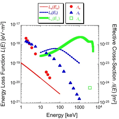
Fig. 1 Energy loss functionL(E) and the effective cross-section Λ(E) of electrons, fast ions, and alphas.
lower velocity limit for the distribution function, respec-tively. The effective cross-section is written byΛ=σˆT+ 3L(E)/2E, where ˆσTis the total cross-section for the elas-tic backscattering of electrons [9] andL(E) [eV·m2] is the energy loss function of the incident particles in the cloud, which is the fitted formula given by a semi-empirical cross-section for the discrete excitation, ionization, and dissocia-tion processes. The energy loss funcdissocia-tionL(E) for electrons [16], fast ions [21], and alpha particles [20] has a different energy range and energy-dependent function as shown in Fig. 1.
The ratio of the heat source in the cloud resulting from energetic particles against that from thermal elec-trons,ηf,α,i≡Wf,α,i/We, shows an effective contribution of energetic particles to pellet ablation since the heat source of the cloudW is directly related to the ablation rate as ˙
rpel∝(We∗+Wf∗)1/3in the ablation model [19, 20], where the asterisk indicates the value at the sonic radius. In what follows, we assumeTe = Tiand the thermal energy E=2T.
The definitional equationηf,iis estimated by using the value atρ = 0.6 of 1) the assumed electron density pro-files (constantneprofiles withne0=1.0,2.0,3.0,4.0,5.0× 1019m−3), 2) the corresponding linear electron temper-ature profiles predicted by 1.5 times the ISS95 scaling [22], and 3) the density profiles of fast ions calculated by the FIT code [23] in LHD plasmas (at the NBI de-position power 10 MW). Under the present experimental conditions, LHD is a unique device that can experimen-tally demonstrate pellet ablation by fast ions since ener-getic NBI heating may affect the pellet ablation rate. The value ofηαis estimated by the value atρ=0.6 of the corre-sponding profiles under the condition of the fusion energy gain Q = 5 (Te0 = 33 keV, ne0 = 1.0×10²⁰m−3) and Q=10 (Te0 =23 keV,ne0 =3.5×10¹⁹m−3) in the
Inter-Fig. 2 Ratio of the effective contribution of energetic particles to pellet ablation against thermal electronsηf,α,iversus their
energy atρ=0.6 of the corresponding profiles.
national Thermonuclear Experimental Reactor (ITER) [24] and two cases (Te0 = 22 keV,ne0 = 2.0×10²⁰m−3 and Te0=27 keV,ne0=2.8×10²⁰m−3) in the Force Free Heli-cal Reactor (FFHR) [25], whileηiis also determined by the parameters of ITER. The value ofηf,α,i is a local param-eter in target plasmas and the value atρ =0.6 is selected because it can be a representative parameter for ablation in both shallow and deep penetrations. Figure 2 shows the ratio of the effective contribution of energetic particles to the pellet ablation against thermal electronsηf,α,iversus the energy of fast ions, alpha particles (3.5 MeV), and thermal ions.
Plasma and Fusion Research: Regular Articles Volume 1, 033 (2006) is not necessarily lost even in fusion plasmas due to needs
for current drive and auxiliary heating leading to ignition. Accordingly, the effect of energetic ions on ablation must be assessed.
We have used the ABLATE code [19] to evaluate the effect of fast ions on pellet ablation. This code can deal with not only thermal electrons but also fast ions produced by NBI heating in regard to their role in ablation. It can also calculate the ablation rate profile (i.e., the pellet pen-etration depth) including the effect of non-time or time-dependent profiles of electron temperature and density dur-ing pellet ablation. The model is essentially extended from the NGS model [9] by the addition of the effect of fast ions. The attenuation of the energy of fast ions is newly expressed by the energy loss function of incident fast ions in the cloudLf(Ef) [21], while the solution of the Fokker-Planck equation for fast ions is used to calculate the energy and the heat flux of fast ions as seen in Eq. (4). The valid-ity of this fast ion model was first demonstrated on the new region of the beam energy since NBI heated plasmas con-tain fast ions up to 180 keV in LHD. The analysis of pellet penetration depth using this code is discussed in Sec. 4.
3. Experimental Setup
The Large Helical Device (LHD) has a heliotron con-figuration which is composed ofl=2/m=10 supercon-ducting helical coils and three pairs of poloidal coils, and is superior to high density and steady state operations [12]. Its basic specifications include a nominal major radius of 3.9 m, an average minor radius of about 0.6 m, a plasma volume of 30 m3, and a maximum magnetic field strength of∼3 T. Plasma heating is performed by three tangential neutral beam injection (NBI) systems all using a negative ion source [13]. The beam energy is 120 to 180 keV and the available total heating power is up to 13 MW. The electron temperature and density are measured by means of Thomson scattering [26] and an FIR interferometer [27], respectively.
Two pellet injectors (an in-situ pipe-gun pellet injec-tor and a repetitive pellet injecinjec-tor) are installed in LHD. On the pipe-gun pellet injector, solid hydrogen pellets are pro-duced in 8 barrels, and the pellet velocity and size are 1,000 to 1,200 m/s, with each cylinder being 3.0 mm in diameter and 3.0 mm in length (∼1×10²¹atoms) [14]. On the repet-itive pellet injector, pellets are continuously formed and injected at a maximum repetition frequency of 11 Hz, and the pellet velocity and size are 300 to 700 m/s, with each cylinder being 2.5 mm in diameter and 2.5 mm in length (∼6×10²⁰atoms) [15]. From both injectors, pellets are in-jected through the outer port of LHD into the plasmas by means of the pneumatic pipe-gun method using high pres-sure He gas. The pellet velocity is meapres-sured by the time-of-flight (TOF) which is a system that determines velocity based on the time difference of the pellet intersecting two pairs of laser-diodes and photodiodes about 1.8 m apart.
The pellet mass is measured by the microwave cavity of the TE103 mode [28] on the pipe-gun pellet injector. We conclude that the measurement deviation of the pellet ve-locity and mass are 0.3 - 1.4 % and∼5 %, respectively.
The measured penetration depth is determined based on the duration of Hαemissions measured from the back-side of the pellet path and the assumption of a constant pellet velocity which is measured by TOF prior to the pel-let injection into the plasmas. It has been previously con-firmed that the pellet velocity during ablation in a plasma maintains its initial injection velocity; in other words, the radial pellet velocity is the same but the pellet velocity in the direction of the magnetic field line is accelerated by heating the pellet [29]. The duration of Hα emission, i.e., approximately the pellet lifetime, cannot be arbitrar-ily determined since the ergodic region is complex and the temperature and density in this area of LHD is unknown. Therefore, the start of pellet ablation is estimated based on the assumptions that the pellet ablates from the last closed flux surface of the vacuum magnetic configuration and that the pellet velocity is constant during the ablation, while the end of pellet ablation is determined by a sharp fall of the Hα signal. Ambiguity in penetration depth due to these assumptions is 0.5 - 7.5 cm including the measure-ment deviation of the pellet velocity and the scattering an-gle of pellet travel in the plasmas, while the plasma radius is about 0.85 to 0.98 m. Both the NBI heating condition and electron density before pellet injection are surveyed in the experiment, and neither ECH nor ICRH are used dur-ing the phase of pellet injection to document the effect of fast ions by NBI heating. In addition, pellets that pene-trate beyond the magnetic axis are excluded (i.e., pellets of the penetration depth normalized by the minor radius > 1 are not considered) since electron temperature and den-sity profiles change significantly when a pellet passes the plasma center.
4. Experimental Results
The results of a total of 52 discharges (129 datasets) in the pellet-fueled LHD experiments are included in order to analyze pellet penetration depth. The ranges of the LHD dataset are Te0 = 0.76 - 3.43 keV, ne0 = 0.06 - 0.60×10²⁰m−3, m
pel = 3.00 - 7.04 ×10²⁰atoms, vpel = 212.89 - 1169.60 m/s, Pdep = 0.53 - 9.62 MW, andENBI = 104.94 - 174.64 keV. The data include NBI Co-(12 %), Counter-(10 %), and Balance-(78 %) injection. The deposition power is 0.2 - 4.2 MW. Regression anal-ysis is applied by the parameters of the NGS scalingTe0, ne0,mpel, andvpelto investigate trend expressed in the LHD data. The regression expression for the penetration depth is the following formula (see Fig. 3 where RMSE=0.029):
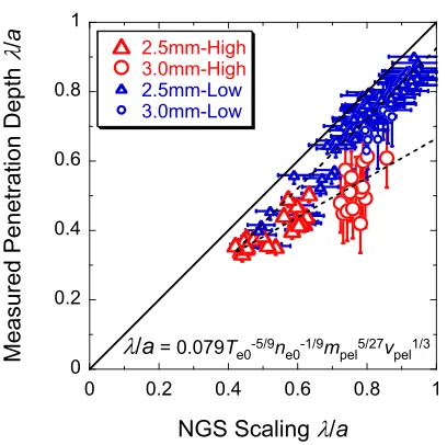
λ/a=0.212Te0−0.685±0.027n−e00.039±0.020
Fig. 3 The new scaling using the parameters of NGS scaling (Te0,ne0, mpel, andvpel) compared to the measured
pel-let penetration depth in LHD.
Fig. 4 The relationship between the measured pellet penetration λ/aand the stored energy of fast ionsWf0in pellet-fueled
LHD discharges.
plasma radius, λ/a = 1, indicates that the pellet has reached the plasma center. Measured penetration depth is well expressed by Eq. (5). However, the standard error of the mean of the electron densityne0is not effective since the electron densityne0is strongly correlated with the elec-tron temperatureTe0and the deposition powerPdepin the present data. Therefore, a new parameter is needed to de-scribe the effect of fast ions in LHD plasmas.
The stored energy of fast ions in the plasma center is introduced as an indicator of the effect of fast ions on ablation,
Wf0=Pdep×τslowdown,0, (6) where Pdep is the NBI deposition power in LHD plas-mas andτslowdown,0 ∝ (Te03/2/ne0) ln(1+(E/Ecr)3/2) is the
Fig. 5 NGS scaling considering only the effect of thermal elec-trons on the ablation compared to the measured pel-let penetration depth at the same magnetic configuration (Rax=3.6 - 3.7 m,Bt≥2 T).
slowing-down time at the plasma center. Figure 4 shows the distribution of data on the plane of the measured pellet penetration and the stored energy of fast ions in the pellet-fueled LHD discharges. The circle represents the 3-mm diameter pellet with fast pellet velocity on the pipe-gun pellet injector and the triangle is the 2.5-mm diameter pel-let with slow pelpel-let velocity on the repetitive pelpel-let injector, as described in the previous section. The penetration depth becomes shallower with the increase of the energy of fast ions, and one can say thatλ/acorrelates withWf0. How-ever, it should be noted that colinearity betweenWf0 and Te0cannot be sufficiently excluded in the present database. The two curves composed of circles and triangles show the difference of the penetration depth due to the different pel-let velocity and mass depending on the two injectors.
Plasma and Fusion Research: Regular Articles Volume 1, 033 (2006)
Fig. 6 New scaling using the stored energy of fast ionsWf0
in-stead of the electron densityne0 compared to the
mea-sured pellet penetration depth in LHD.
the difference between measured and predicted pellet pen-etration is large for deep penpen-etration although for shallow penetration there is no difference between the measured and predicted results in the two cases. The discrepancy of experimental results from NGS model suggests the effect of fast ions on pellet ablation since NGS scaling considers only thermal electrons. This tendency is pronounced when the pellet penetrates deeply andWf0is high. It is concluded that the experimental data produced from LHD cannot be expressed by NGS scaling alone.
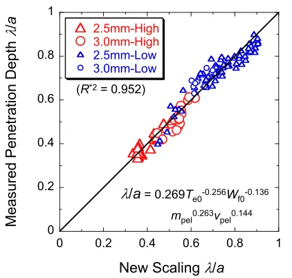
In order to derive an empirical expression of the pene-tration depth, regression analysis was applied. The energy of fast ionsWf0is used as a parameter in the statistical anal-ysis since it has a potential to express the effect of fast ions on pellet ablation. The obtained regression expression is the following formula:
λ/a=0.269Te0−0.256±0.069Wf0−0.136±0.024
×m0pel.263±0.047v0pel.144±0.030. (7) As shown in Fig. 6 (RMSE = 0.026), the regression ex-pression for the penetration depth accounts for the mea-sured pellet penetration. The energy of fast ions Wf0 as a parameter is requisite to predict the measured penetra-tion depth since the estimate value (i.e., the error bar of the multiplier factor) is smaller when the electron densityne0 instead ofWf0is used.
As described in Sec. 2, the new ABLATE code [19] is employed to analyze the pellet penetration depth in the LHD experiments. For this calculation, the fitting elec-tron temperature and density profile based on experimental measurements using the Thomson scattering and the FIR interferometer, and the density profile of fast ions calcu-lated by the FIT code [23] are used. The ABLATE code considering not only thermal electrons’ but also fast ions’ contribution to the ablation can calculate the ablation rate
Fig. 7 Hαprofile compared to the calculated ablation rate profile in the case of highWf0(mpel=5.30×10²⁰atoms,vpel =
1129.70 m/s, andWf0=42.12 kJ).
Fig. 8 Hαprofile compared to the calculated ablation rate profile in the case of lowWf0(mpel =6.19×10²⁰atoms,vpel =
1148.40 m/s, andWf0=16.14 kJ).
un-Fig. 9 ABLATE penetration depth considering only the ablation of thermal electrons compared to the measured penetra-tion depth.
Fig. 10 ABLATE penetration depth considering the ablation of thermal electrons and fast ions compared to the measured penetration depth.
derestimates the penetration depth, which is pronounced in the case of high Wf0. Although the scattering is not reduced in the comparison with ABLATE, the correspon-dence between the experimental observation and the model calculation is improved. As well, deviation between the subsets (the high case ofWf0/Wdia>5 % and the low case ofWf0/Wdia <5 %) is reduced. Penetration depths of the model including the effect of fast ions account for the ex-perimental data.
5. Discussion
The IPADBASE [10] has been assembled to enable studies of pellet ablation theories that are used to describe the physics of pellet ablation in a tokamak plasma (JET,
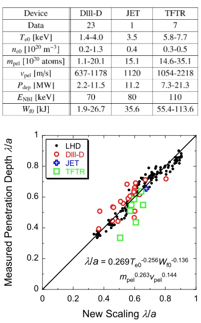
Table 1 Plasma and pellet parameters in Dlll-D, JET, and TFTR.
Fig. 11 New scaling compared to the measured pellet penetration depth on the combined pellet dataset (DIII-D, JET, and TFTR).
Tore Supra, DIII-D, FTU, TFTR, ASDEX Upgrade, JIPP T-IIU, RTP, and T-10). Data regarding NBI heated plasmas are selected as shown in Table 1. The data regarding TFTR have 5 - 10 times and two-times the pellet mass and veloc-ity, respectively, than does LHD, and the data are identi-fied as a case of highWf0 as in the data of LHD because of energetic NBI heated plasmas (ENBI ∼ 110 keV). The data regarding Dlll-D and JET are very similar to LHD data except for the pellet mass and the NBI injection en-ergy. These data are compared with the regression expres-sion of the penetration depth expressed in Eq. (7) regard-ing LHD as shown in Fig. 11. Dlll-D and JET data agree closely with the scaling, but the dataset from TFTR shows a trend different from that of LHD. The shapes ofTeand neprofiles in the IPADBASE are linear/hollow for Dlll-D, parabolic/parabolic for JET, and peaked/peaked for TFTR, respectively. In LHD experiments, these profiles are typi-cally linear/flat or hollow, so the profile significantly varies among devices. Therefore, the scaling of the penetration depth might be improved by considering the dependence of these profiles.
Plasma and Fusion Research: Regular Articles Volume 1, 033 (2006) in Fig. 10. However, the shape and peak position of the
pellet ablation rate profile differ from that of the measured Hα profile in Figs. 7 and 8. This distinction is especially significant in the case of lowWf0; consequently, the issue should be solved by the validation of Hα intensity based on the experimental observations of the ablation cloud and plasmoid. Thus, the model truly representing the experi-mental condition, i.e., the model that takes into considera-tion not only the neutral shielding cloud but also the plas-moid measured by LHD experiments [29], is required for comparison with the Hαradial profile under the same con-ditions. The other problem is a systematic underestimation of the penetration of the 2.5 mm pellets (represented in the figure by triangles). This might be improved by consider-ing the shieldconsider-ing of the plasmoid treated in the neutral gas and plasma shielding (NGPS) model [30], which will take place in a future study.
6. Conclusion
Modeling of the penetration depth of the fueling pel-let is prerequisite for establishing the optimal operational scenario of a fusion reactor. Penetration depth is closely related to fueling efficiency as well as to the impact on the parameters of the bulk plasma. Since the alpha particles play an essential role in heating the plasma in a fusion re-actor, their effect on the ablation process of the injected pellet should be quantified. The present study has provided simulated experimental data describing this condition.
Pellet ablation in terms of pellet penetration depth has been studied under the condition of the presence of the fast ions produced by energetic NBI heating in LHD. We have introduced the stored energy of fast ions,Wf0, con-sidering the effect of fast ions on pellet penetration depth. WhenWf0exceeds several percent of the total energy of the plasma as measured by diamagnetic diagnostics, the pellet penetration depth deviates significantly from the predicted value of the NGS model which treats only the ablation due to electrons. The dependence onWf0 describes the effect of fast ions on ablation in LHD. When this expression is applied to the wider database (IPADBASE), a close agree-ment is found for Dlll-D, whose plasma profile is similar to that of LHD. It is also verified in NBI heated plasmas in LHD that the ablation model including the effect of fast ions on ablation, the ABLATE code, can predict the ob-served penetration depth.
Acknowledgements
The authors would like to thank the LHD technical
stafffor their encouragement and support. Dr. L.R. Baylor kindly made the data regarding IPADBASE available to the authors. We would also like to thank Dr. Y. Nakamura for his thoughtful suggestions on the revision of the ABLATE code and Dr. S. Murakami for his advise regarding the FIT code.
This work is supported by NIFS under Contract Nos. NIFS05ULPP521 and ULPP522.
[1] S.L. Milora, W.A. Houlberget al., Nucl. Fusion35, 657 (1995).
[2] D.K. Owenset al., Pellet Injection and Toroidal Confine-ment(Proc. Tech. Comm. Mtg, Gut Ising, 1988), IAEA-TECDOC-534, IAEA, Vienna 191 (1989).
[3] G.L. Schmidt et al., 1992 International Conference on Plasma Physics(Proc. Conf. Innsbruck, 1992), Vol. 16C, Part I, European Physical Society, Geneva 255 (1992). [4] P.T. Langet al., Nucl. Fusion36, 1531 (1996). [5] R.D. Durstet al., Nucl. Fusion30, 3 (1990). [6] L.L. Lengyel, Nucl. Fusion17, 805 (1977). [7] P.T. Langet al., Phys. Rev. Lett.79, 1487 (1997). [8] S.L. Milora and C.A. Foster, IEEE Trans. Plasma Sci.PS-6,
578 (1978).
[9] P.B. Parks and R.J. Turnbull, Phys. Fluids21, 1735 (1978). [10] L.R. Bayloret al., Nucl. Fusion37, 445 (1997).
[11] B. P´egouri´e et al., Plasma Phys. Control. Fusion47, 17 (2005).
[12] O. Motojimaet al.,IAEA Nucl. Fusion and Plasma Phys. 2004(Vilamoura), paper OV/1-4.
[13] O. Kanekoet al., Nucl. Fusion43, 692 (2003). [14] H. Yamadaet al., Fusion Eng. Des.49-50, 915 (2000). [15] H. Yamadaet al., Fusion Eng. Des.69, 11 (2003). [16] W.T. Mileset al., J. Appl. Phys.43, 678 (1972).
[17] S.L. Milora, Oak Ridge National Lab. Rep. ORNL/ TM-8616 (1983).
[18] S. Sengokuet al.,Plasma Phys. and Control. Nucl. Fusion Res.(Proc. 10th Int. Conf. London, 1984), Vol. 1, IAEA, Vienna, 405 (1985).
[19] Y. Nakamuraet al., Nucl. Fusion26, 907 (1986). [20] S.K. Ho and J. Perkins, Fusion Technol.14, 1314 (1988). [21] H.H. Andersen and J.F. Ziegler,Hydrogen Stopping Powers
and Ranges in All Elements(Pergamon Press, 1977). [22] U. Strothet al., Nucl. Fusion36, 1063 (1996). [23] S. Murakamiet al., Fusion Eng. Des.26, 209 (1995). [24] ITER Physics Basis Editorset al., Nucl. Fusion39, 2137
(1999).
[25] A. Sagaraet al., Fusion Eng. Des.49-50, 661 (2000). [26] I. Yamada and K. Narihara, J. Plasma Fusion Res.76, 863
(2000).